7. Electronics design
This week, we’re making ‘hello world’ boards!
How I started making my design
First, I did a couple things in Adobe Illustrator. Just added some text and labeled some of the components. To me, it made life a lot easier, especially since I don’t know a lot of the shorthand yet. I’ll try to come back to this later and make a list of the electronics shorthand I learned while doing all of my electronics projects.
Next, I started up Eagle. Now the thing with Eagle is that it’s apart of the Autodesk clan. Autodesk bought CadSoft, the makers of Eagle, in 2016. Well, they didn’t exactly get to reprogramming Eagle right away, so my dad had the old version of Eagle on his computer and I had never really gotten to updating it till now. After having the program crash on me so many times, I just had to update it. My dad really didn’t know the new version of Eagle, nor did I, so we were kind of in the dark on how it would look afterwards. Once we started up the program, we found that the interface was easier to use and pretty much had the same tools in the same spot. It’s crazy what Autodesk can do to an already good program. They just go above and beyond.
Actually designing
Now all that stuff above was prep. The next part is starting the schematics. The easiest thing to do to start your schematics is to get all your components laid out first. Now to get the correct library for your components, you need ot download them off the Fabacademy page. I already had my components on my library since my dad had them there before, but it’s still useful to know how to get them. It’s a lot like get libraries for arduino. To get your components on your screen, click ‘add part,’ search for the part you need, and click ‘ok’ as many times as you need to get the right amount of parts. For example, if you want two (2) resistors, hit ‘ok’ twice. If you only want one (1) resistor, hit ‘ok’ once, then hit cancel. Simple as that. Now, once you’ve got all the componenets you listed earlier on the handy dandy picture I provided, you can start really making you schematic. Now, I’d say this is absolutely the worst part. Having to slowly and tediously add a bunch of lines connecting everything is just so boring. Luckily, using labels can make it so much easier. Using lines and paths to connect everything can get super messy, but adding labels can make it a piece of cake. First, you’re gonna want to make a small line coming from the pin that you want to label. Then, make another small line form the pin you want to connect to the previous pin. Now, label the line on that first pin something (GND for example), then label the second line on the other pin the same name (just label it GND too). Boom. Now you’ve got a connection and are starting to build a circuit. Now you’re going to want to look carefully at your picture from before, especially since it’s going to look very different compared to the schematic. What this means is that you’re going to get frustrated, especially when you mess up one tiny thing it’s gonna tip you over the edge and might make you feel like giving up. Now, imagine having your software shut down and you loose all your work in the process. Thats why you should get the latest software. Trust me, I cried while putting my schematic together. It’s not fun.
Alright! We’re done with schematics now that you have everything connected together. Now it’s time to switch to laying out your board. This is where we get all the crazy lines moving around. When I brought my ‘hello world’ board to school, a bunch of people were wondering how I was able to make something so small and complex, but to be honest, I didn’t do any of the routing. I used autoroute. Now, I know a lot of people don’t like autoroute, but my dad likes autoroute, so that meant I just had to like autoroute by proxy. So once you switch from the schematic window to your board window by clicking the button right next to the print button (it should have a green bottom with SCH on the top and BRD on the bottom half). This will switch you into a very different looking screen. Here, you have your components all tangled together by a bunch of yellow lines. Those are you connections which will later become your baord. The red rectangles are your pads, aka where you’ll place your components. Now that we have that out of the way start placing your components around in the areas that you want them to be. The places that you want them to be are where they’ll be least tangled. Obviously, for some components, you’re going to want them to be on the edge of the board (your FDRI header for example). Once you got that mess sorted out, place your mouse on ‘tools’ and drag it down to ‘autorouter.’ This will be the easiest and hardest part of designing your board. Once you click on it, you should see a little window. The only thing you are going to want to touch on there is the effort. Turn your effort up to high and let the program do its thing. I understand that some people don’t like using autoroute because it’s not exactly genuine, but when you think about, what in fabrication is genuine? We are making machines to make our lives easier, right? So why shouldn’t we use machines to make making machines easier? It’s just common sense. Now that reading that took up the time of waiting for autoroute to do it’s thing, you might find that there are some blue lines showing up. Those blue lines are up to no good. That means that autoroute couldn’t find a way to properly connect those routes. Now you have to go in and fix it manually. By using the uproot tool, you can remove this blue line and start connecting more red lines together. If you feel like your board is getting messy, don’t worry about it! Sometimes the only way to solve something is add more junk. If you throw in a couple jumpers (O Resistence resistors) in across some connections that cross over another route, you can get rid of the crossing routes.
Once all of your blue lines are gone and your whole board is correctly place, start getting those gerber files! Go to ‘File,’ the drag your mouse down to ‘CAM Processor’ and click ‘Yes.’ You should get a folder full of files. These are your gerber files and are very important. You are gonna to want to use the file copper_top.gbr. This is what will actually mill out your board!
Milling out a board
This is actually the most difficult part of FabAcademy so far, let alone board making. I’ve never had so much
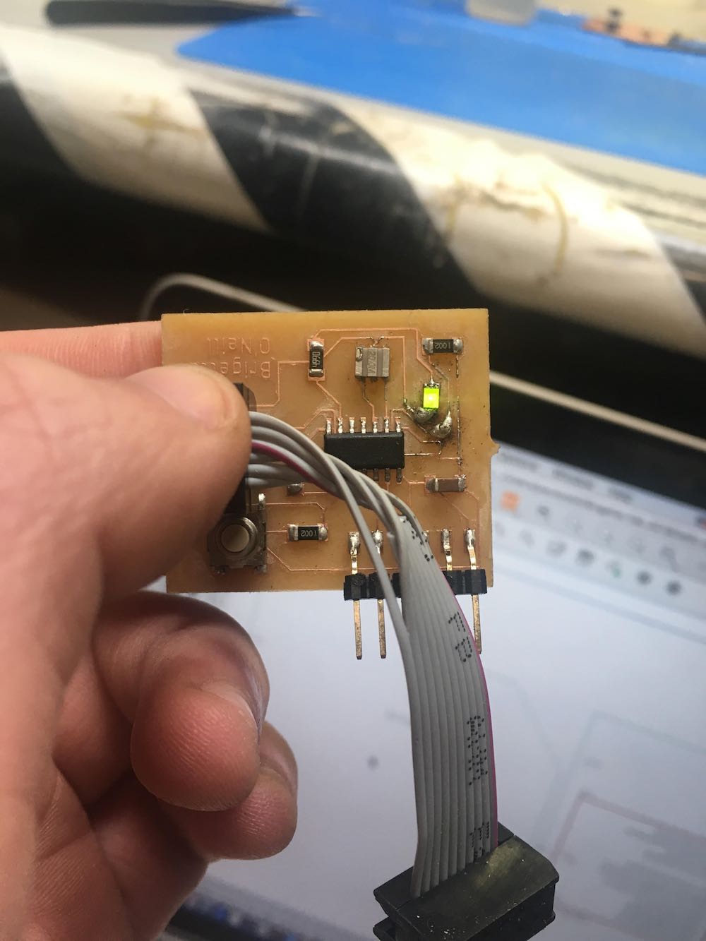
Soldering
Soldering your board can be really tricky. I know I get very angry if something goes wrong when I solder. Some things that will most likely happen to you if you are a novice solderer like me are:
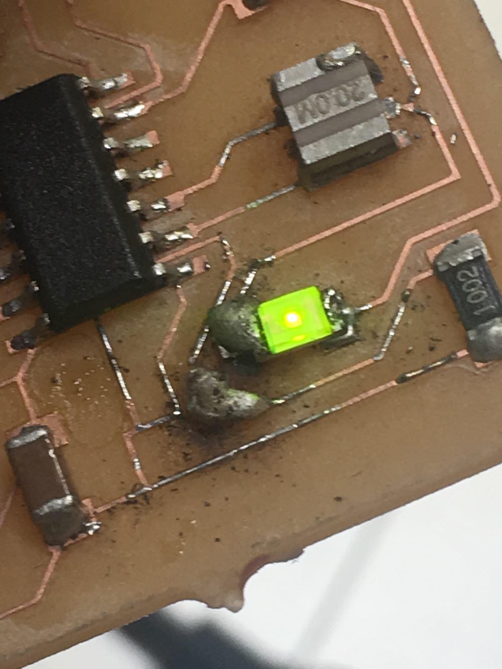
- having to flip LEDS or different components with polarized ends
- pulling up pads
- blobbing too much solder on
- not putting enough solder on
- bridging connections
- having an iron that’s not hot enough
- having some shorts
- frying your board
- frying your resinator
- using rosin or resin flux that makes your board too sticky
Luckily, I got a couple good tricks to help you out with all of these. Sometimes, you can even use these to your advantage!