Week assignments
Group assignment
- Measure the power consumption of an output device
Individual assignments
- Add an output device to a microcontroller board you've designed and program it to do something
Group assignement
You can find documentation about our group assignement on our group page.
The LCD screen with FTDI connection
With my connected chess board, I will have to find a way to give the player an information on what move has been played by the opponent.
At first, I would have liked a system of LED to light the square of the moved piece and the destination square. This could be an improvement for my project. But to be on time with the FabAcademy schedule, I think I am going to use a seven segment display system to indicate what move has been played.
Because I don't have yet a seven segment at the lab, I am doing the exercice with a lcd display.
Electronic design
You can get my KiCAD archive for this week here
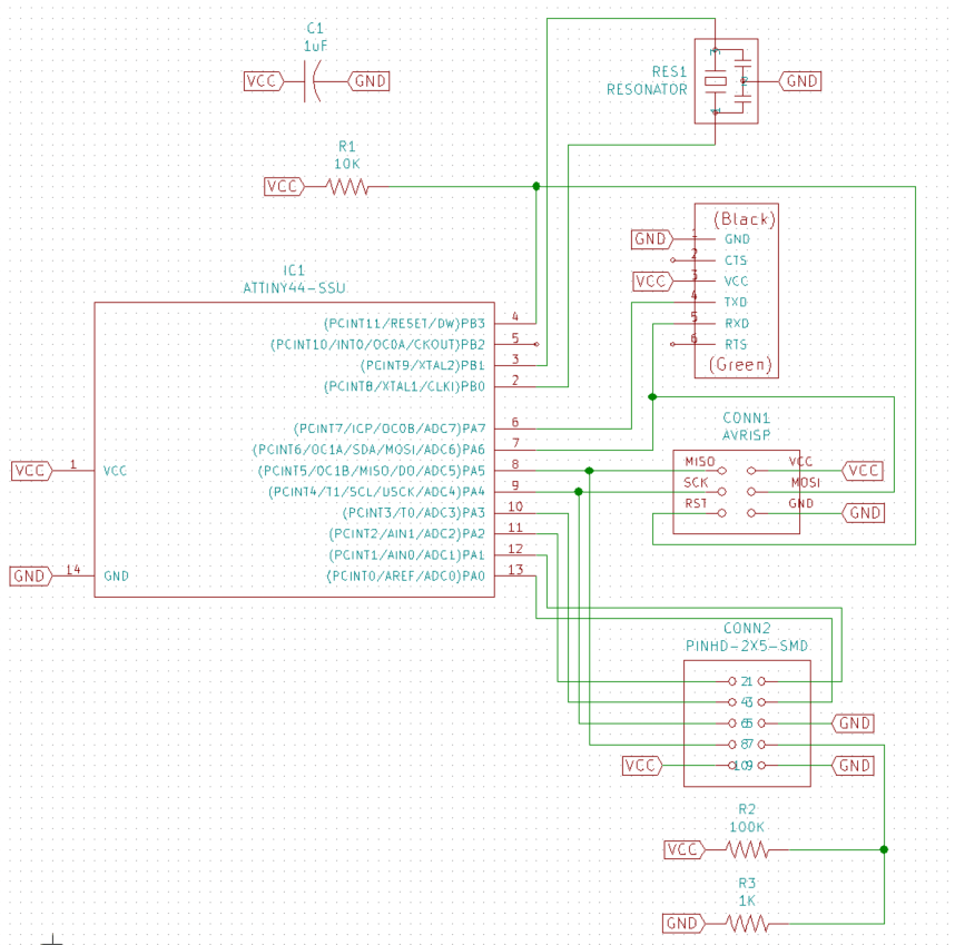
Below is the schematic used for this week. I helped myself with Neil's Design.
Because we were out of 0.4mm end mill we had to use a 0.8mm end mill. This has affected my schematic. The second difference is that I wanted an FTDI cable to send information to the LCD display.
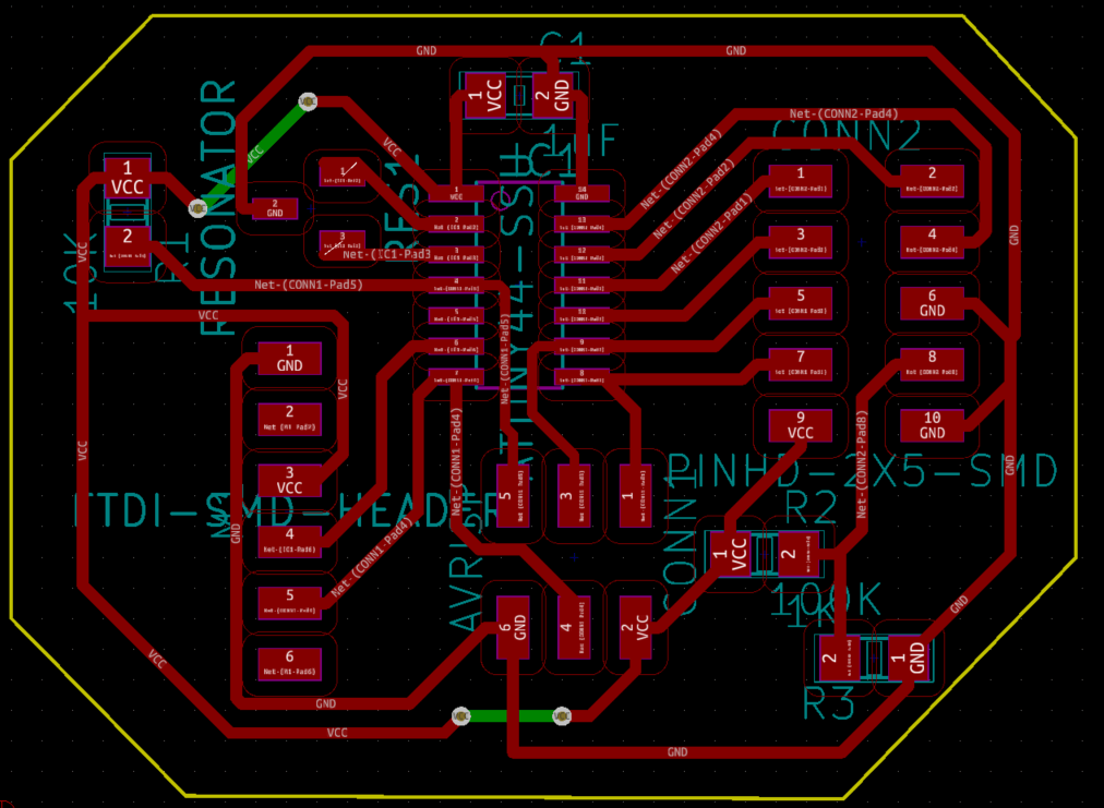
Because of the size of the end mill, I had to change design rules:
- 0.7mm for clearance
- 0.42mm for track width
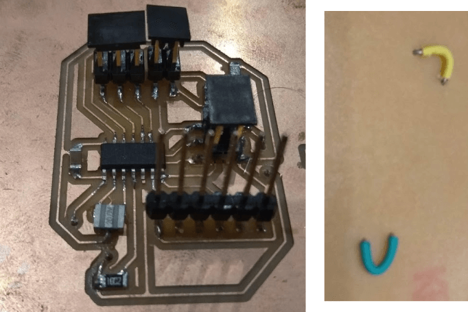
Because, with these rules, I couldn't get under components, I had to use back routes which are displayed in green. They are normally used for two sided PCB but, instead, I used jumper wire under the board.
The board milled fine and I was able to solder my components and wire. I didn't cut the edges because we experienced two times in a row the machine going down in Z and breaking the mill. We double checked the .nc file and nowhere a Z- was that deep. To avoid breaking more mills and until we find the reason, we didn't cutted the edges.
Testing the display
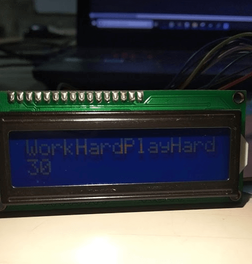
My first trial was to be able to send an helloworld message. Here is the code:
// include the library code:
#include <LiquidCrystal.h>

// initialize the library by associating any needed LCD interface pin
// with the arduino pin number it is connected to
const int rs = 5, en = 4, d4 = 0, d5 = 3, d6 = 1, d7 = 2; //These parameters depends on your pins connections
LiquidCrystal lcd(rs, en, d4, d5, d6, d7);

void setup() {
  // set up the LCD's number of columns and rows:
  lcd.begin(16, 2);
  // Print a message to the LCD.
  lcd.print("WorkHardPlayHard");
}

void loop() {
  // set the cursor to column 0, line 1
  // (note: line 1 is the second row, since counting begins with 0):
  lcd.setCursor(0, 1);
  // print the number of seconds since reset:
  lcd.print(millis() / 1000);
}
This code was working well. However, the screen backlight was very low. This, apparently, could be improved with a potentiometer
Receving chess moves
Work in progress. I manage to receive chess moves with LichessAPI. I now have to work on how to send them through serial port.