Reading the Datasheet
Summary
- Reading the Datasheet
- Programming the Atiny44a
- Add the Library into Arduino Ide https://raw.githubusercontent.com/damellis/attiny/ide-1.6.x-boards-manager/package_damellis_attiny_index.json
- Board Atiny 44
- Processor Attiny 44
- Clock 20mhz external
- Programmer UsbtinyISP
- Programming the Hello Word Board
- Blink/ Pwm1/ Pwm2
- Serial Communicatin with Hello World
Reading the Datasheet
I started out by reading the ATTiny 44 datasheet as it is the microcontroller we will be using in our boards here in FabLab Suriname. It is a "High Performance, Low Power AVR® 8-Bit Microcontroller". I actually never read these datasheet before programing my microcontrollers because I find it too much information so I google the specifics as I go along but maybe this is a better approach and it might save me alot more time by taking the time to read over the datasheets before getting startedAVR Architecture
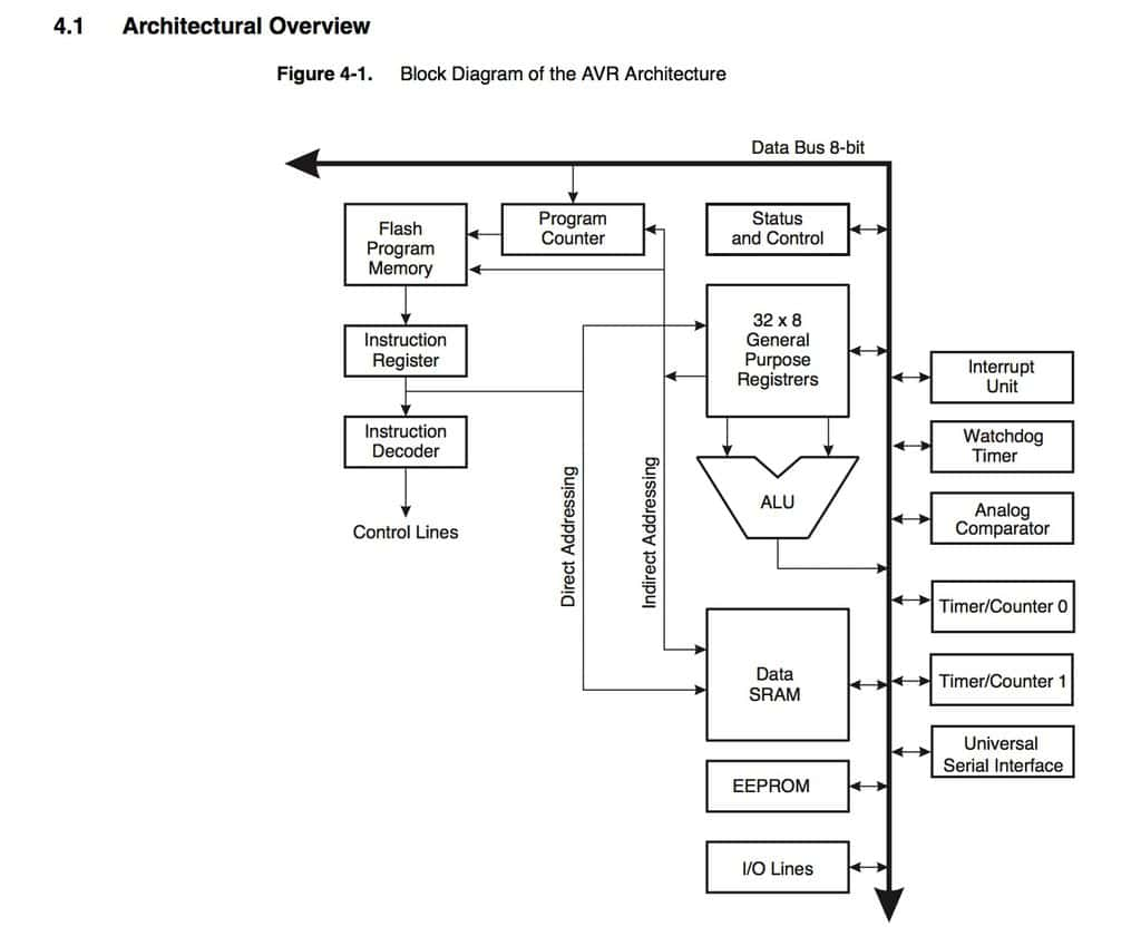
The datasheet included 27 chapters and 229 pages long and very informative. We will be using the attiny 44a microcontroller. I want to try and blink the led I built in my pcb - to use pwm to also control the brightness -to program the hello world board via avrisp- and to program the helloworld board via FTDI connector so I specifically paid more attention on the sections of the datasheet relating to what I wanted to acheive this week because the datasheet was quite long. A little overview of the attiny 44a datasheet is below.
The atiny 44a is a high-performance, low-power Microchip AVR RISC-based CMOS 8-bit microcontroller
Combines 4KB ISP flash memory,
256-Byte EEPROM, 256B SRAM,
12 general purpose I/O lines,
32 general purpose working registers, an 8-bit timer/counter with two PWM channels, a 16-bit timer/counter with two PWM channels,
Internal and external interrupts, an 8-channel 10-bit A/D converter, a programmable gain stage (1x, 20x) for 12 differential ADC channel pairs,
Programmable watchdog timer with internal oscillator,
Internal calibrated oscillator, and three software selectable power saving modes.
Note:By executing powerful instructions in a single clock cycle, the device achieves throughputs approaching 1 MIPS per MHz, balancing power consumption and processing speed.
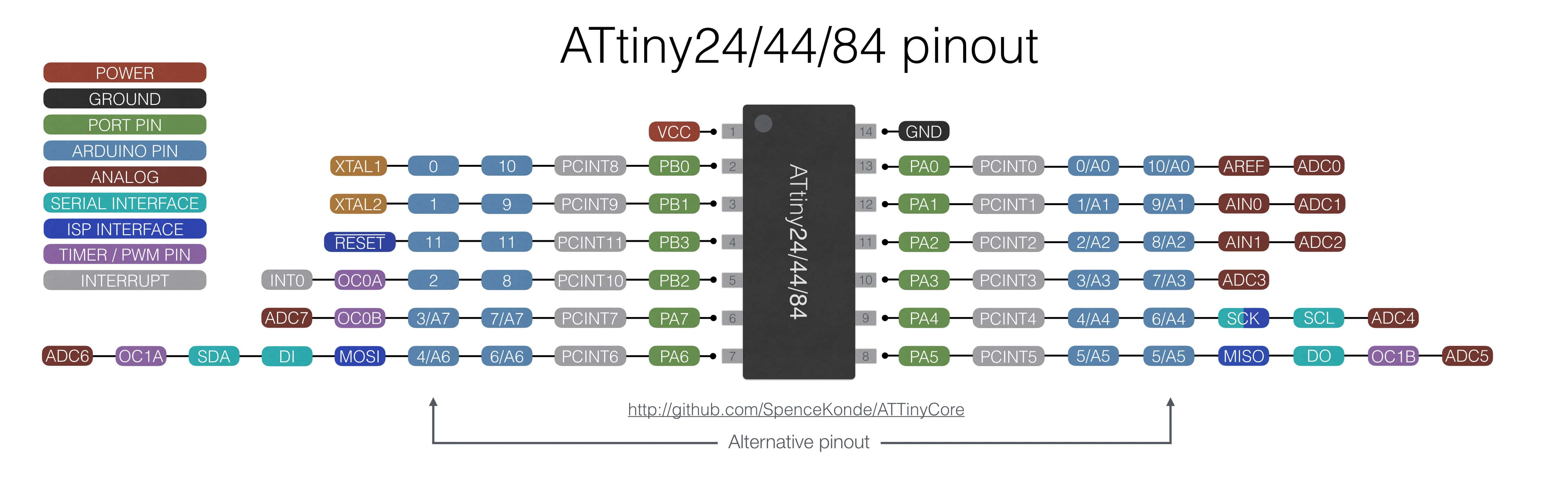
Pin Configuration
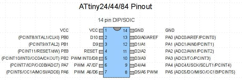
For programming any board we need to include these pins in our board. Some notes to understand the ISP and Headers
Avrisp
MOSI : Master out Slave in - This pin is used to transfer data from computer to the microprocessor
MISO : Master in Slave out - This pin is used to read data from the microprocessor
RST : reset pin - This pin is used to reset the microprocessor
SCK : clock - Clock signal is supplied with help of this pin
VCC : Voltage supply
GND : Ground
Header Connectors
RTS: Request To Send Control Output / Handshake signal.
RXD : Receive Asynchronous Data input.
TXD : Transmit Asynchronous Data output.
VCC : Ground
CTS :Clear to Send Control input / Handshake signal.
GND : Ground
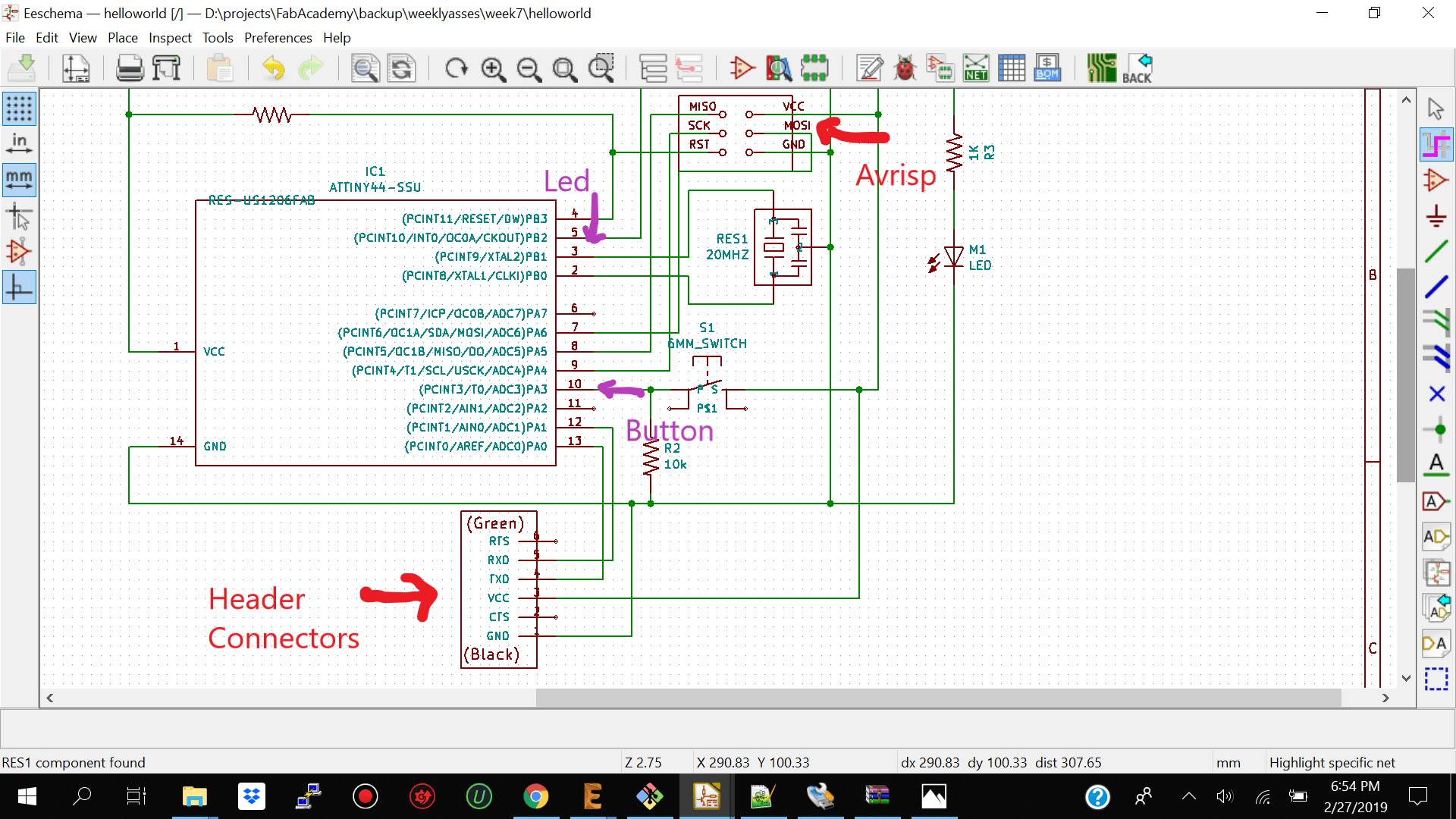
Based on the pinouts from the datasheet I selected for my led to be connected to attiny pin 5 which is also pwm pin and which maps to pin 8 on the arduino ide.
What I would like to learn more about
I woul like to learn more about the limitations of the attiny 44a 45 and 85 relating to processing power and memory capacity because recently I have realized that the attiny 45 is much smaller but it has less flash memory than the attiny 44a. I would also like to take some more time to understand The Parallel Instruction Fetches and Instruction Executions. How the CPUs instruction cycle is executed and instructions are processed. I would also like to understand more about how to limit power comsumption and putting my microcontroller in sleep mode when working with the avr microcontroller. I will need to integrate sleep more and limit power consumption when using wifi for my final project.
Programming the Microcontroller
Programming the Atiny 44a Microcontroller using the Ardunino Ide
Blinking the Led
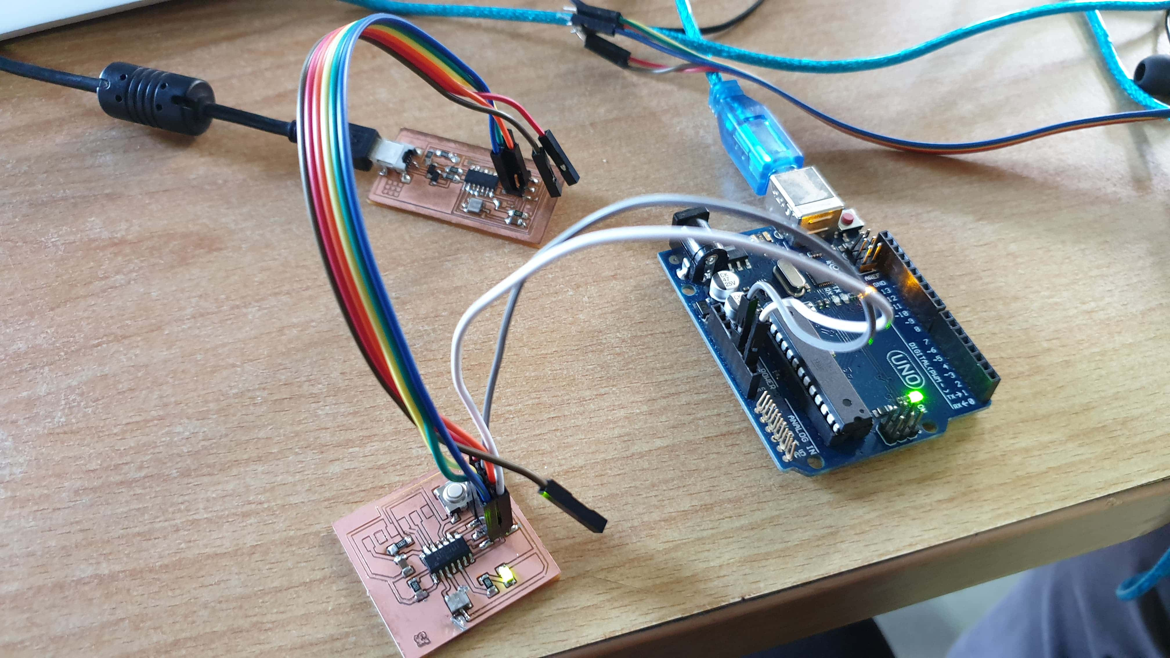
After soldering my pcb I now had to program it. I then connected my pcb to the previous fab isb which I made from week5. I connected it via isp.If you are going to make this connection make sure you have the mapping correctly you can follow the guid below.
After double checking the pinouts correctly you can go ahead and program your microcontroller board.I presume if you are using windows that you already have the drivers for the Fab Isp so when you check on device manager you should see either Fab isb or usb tiny.
Go ahead select the basic blink sketch and make sure you change the led pin according to yours mine was on pin 5 which mapped to arduino pin 8
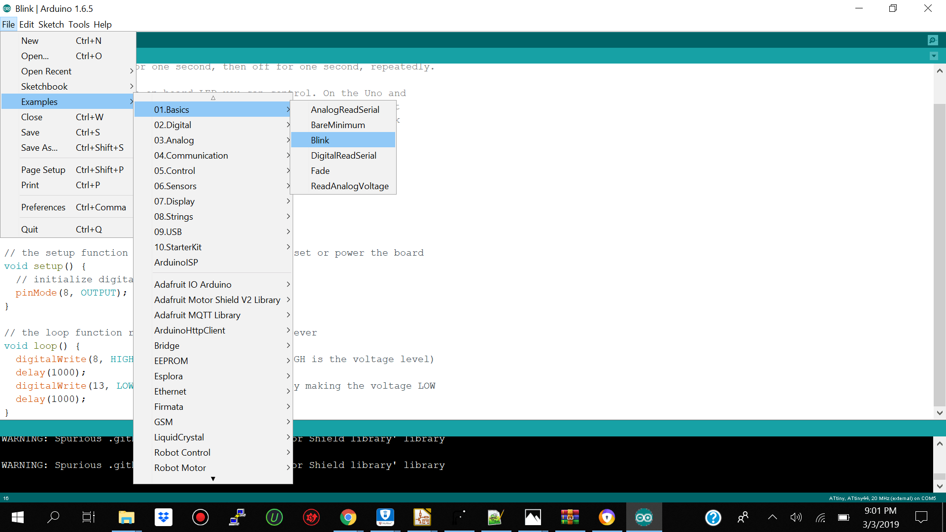
You should then open your arduino ide and add this link https://raw.githubusercontent.com/damellis/attiny/ide-1.6.x-boards-manager/package_damellis_attiny_index.json to your preference so that you can get the atiny board installed on board manager.
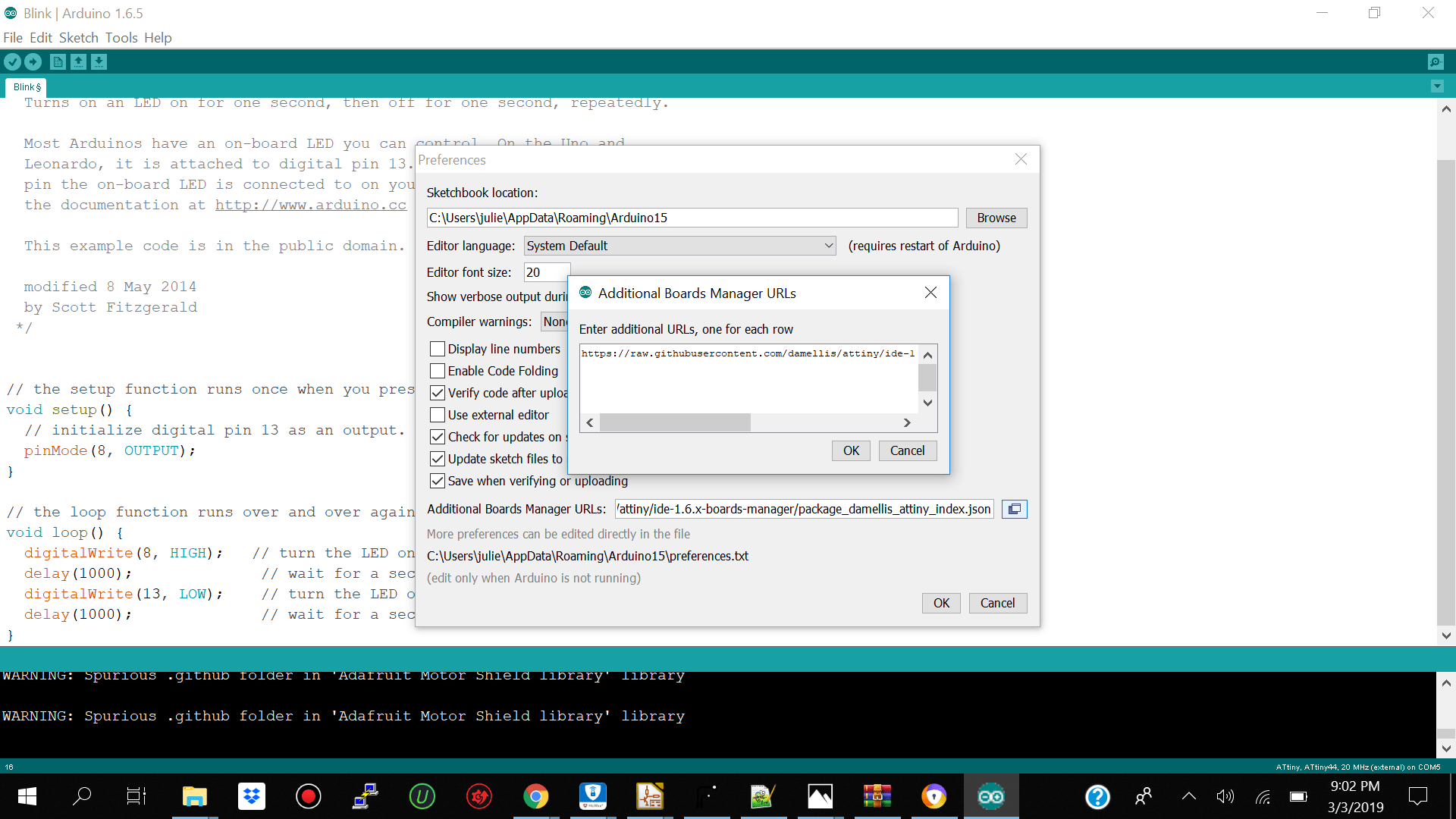
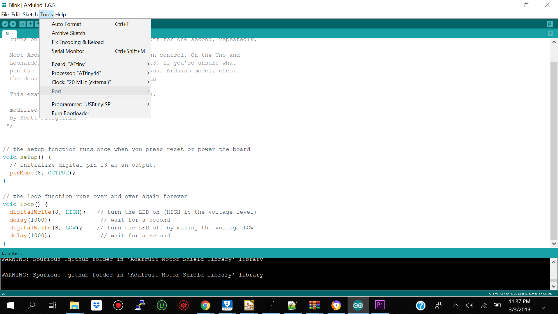
Once you have the board installed go ahead and select the Atiny board -- Processor Atiny44 (choose based on ur atiny) Clock 20mhz external Programmer-- Usbtiny and no need to select a port.
Go ahead and power your board and connect your programmer into your laptop and Run Bootloader.
After running bootloader succcessfully go ahead and upload your blink led sketch it should take 5 to 10 seconds to upload.
Lessons Learn
I did not have much issues when programming my hello world board the only issue which I had was not seeing the port on the arduino ide but I just press upload anyway and it worked.
One of the confusing things my classmates and I encountered was powering our hello world board when it was connected to our Fab isp programmer board. We initially took off both resistors from the fab isp and had to use the arduino to power the hello world board but then we realized if we kept one of the 0 OHM resistors we did not need to power the hello world board apart you can see the image below compared to the one above. Both works.
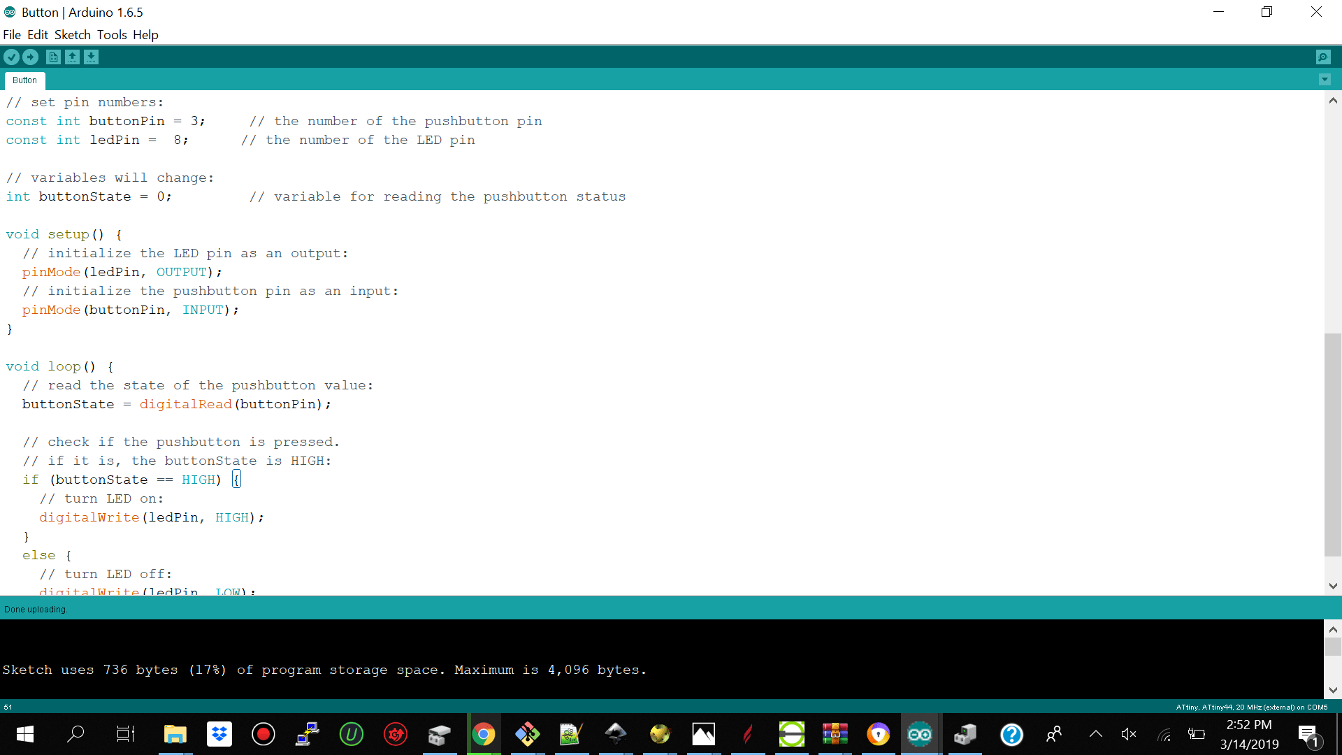
Using the Push Button to Blink the Led
The next test which I did was to upload a sketch for when I press on the push button the led turns on and when I release the button the led turns off. I checked the atiny pinout again and my button was on atiny pin 10 and arduino pin 3. I used the save arduino configuration as above for the board and the programmer and just uploaded my new sketch. It worked perfectly as you can see below.
Lessons
I reattached the 0 ohm resistor to my Fab isb board and powered my hello world board directly using the jumper cables so it looked cleaner.
Using the Push Button to play a PWM Sequence 1
The second example which I tried was to use the push button to brighten up the led by 2 pulses until it reaches 255 then return to zero or off. I realized that pulsing the button to get brighter by 2 was too low so in my below example second trial. I increased the brightness by 15 with every pulse.

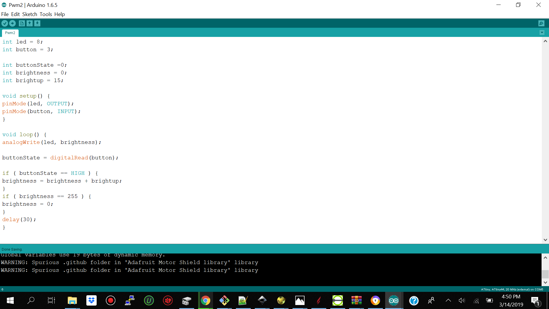
Using the Push Button to play a PWM Sequence 2
The third example which I tried was to use the push button to brighten up the led by 15 pulses until it reaches 255 then return to zero or off. I realized that pulsing the button to get brighter by 2 was too low I increased the brightness by 15 with every pulse.
Programming the Atiny 44a Microcontroller using the Atmel Studio
Hardware Setup
The next thing I tried was to use Atmel Studio to program my hello world board directly since I already burn the bootloader on the examples above.
We did not have header pins the pervious weeks so I had to solder the header pins to connect my ftdi cable. I used a normal 6 pin header cable and had to manuall cut and bend it to fit m pcb and solder it as you can see below.
I then went ahead to ftdichip.com to download the drivers for the cable and install it and then I see it connected as Serial Device (Com9) connected when I open device manager.
Atmel Studio
The environment which I tried next was Atmel Studio I downloaded it for windows 10 64 bit.
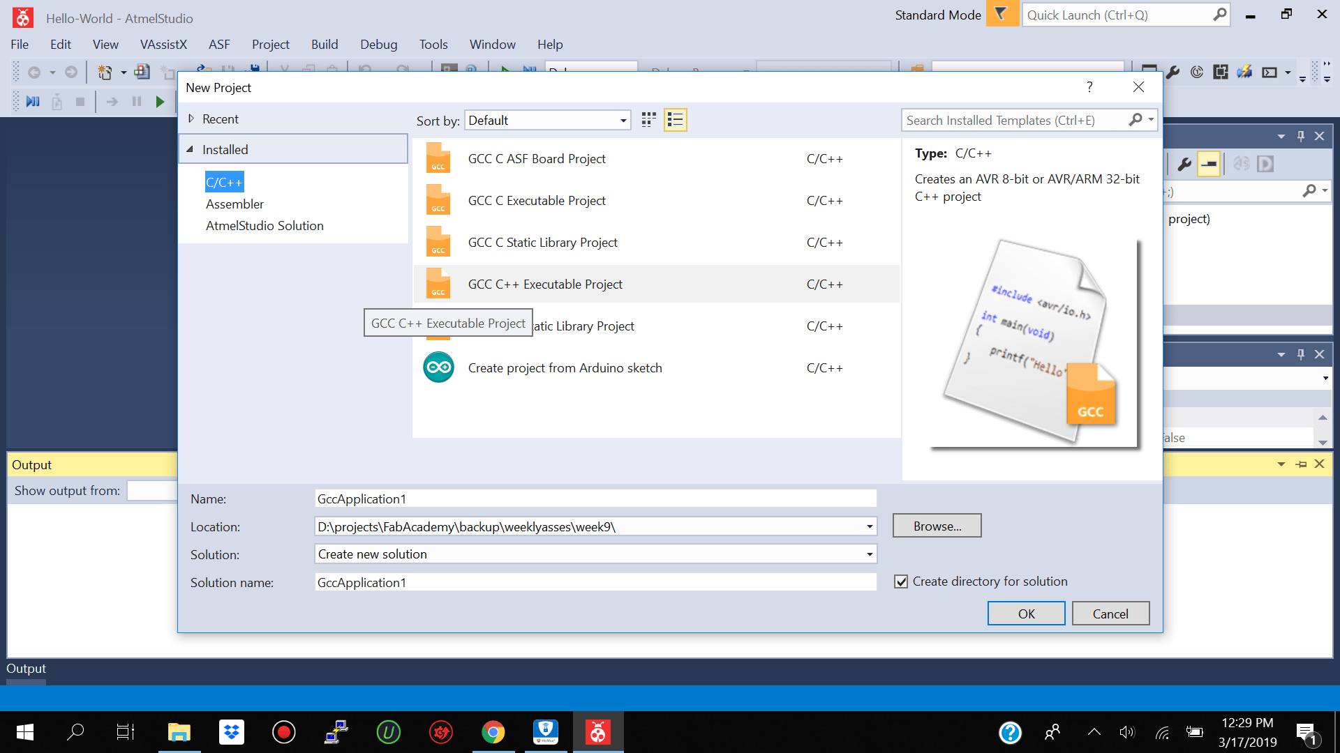
I already had avrdude from week5 installed so I did not have to reinstall it. After installing Atmel studio I went ahead and created a new GCC C++ Excutable Project.
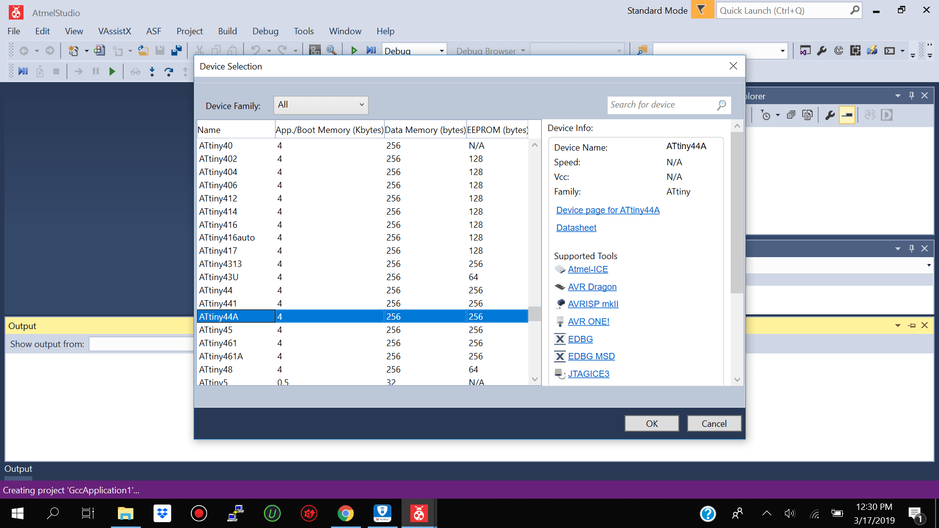
I then went ahead and selected atiny 44a for the device family because I will be using the atiny 44a microcontroller
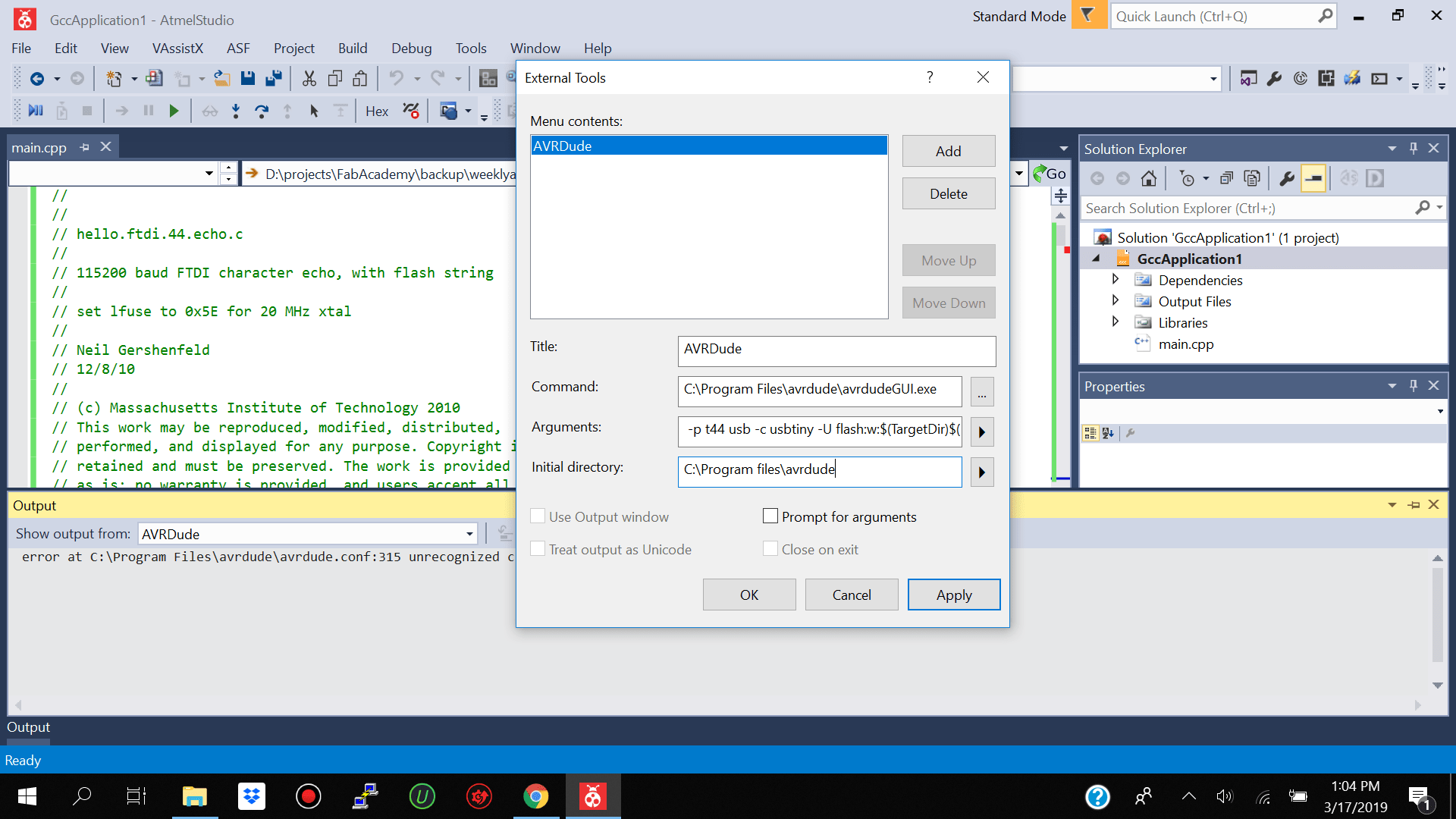
I then went ahead and added avrdude to my external tools on the atmel studio with the parmateters of
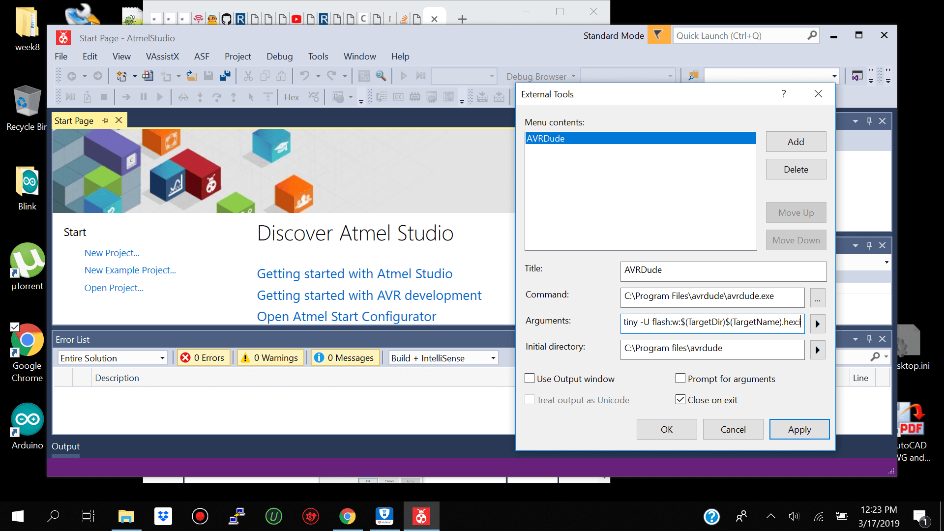
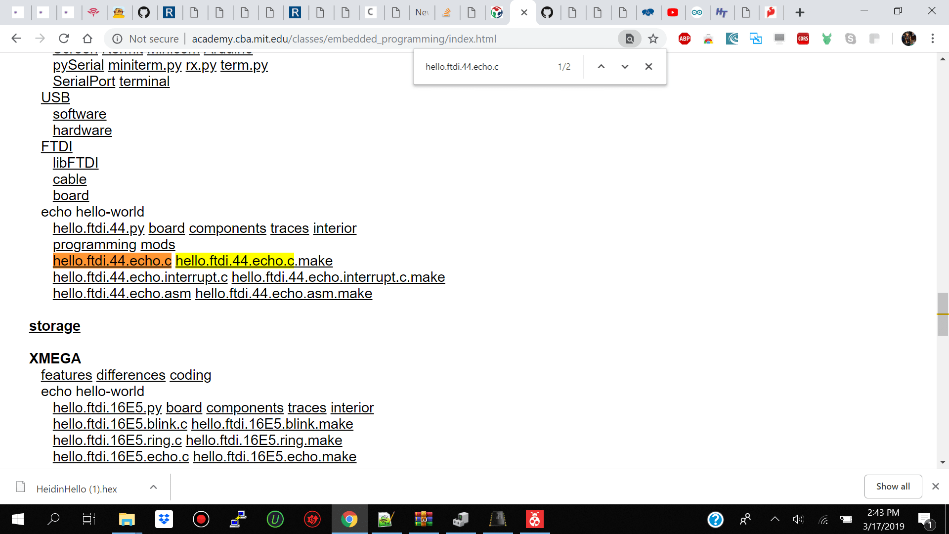
After configuring avrdude I went ahead and took niel's code from fab academy page for the hello world ftdi and paste it into my main.c file.
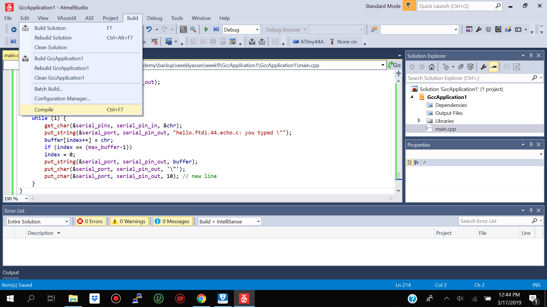
I then went and click on Build-->Comple to compile my code and it was done successfully
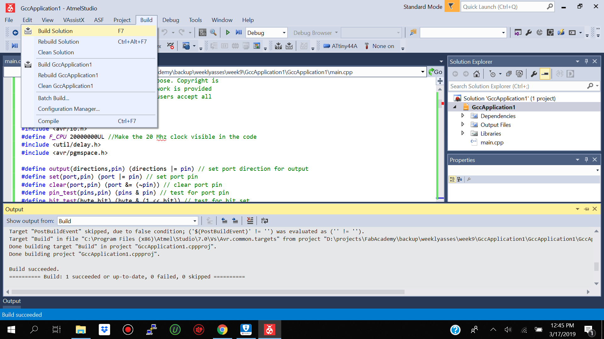
I then went and click on Build-->Build to build my complied code and it was done successfully
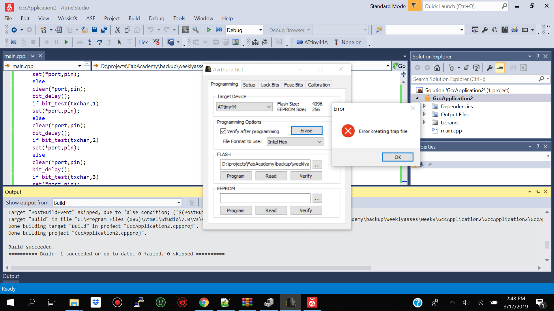
I then went to click on Tools-->Avrdude but avrdude comand prompt was not launching so I replaced the exe to gui and used the gui instead.
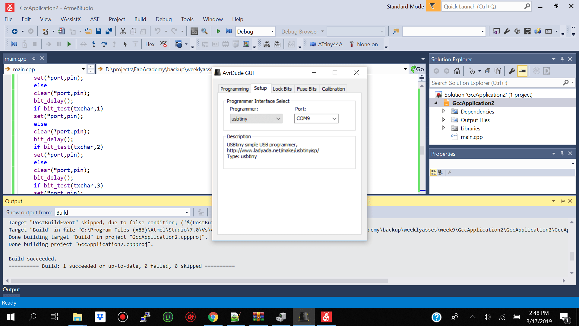
I then opened the gui and selected my
Programming
Setup
Programming the Hello World Board using FTDI Windows/ Raspberrypi/ Ubuntu
I tried programming the Hello World board directly using the Ftdi cable on windows using the arduino ide but that did not work. I kept getting usb device not found in the arduino ide no matter which programmer I used.
I initially thought it was a driver issue so I downloaded the FTDI chip Vrituam Com driver from ftdichip.com and installed it but I think there is an issue with the drivers when working on windows 10 because twice my pc crashed after installing the drivers.
I did some more research and they mentioned that the ftdichip drivers are outdated and I need to make some changes to the config so that it is compatible with windows 10 but I did not get around to doing that as yet
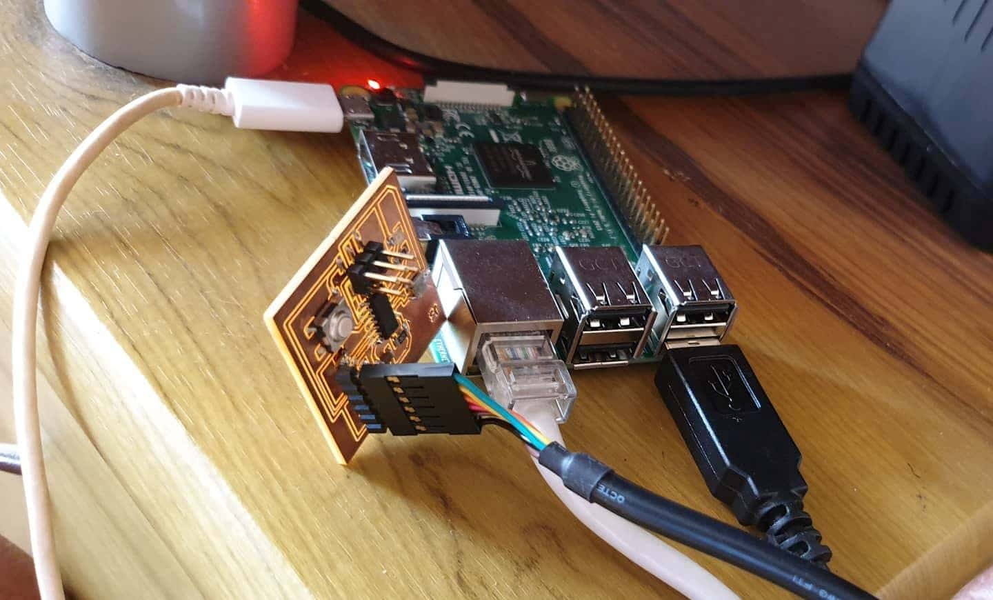
I also tried installing the arduino ide onto my rapberry pi and see if I can get it to work there then I received another error usb device not found. The research said to togle back and forth with the programmer from the dropdown on the arduino ide and use Arduino as ISP and that it should work but it still has not work for me.
My trainer had tried in class to program the hello world board connect to the fab isp using ubuntu but it also did not work.
Sending Data from Hello World Board over Serial Using Ftdi Cable and and Arduino Ide using Windows 10
The next test which I tried was to send some data over serial from the Hello World to the Arduino Ide. I initially tried a few samples but I kept getting the error "Serial was not declared in this scope I felt as if i was going insane".
I went over the atiny datasheet and I thought that the atiny had limited instruction sets and did not support the serial syntax of the arduino uno but after doing some more research I found out that the atiny board library which I was using for the arduino ide did not support serial so I need to get another one. The attiny core u here is the link http://drazzy.com/package_drazzy.com_index.json. After installing the board I seleted the same paramters as above. and was able to upload the code perfectly using the to read from serial.
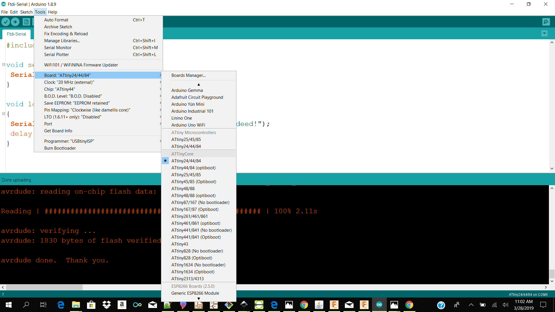
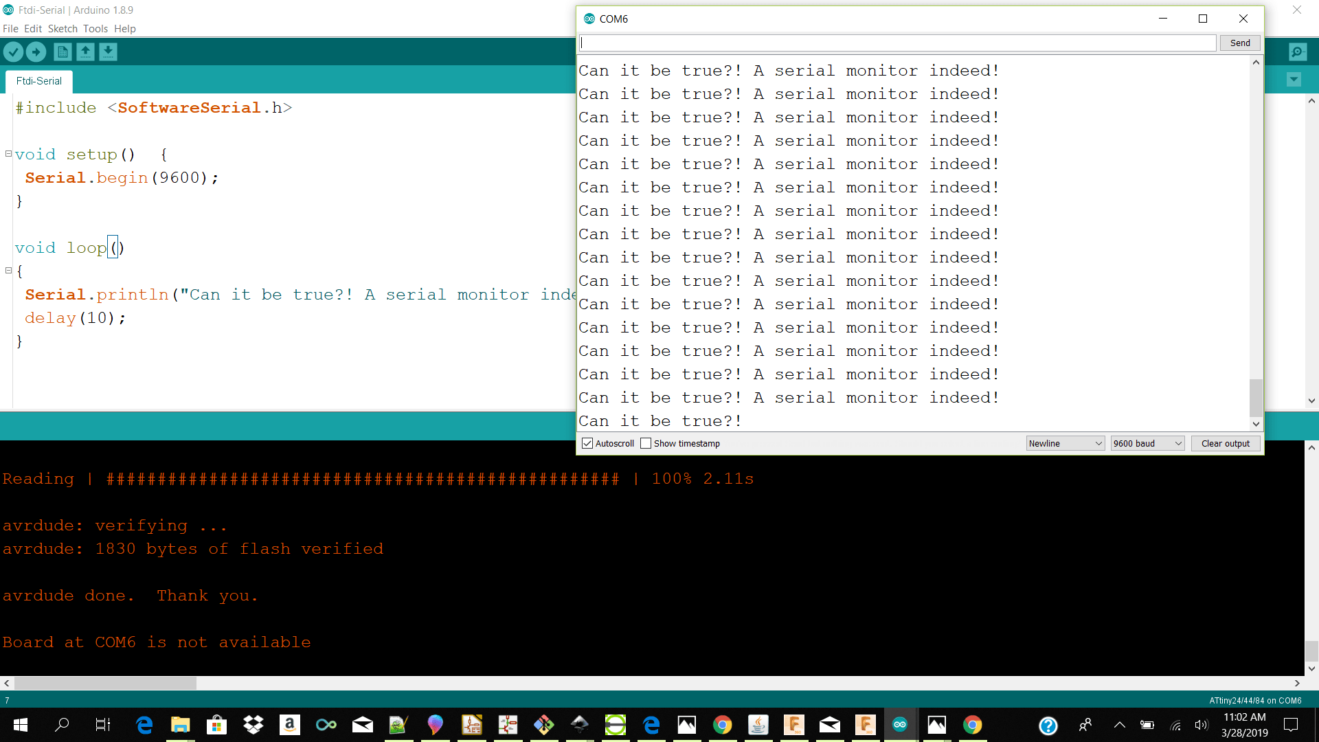
For the code I used softwareserial library to speak to the hardware of the atiny serial. I setup the serial to begin at baudrate 9600. When serial begins bring this line of text ("Can it be true?! A serial monitor indeed!") to serial monitor wait for 1 second and repeat.
Reference
Attiny Core Software Serial Library Code SampleLessons
Do not install the wrong drivers when using the ftdi chip connector make sure u install the drivers for windows 10 and not 7 because it caused my windows os to crash.
When installing the os for the raspberry pi 3 make sure you use the Os raspbian wheezy and not jessie because jessie does not boot on raspberry pi 3
When installing arduino ide on raspberry pi make sure you download the arm version 1.8.3 or older because the previous versions give me issues
Download Files Here
Arduino Blink Sketch
Arduino Button Blink Led Sketch
Arduino Button Push Led Pwm 1 Sketch
Arduino Button Push Led Pwm 2 Sketch
GccApplication.zip
Ftdi Serial Arduino IDE Serial Monitor
Contact Us
Where To Find Us
Paramaribo Suriname
Ethnalaan
50..