Summary
- Tests Run using the Shopbot PRSalpha and Stepcraft 2-300
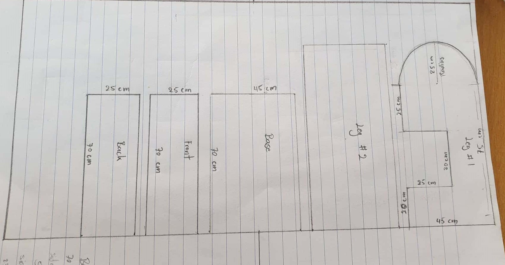
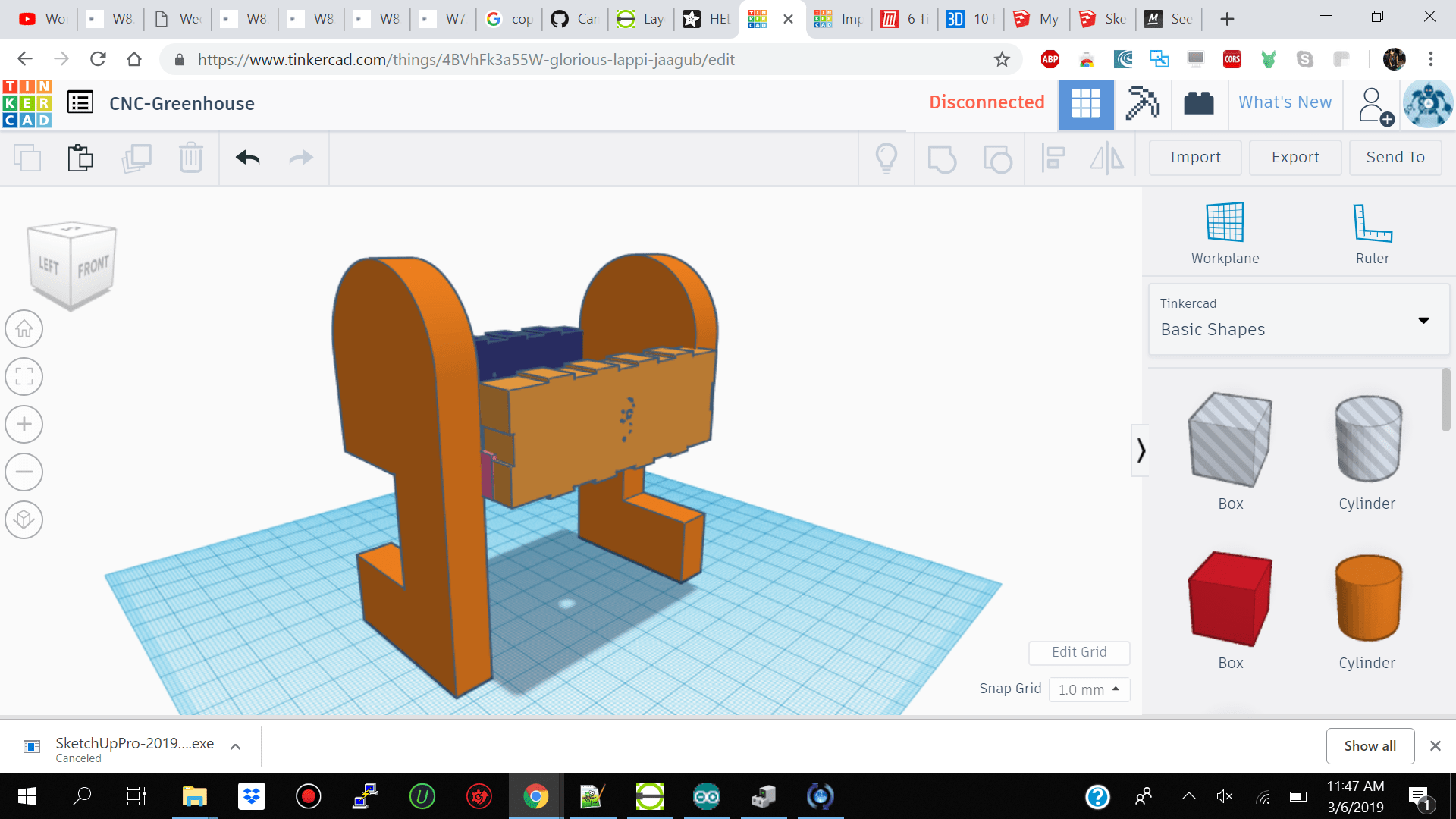
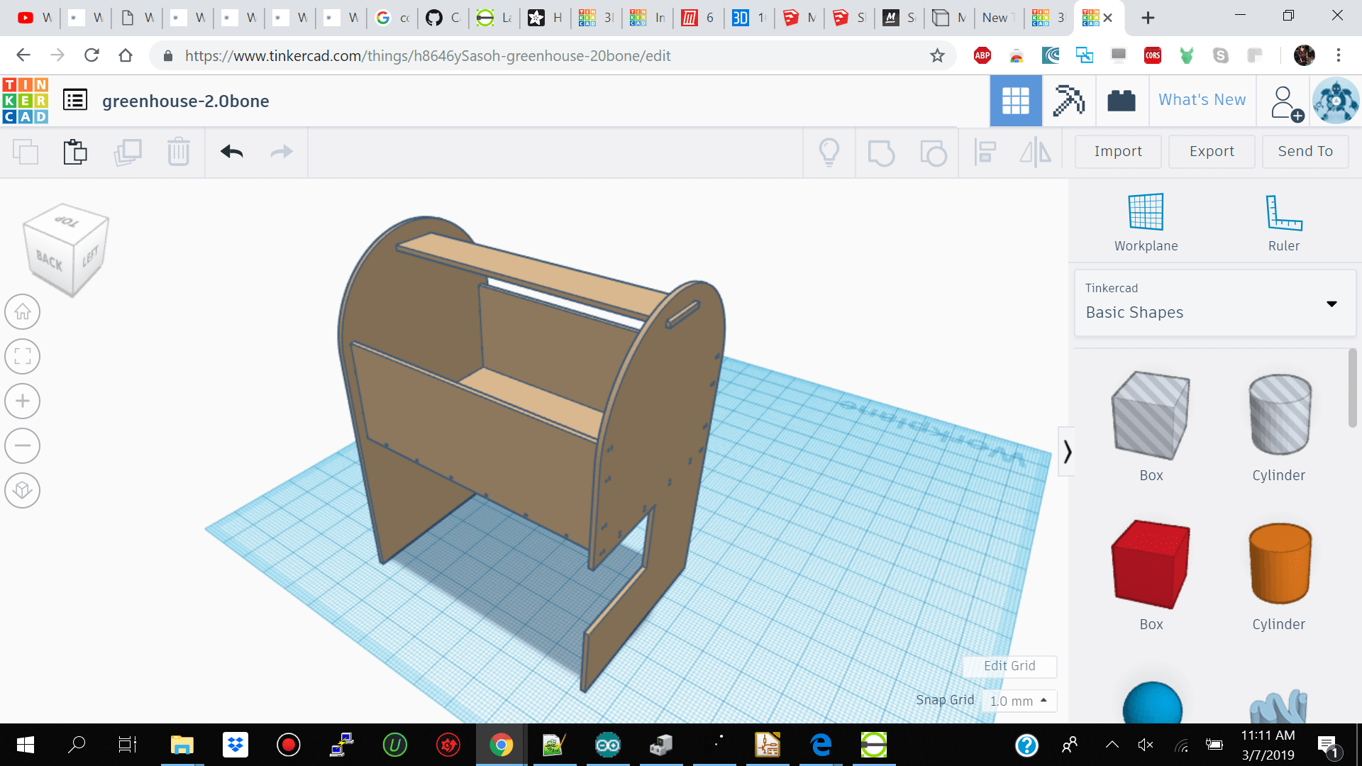
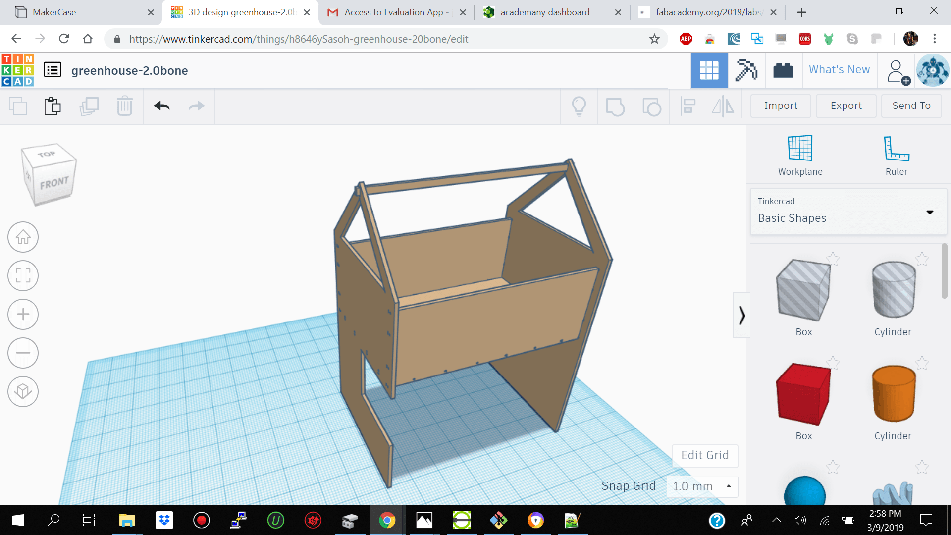
- Brainstorm and Design
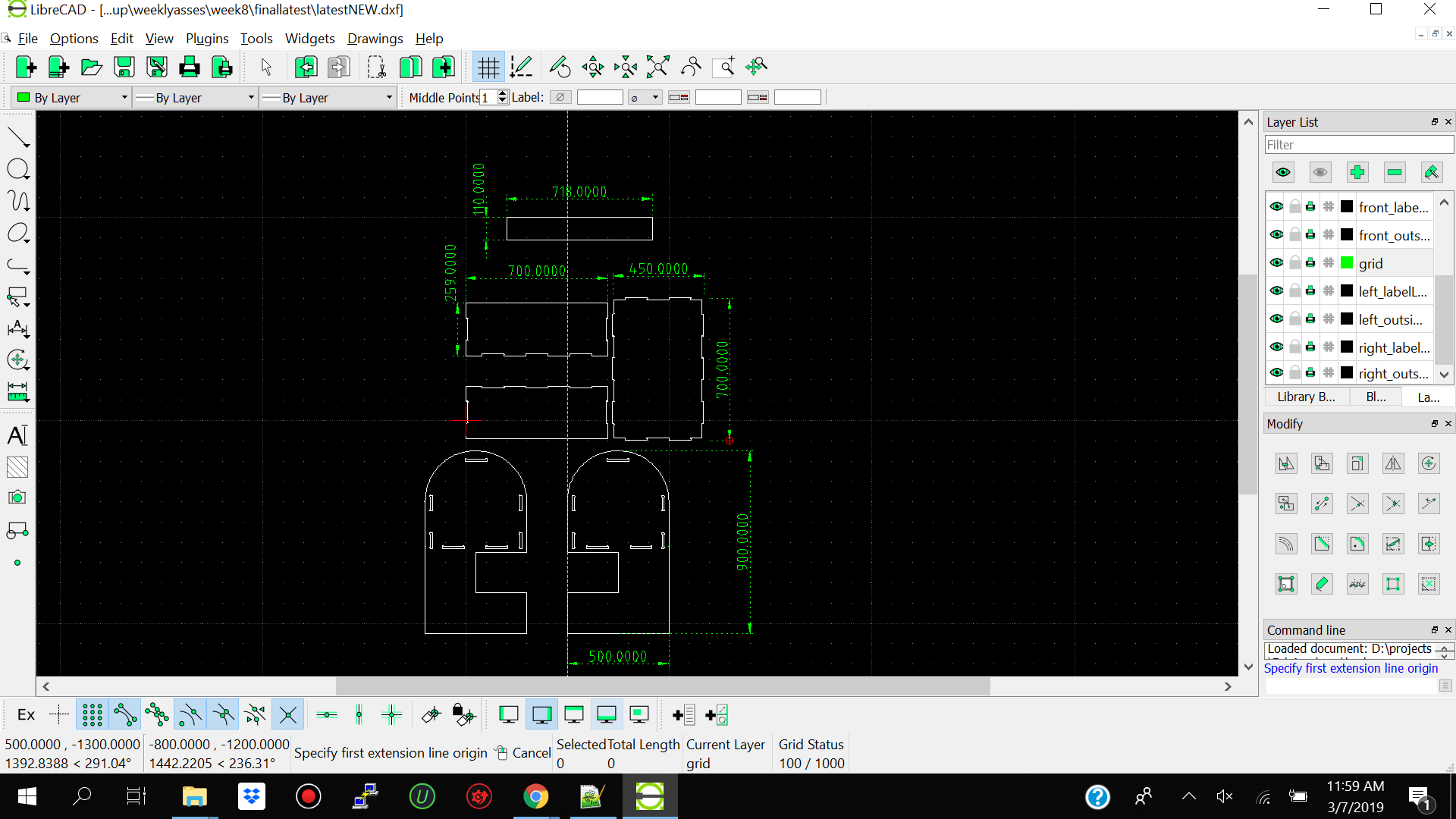
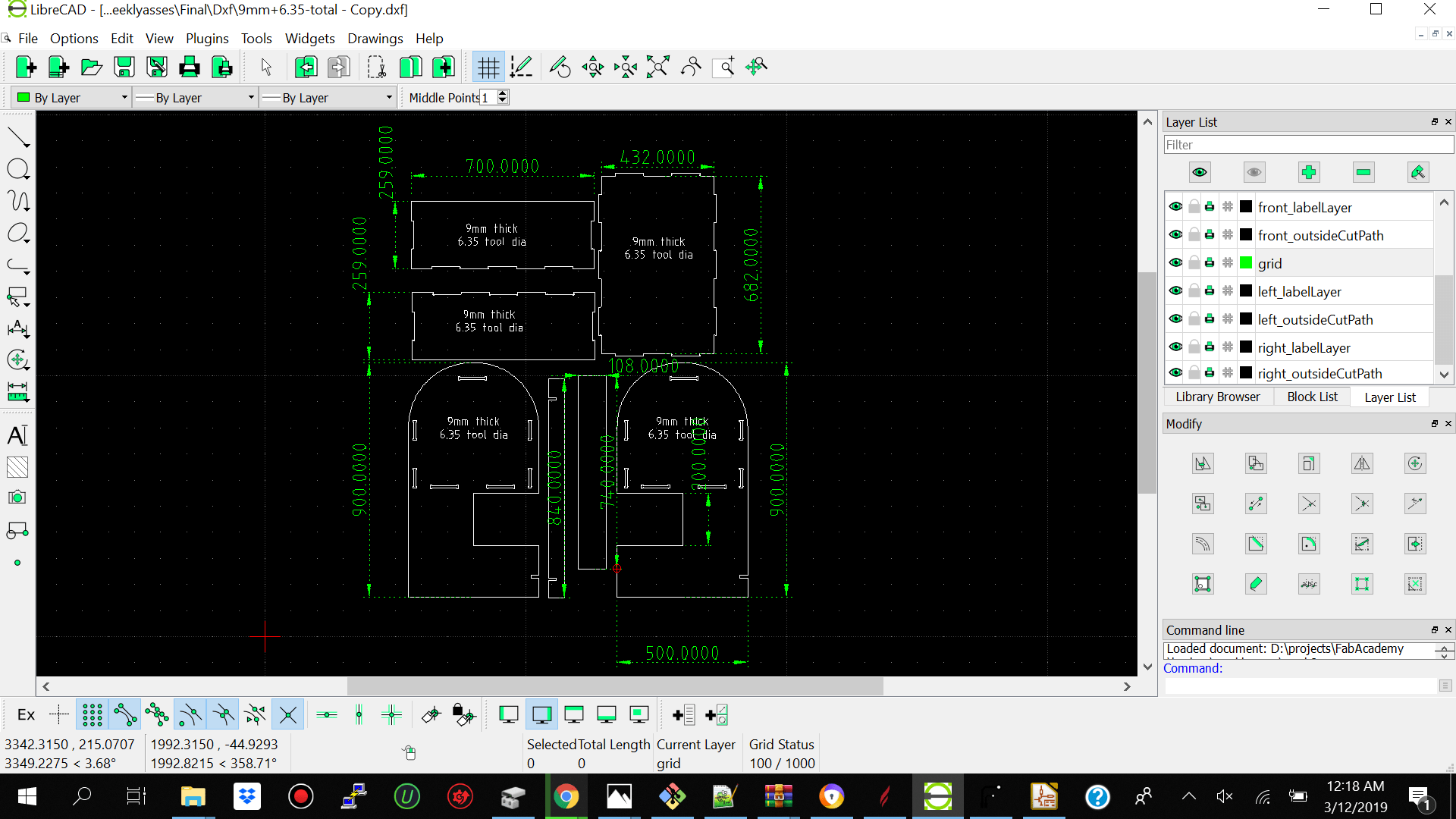
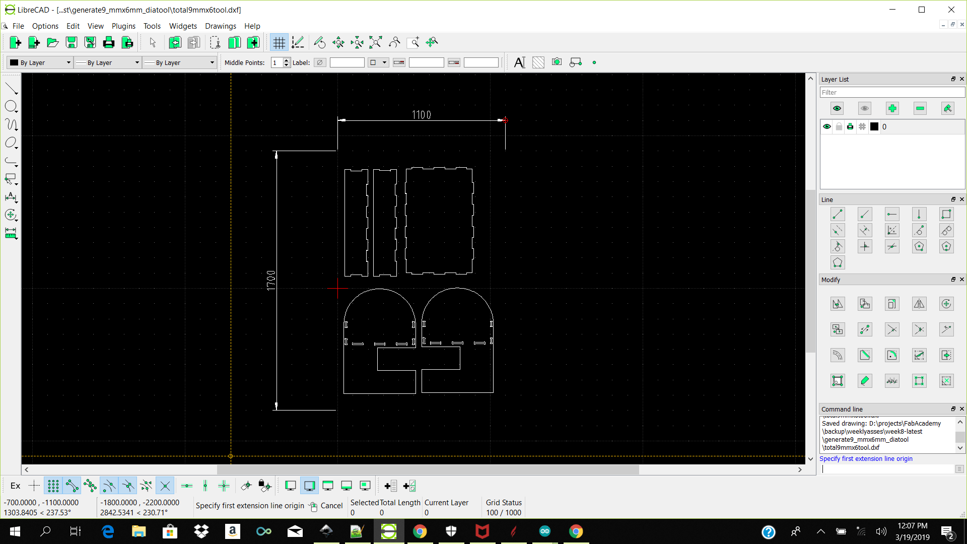
- Design In Librecad
- Options -->current drawing preference --> milimeters / General Scale 20 / Length Factor 1
- line - 2 points /horizontal /vertical
- circle- 2 points and center radius
- polyline- creating polyline from exsisting segments
- copy / duplicate
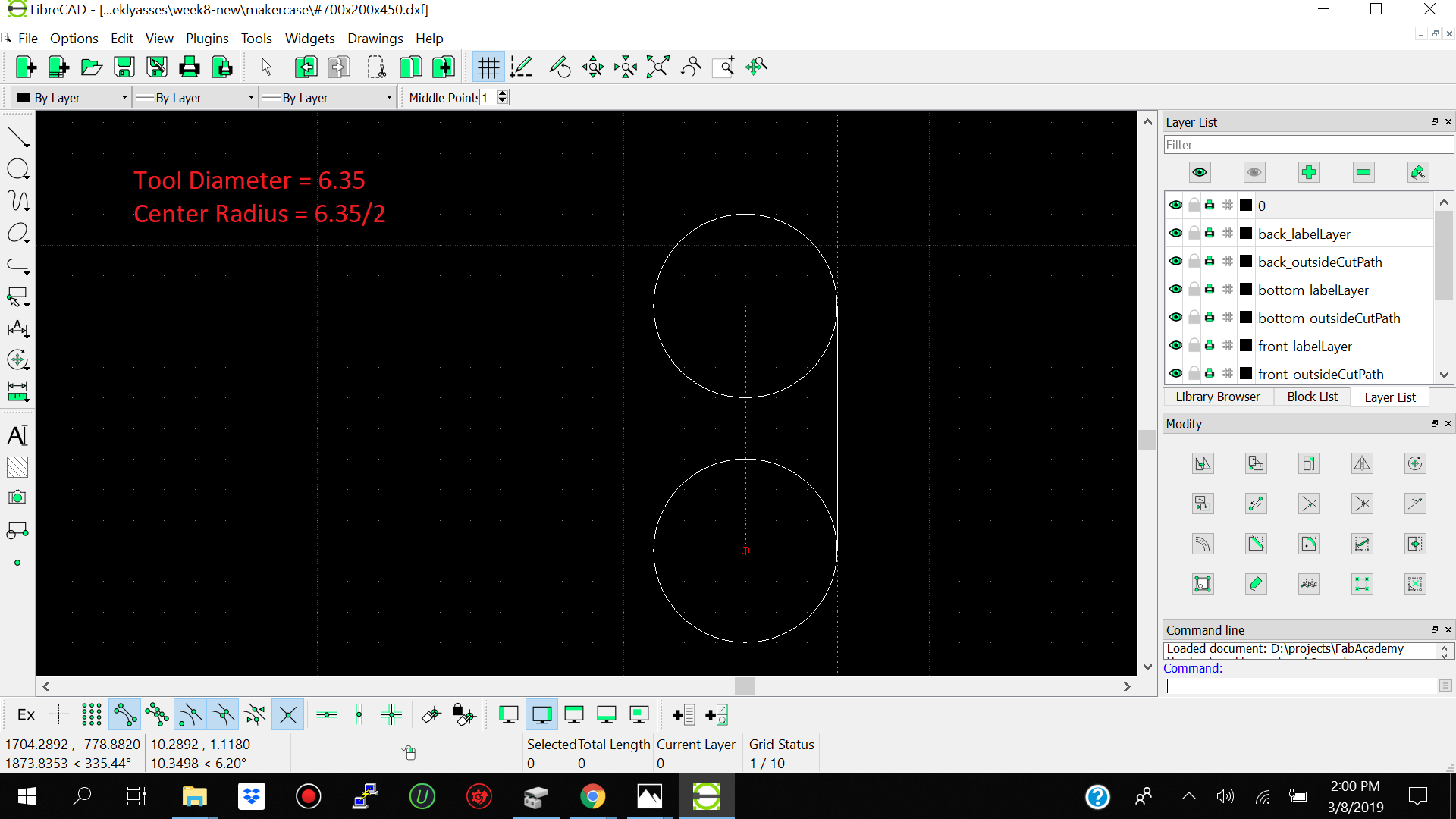
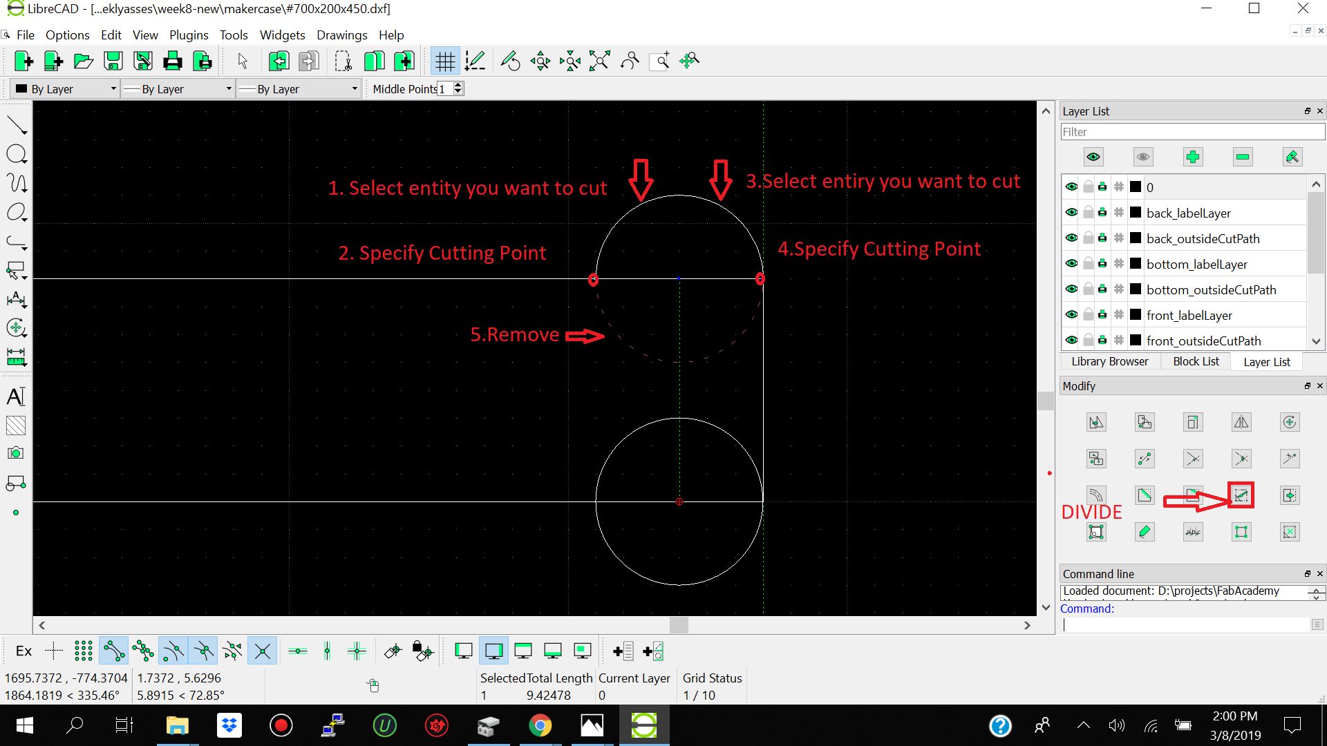
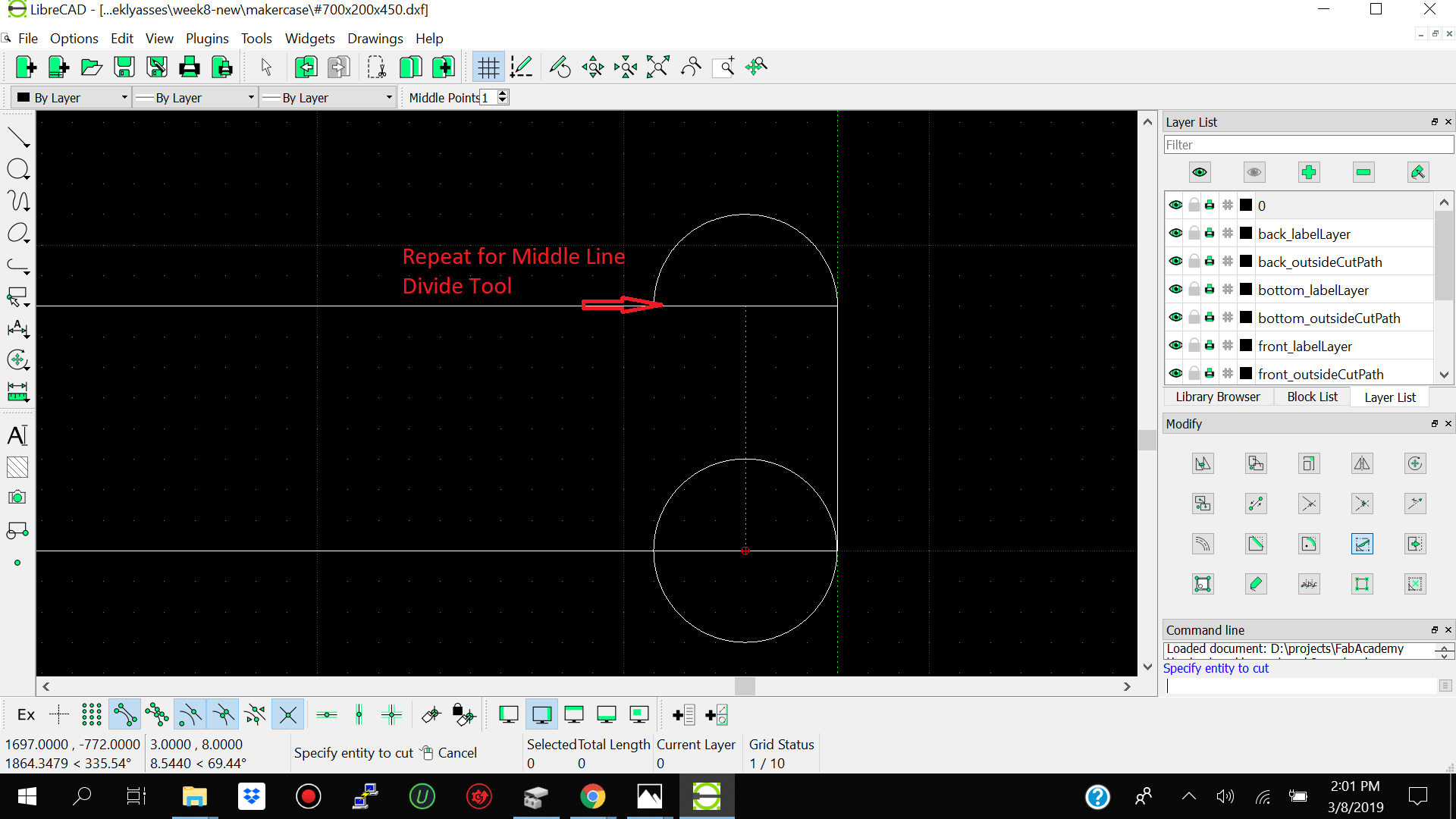
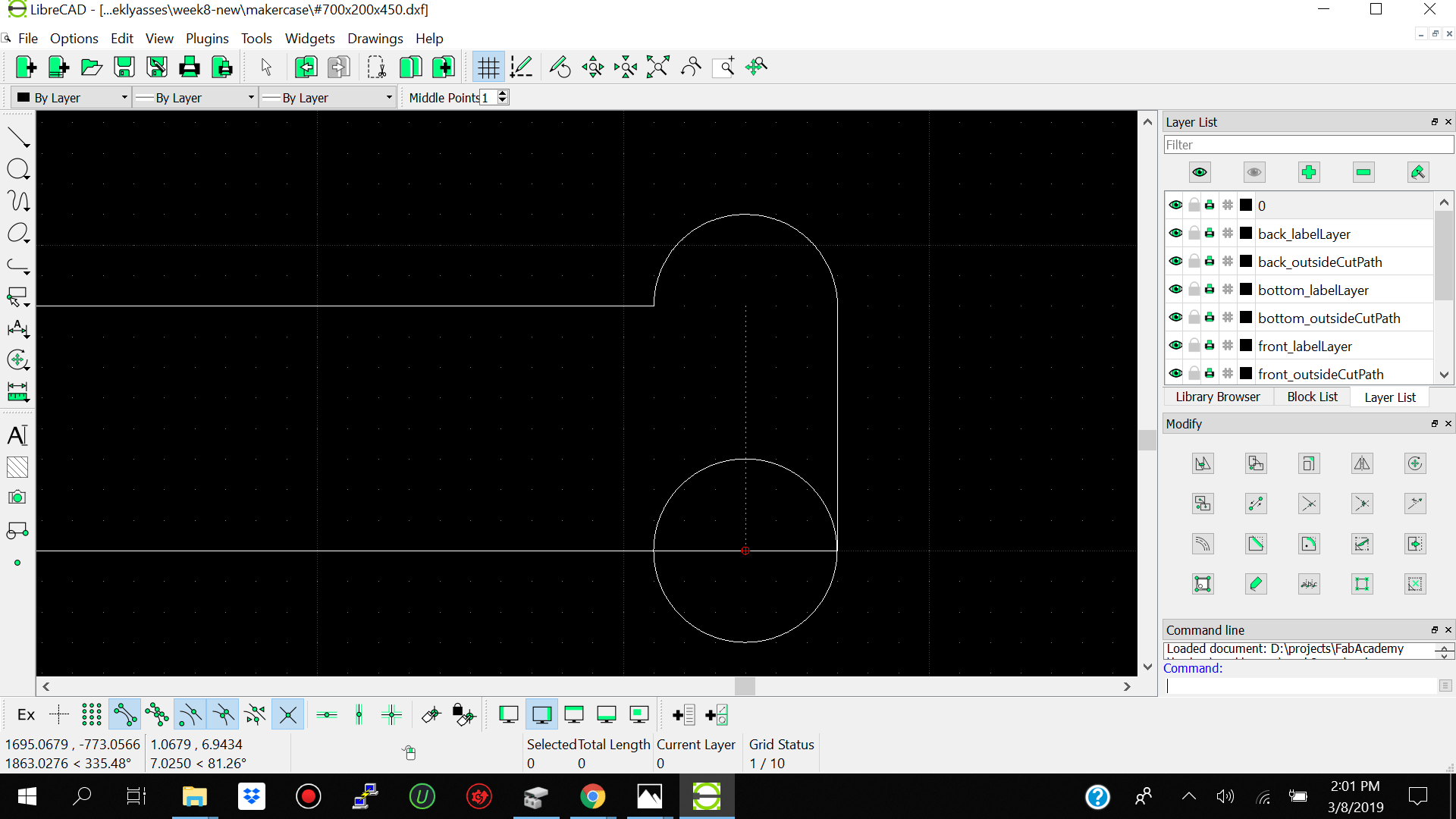
- divde for making the dogbones
- Shopbot Parameters
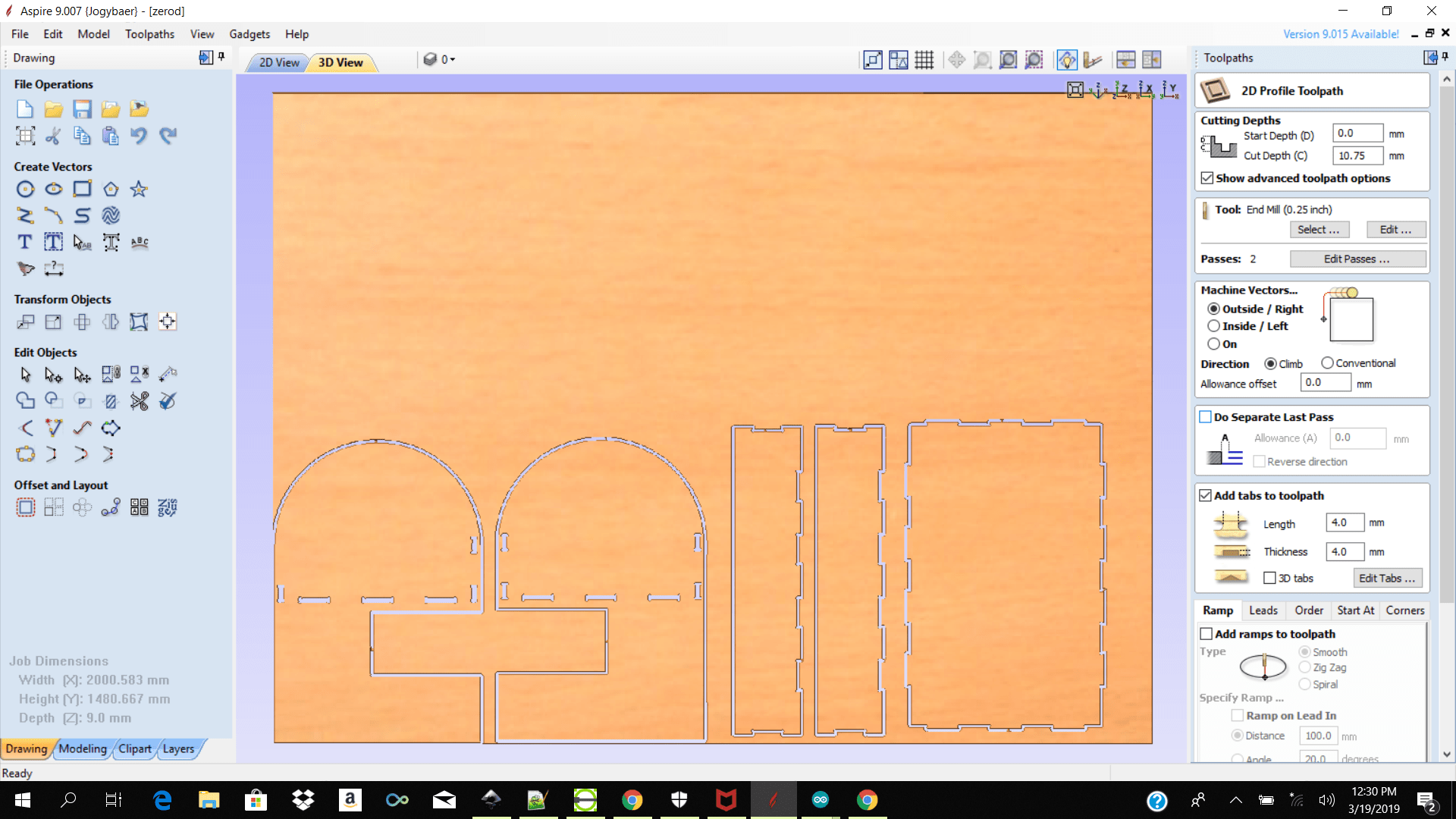
- Outside Cut
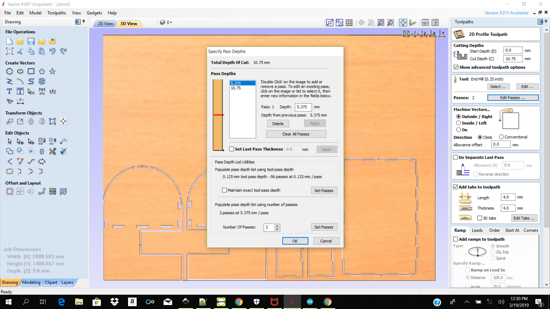
- Cut Dept 10.75 for 9mm material
- Passes 2
- Tool Dia 6.0
- Spindle Spee 14000
- Feed Rate 120.0 mm/s
- Plunge rate 15.0mm/s
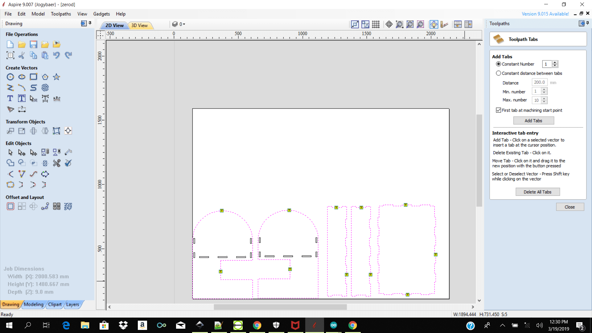
- Tabs
- Inside Cut
- Passes 1
- No Tabs
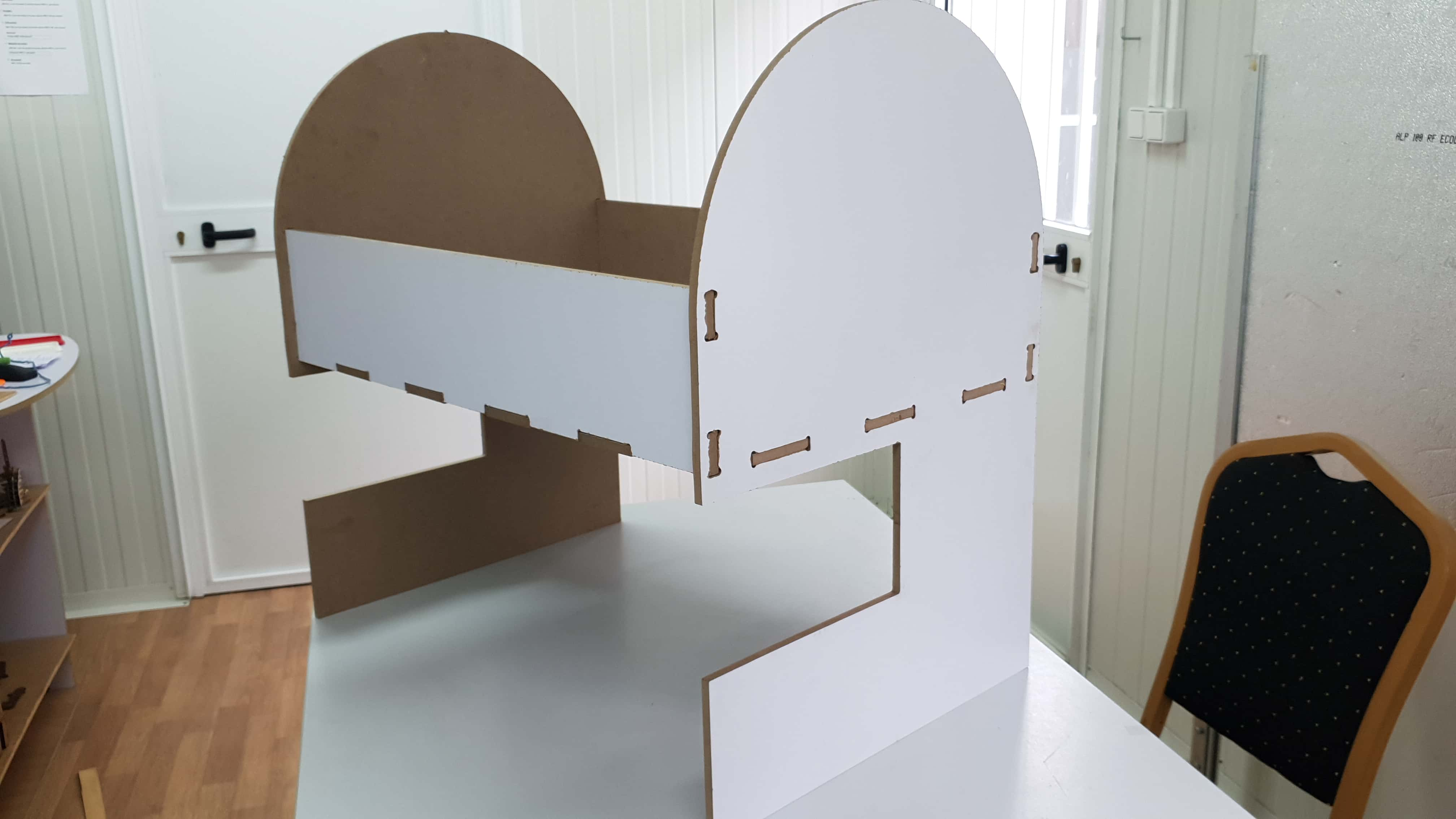
- Assemble
For this weeks assigmnent we had to use the cnc machine to make something big.The downside for us here in suriname was that initially we did not have access to a working cnc machine so we had to go back and forth between two semi avalible machines at two different locations. The stepcraft D840 at the iot lab and the Shopbot PRSalpha 96-48-8 at the fab lab suriname.
We started off doing our tests using the shopbot in the fab lab suriname.The first thing which we did was to buy our material we had 9mm plywood and 8.5mm mdf.
The next thing we did was get to know the Shopbot PRSalpha 96-48-8. We got guided through the physical setting and software set up of the shopbot before using it.
Before getting started using the stepcraft we had to keep in mind the safty rules before going in and getting busy. We had to make sure we had
After putting our safty gears on we went and select which material we wanted to do our test on. We started off using the 9mm plywood and tacked it in on the shopbot base plate.
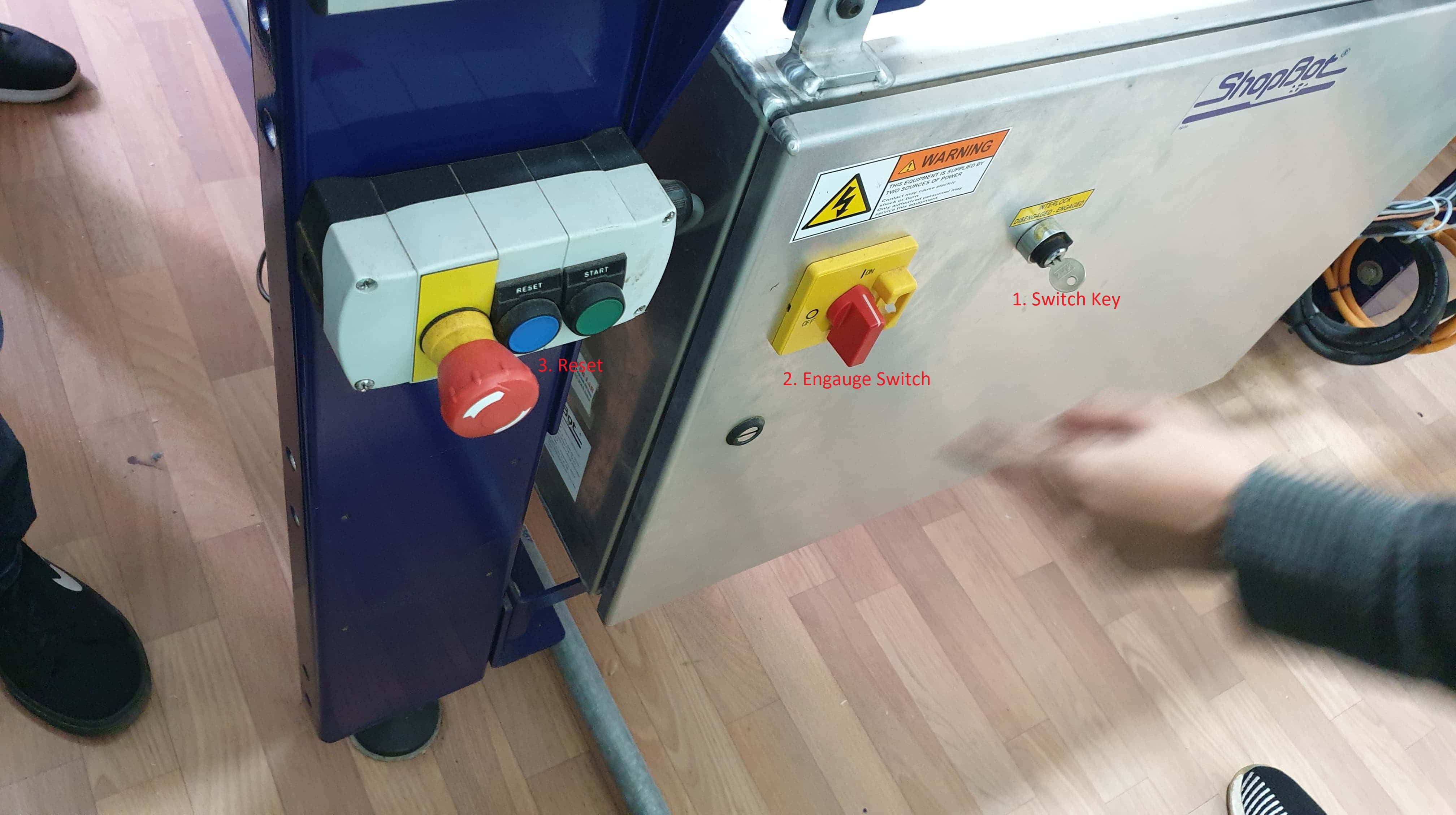
We were then guided by the fab lab suriname manager on how to go about starting the shopbot. We had to first go around to the left side of the shopbot and as you can see below first switch the key to the right , then switch the second lever to the right to engauge the machine then press the green reset button to rest the shopbot.
Shopbot Shopbot PRSalpha 96-48-8 Setup
Physical
Once the shopbot was physically ready we went to configure the software. For using the shopbot the recomented software to use by our lab manager was Vcarve or Aspire for converting our svg or dfx files into spb files and the Shopbot software for reading the spb file and turining it into coordinates to control and positon the shopbot.
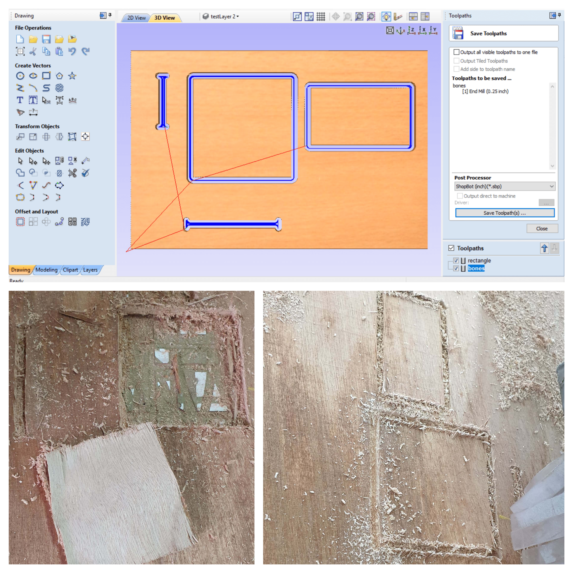
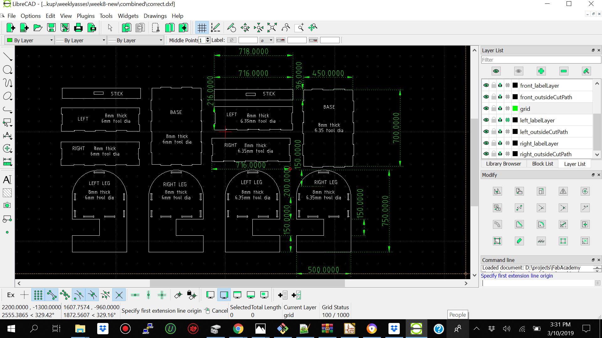
When using vcarve and aspire to impot my dxf file from librecad I initially had alot of issues because vcarve and aspire was reading lines that I could not see was there for example extra layers.It was making a mess of the preview cut. I then trouble shoot the problem and realized that when exporting my dxf file from librecad I had to make sure I did not have additional layers instead just one layer with my design and I also had to make sure I made polyline of each segment of my design so that all the lines were closed. Then when I went ahead and imported it into vcarve and aspire I had no problems.
I then went ahead and add my
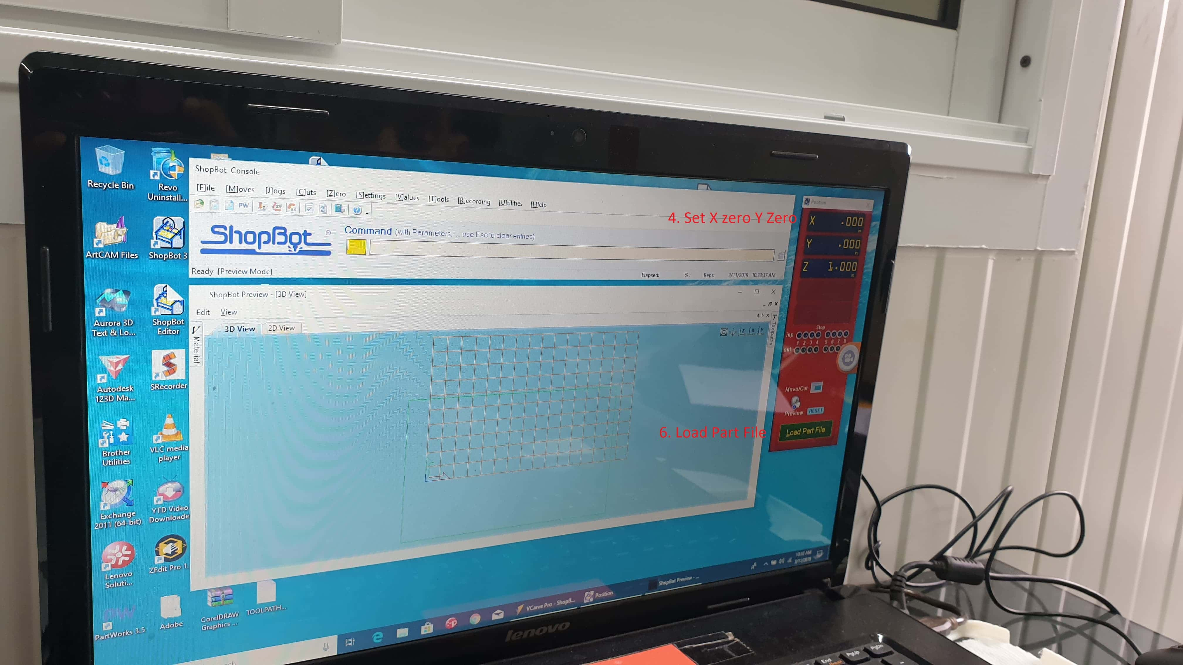
After exporting my spb file. I then went ahead and open the shopbot software and position the shop bot x and y position to 0 and under Cut I set it as home position.
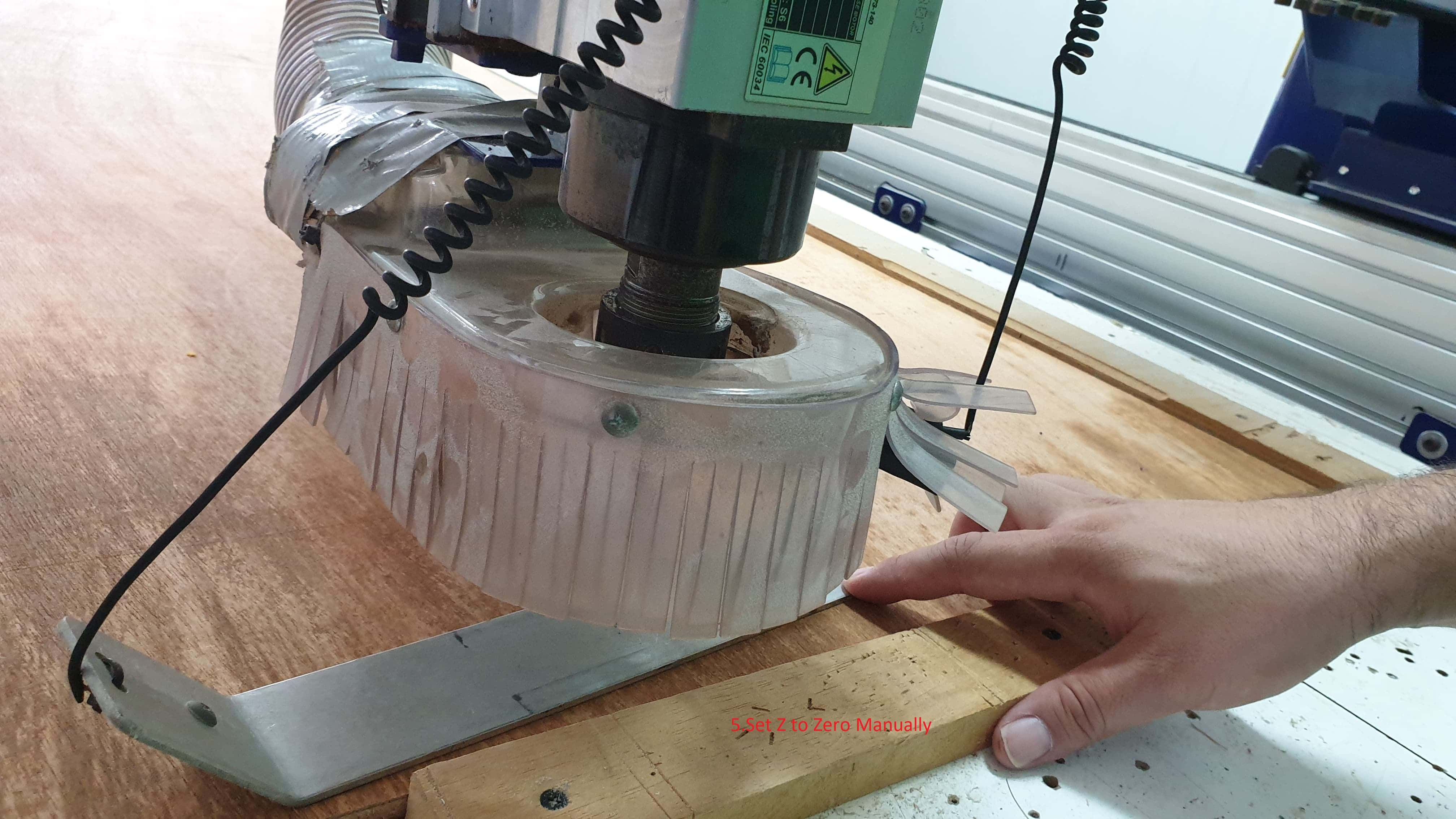
And also manually set the Z axis to zero. For setting the z axix to zero we had to take the silver plate put it on the base plate and connect the clamp to the spindle and via the software lower the spindle until it touches the plate and recalibrate.
Software
After the shopbot was ready I then had to navigate to my spb file and import it into the shopbot,
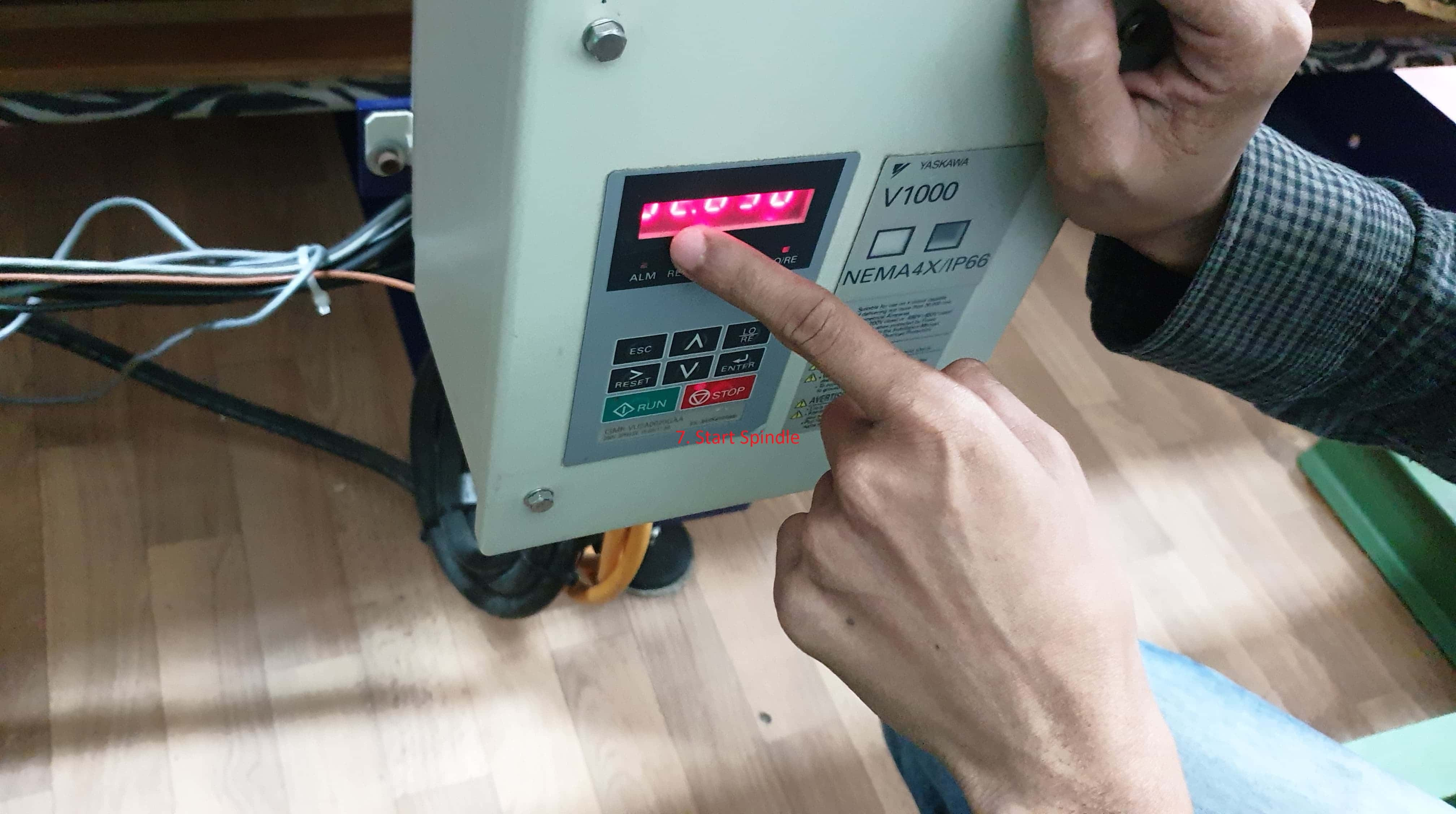
I then went around and turn the spindle on on the side of the shopbot using the green button on the box.
I then went back to the shopbot software and click start a popup with appear to confirm if you want to continue with the procedure. You then check with whoever is watching over the machine if its you or a collegue. Check if they are at a good distance from the machine and if they have their safty gear on and if they have the emergeny switch in their hand to push incase of emergency.
Then you go ahead and confirm and press start
Once your procedure is completed you can go ahead and add another partfile and repeat or you can change the zero position if you would like to do your second procedure on another zero position.
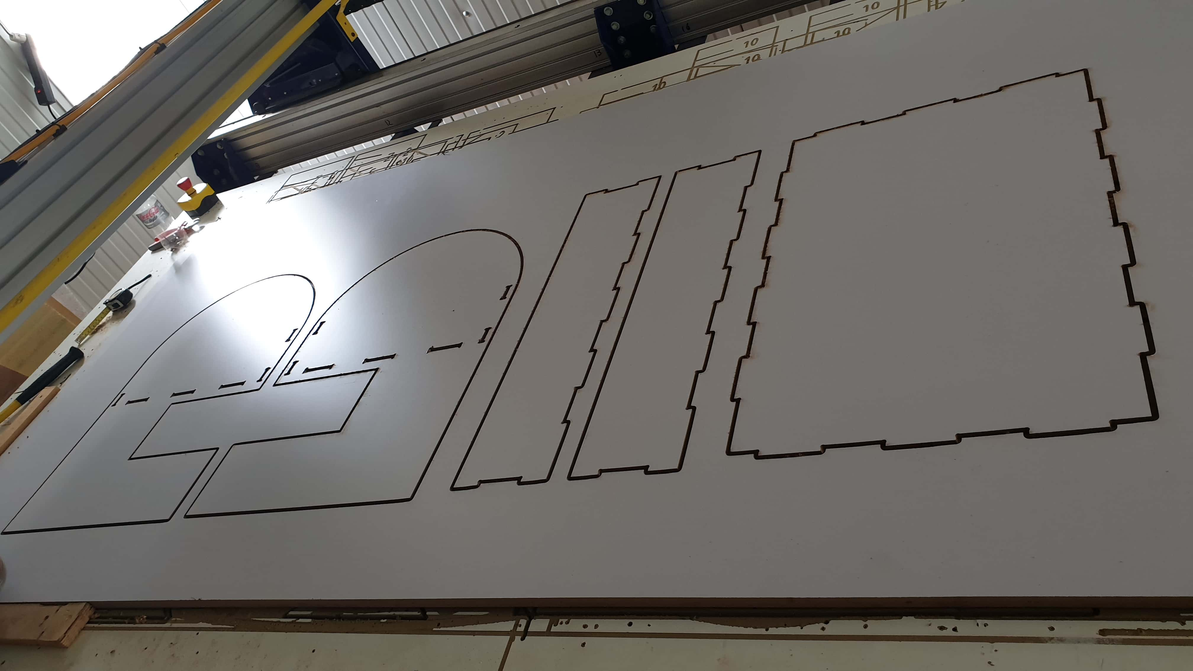
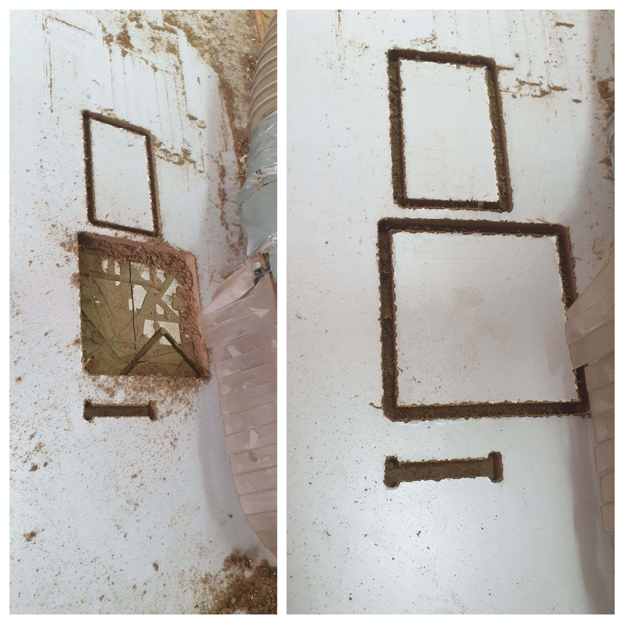
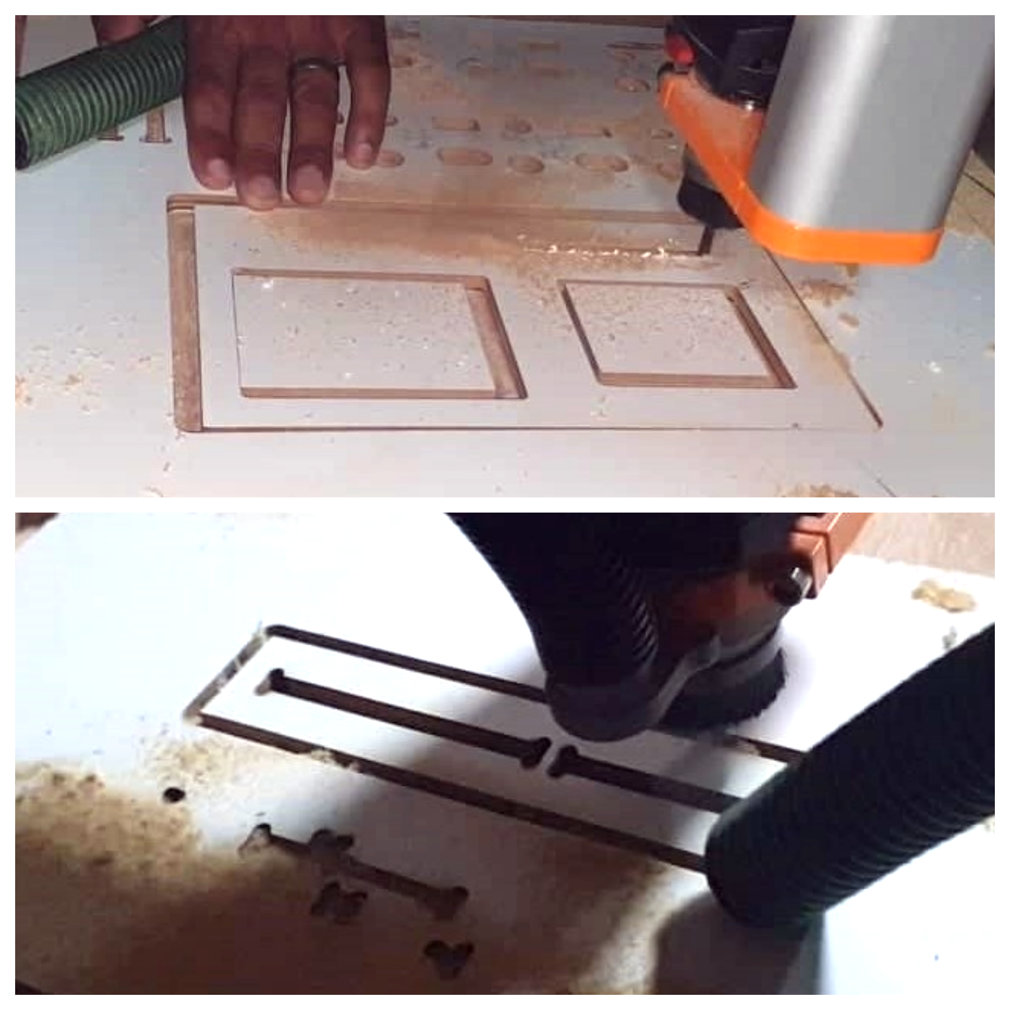
If you see below these are a few tests we made using the shopbot. On the table is the Aspire parameters we used for creating out spb file.
Test 1 Shopbot 8mm plywood
| SHOPBOT CNC | Selected |
|---|---|
| Cut Depth | 10 |
| Spindle | 2600 |
| Feed Rate | 100 |
| Plunge Rate 30 | 2.0000 |
| Pass dept | 0.125 |
| Passes | 4 |
Test 2 Shopbot mdf
| SHOPBOT CNC | Selected |
|---|---|
| Cut Depth | 11.2 |
| Spindle | 12000 |
| Feed Rate | 125 |
| Plunge Rate | 30 |
| Pass dept | 0.125 |
| Passes | 4 |
| Stepcraft D840 | Selected |
|---|---|
| Tool Dia | 6 |
| Target Dept | -9 |
| Outside Cut | |
| Saftey height | 15 |
| Step down | 3 |
| Feed Rate | 1500 |
| Plunge Rate 1500 | 500 |
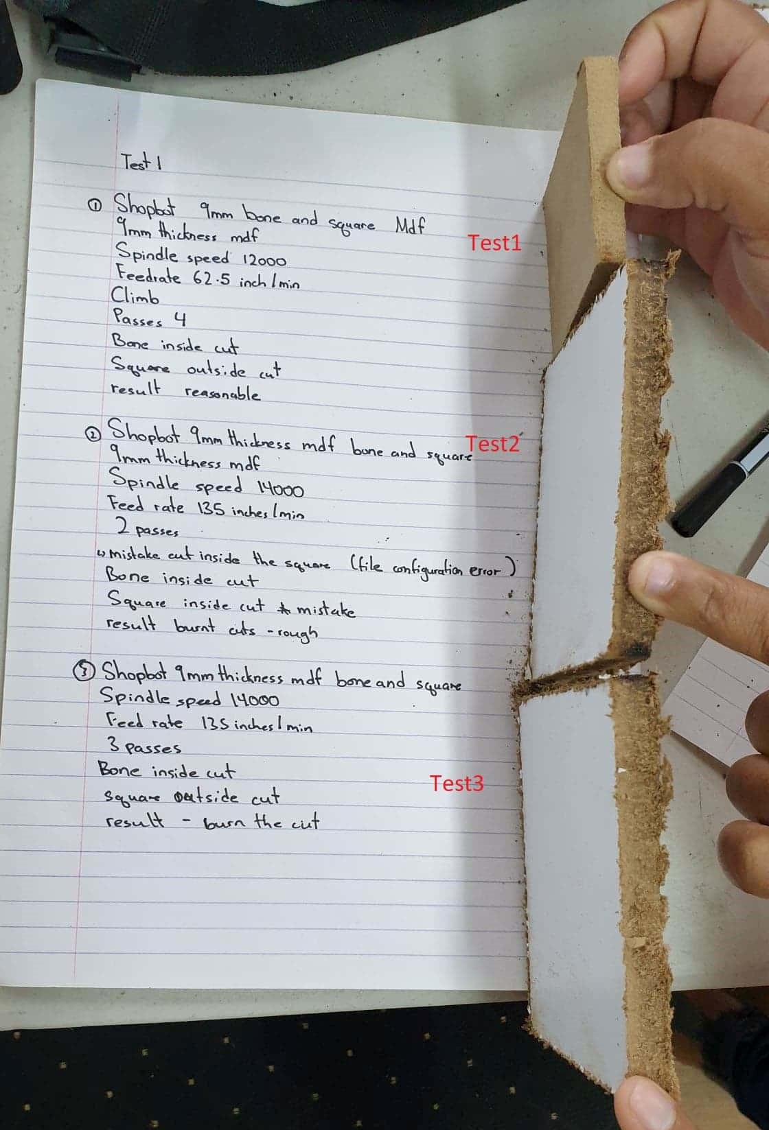
| Shopbot Day 2 | Test1 |
|---|---|
| Plywood | 9mm |
| Spindle Speed | 12000 |
| Feed Rate | 62.5 |
| Flute | 1 straight |
| Passes | 4 |
| Climb | |
| Bone inside | Square Outside |
Result: Average
| Shopbot | Test 2 |
|---|---|
| Mdf | 9mm |
| Spindle Speed | 14000 |
| Feed Rate | 135 |
| Flute | 1 straight |
| Passes | 2 |
| Climb | |
| Bone inside | Square Inside X mistake |
Result: Burn through the cuts and rough edges
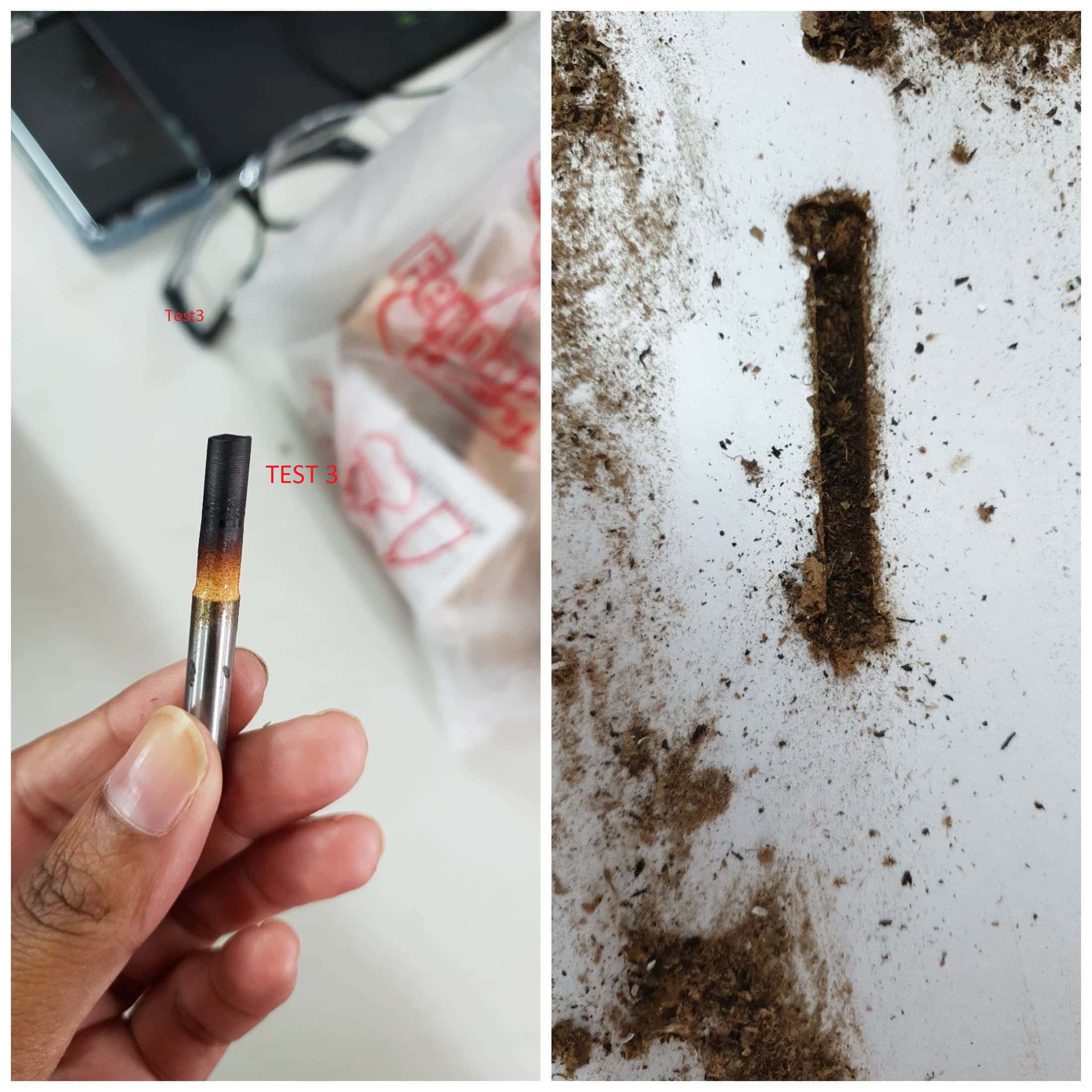
| Shopbot | Test 3 |
|---|---|
| Mdf | 9mm |
| Spindle Speed | 14000 |
| Feed Rate | 135 in/min |
| Flute | 1 straight |
| Passes | 3 |
| Climb | |
| Bone inside | Square outside cut |
Result: Burn through the cuts
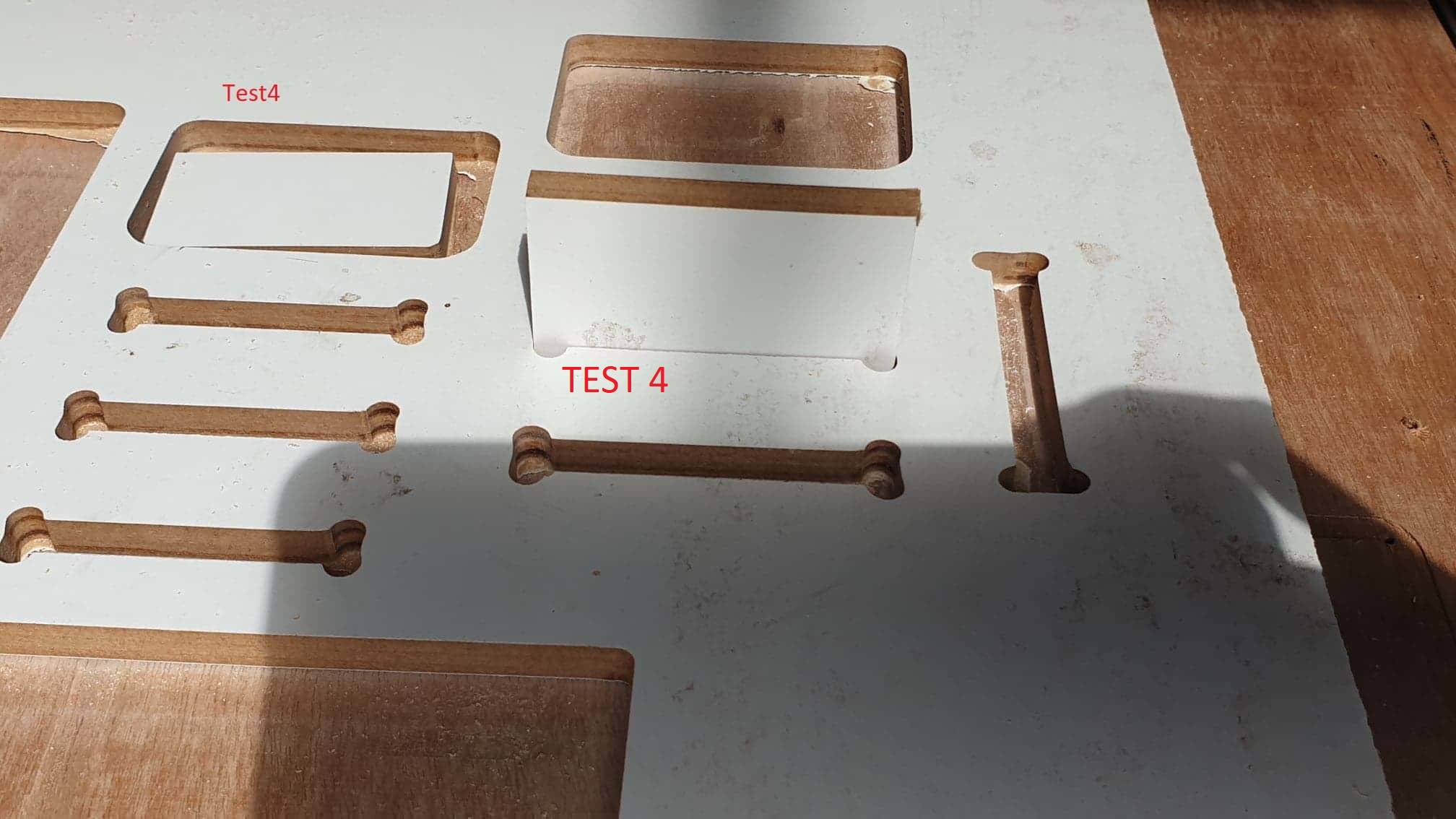
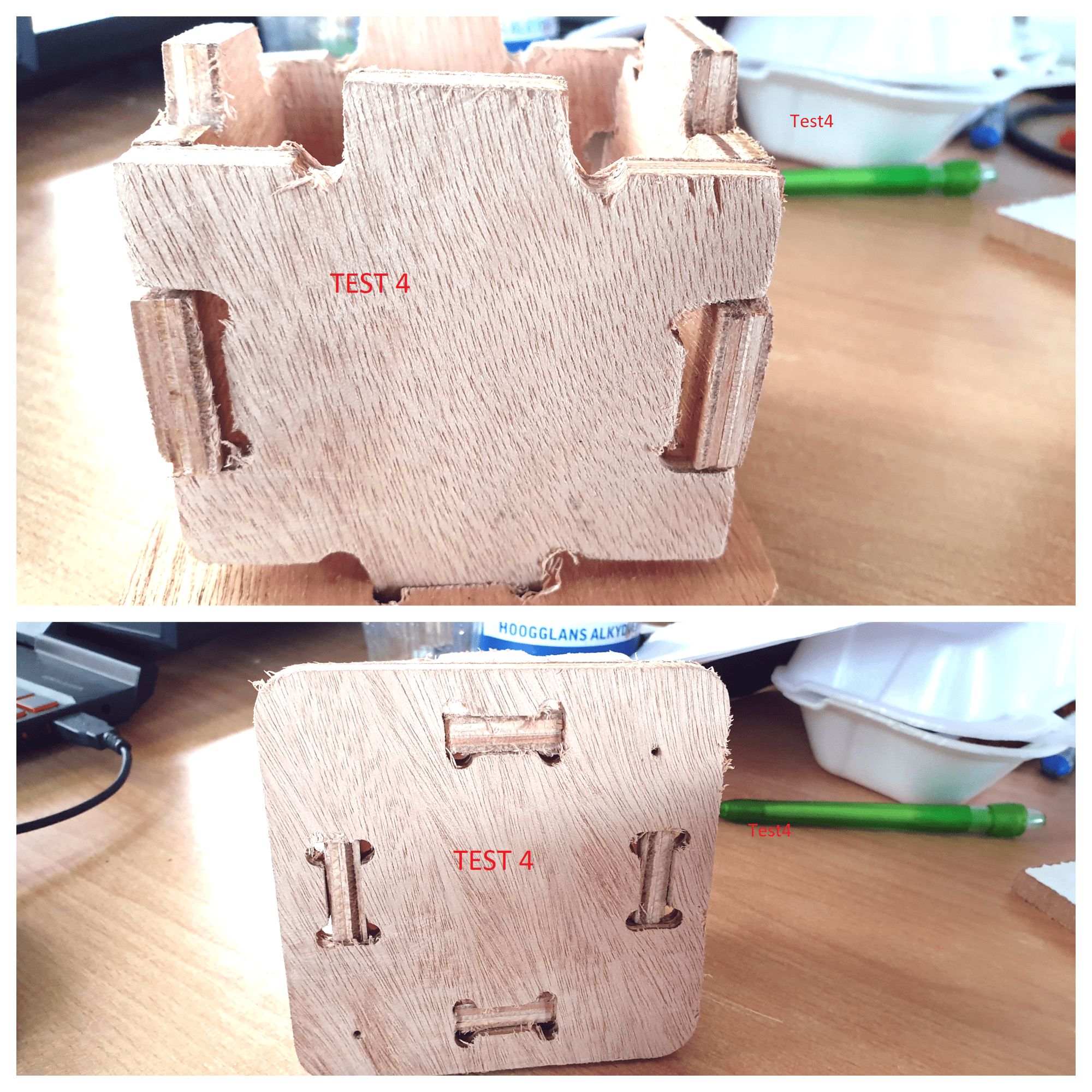
| Shopbot | Test4 |
|---|---|
| Mdf | 9mm |
| Spindle Speed | 12000 |
| Feed Rate | 62.5 in/min |
| Flute | 1 straight |
| Passes | 3 |
| Climb | |
| Bone inside | Square outside cut |
Result: Bit was no longer good it burnt out.
Stepcraft D840
| Stepcraft D840 | Test5 |
|---|---|
| Mdf | 8.5mm |
| Spindle Speed | 9000 |
| Feed Rate | 150 in gcode overrided in uccnc 70% in/min |
| Flute | 3 straight |
| Passes | 2 |
| Bone inside | Square outside cut |
Our material was 8.5mm mdf so we designed our test bone to be the width of 9mm and the factor which we adjust was to scale the selected pieces the square and bone by a factor of 1.1706 to adjust for the difference which the stepcraft was giving which was 17% difference from the design and the actual cut. For the end result the width of the bone became 10.53 for the width of 9 mm in the design and 8.5 mm material thickness.


 note: make sure to select the correct shopbot from the dropdown menu mine is shopbot inches