Assignment: Group: Test the design rules for your printer(s) Individual: a) Design and 3D print an object (small, few cm) that could not be made subtractively. 3D scan an object (and optionally print it)
Learning outcomes: Identify the advantages and limitations of 3D printing and scanning technology. Apply design methods and production processes to show your understanding.
Assessment: Have you:
a)Described what you learned by testing the 3D printers (group)
b) Shown how you designed and made your object and explained why it could not be made subtractively
c)Scanned an object, Outlined problems and how you fixed them
d)Included your design files and ‘hero shot’ photos of the scan and the final object
Group work
We have linked our group assignment external you can view it here
Characterize the design rules for your 3D design and Print production process
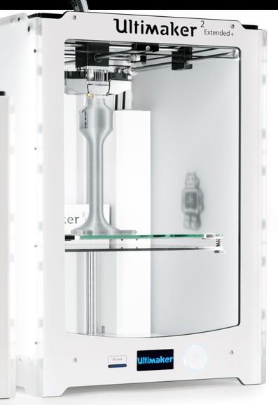
For our weekly assessment for the 3d design and print we used the printer available to us at Kazlab in called Ultimaker 2 extended + . It consisted of
An SD card, glue stick, grease, hex wrenches and a USB cable
Swappable 0.25, 0.4, 0.6 and 0.8 mm nozzles
A 0.75 kg spool of Ultimaker Silver PLA
A calibration card to level the build plate
The material which we used was easy fill pla color silver, 2.85mm and which needs 180 - 220 degress celcius to heat up
Before we started using the Ultimaker 2 extended + for printing we had to put the temperature to 220 degrees
The software which the 3d printer uses is called Cura you can downlod it here.
Cura accepts svg format and converts svg into gcode.
In cura you have the option to change parameters such as material type, nozzel, print speed, infill, wether to generate support or not and wether to add plate adition or not. Cura also tells you how long it will take for you to print your piece and how much material it will take. You can then save your gcode file either as a file or directly into your drive or sd card.
Test Piece
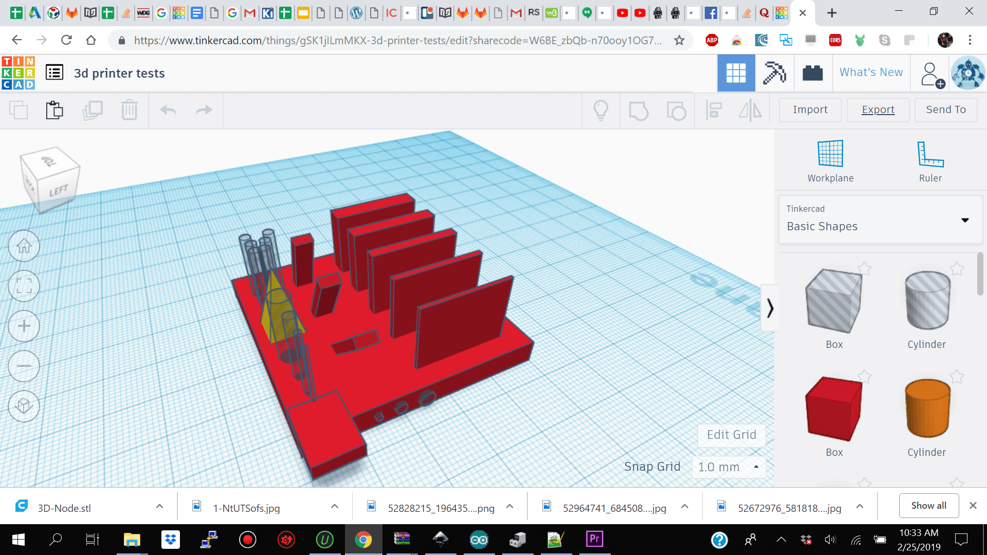
For testing the design rules for our printer we made this piece using tinkercad where we had
Walls of different thicknesses (from 0,5 mm to 4 mm)
Round holes with different diameters (from 1 mm to 3 mm)
Holes separated by different length spaces (0,1 mm to 2 mm).
Inclined and overhanging parts to test possible angles.
Pointy structure to test material bonding.
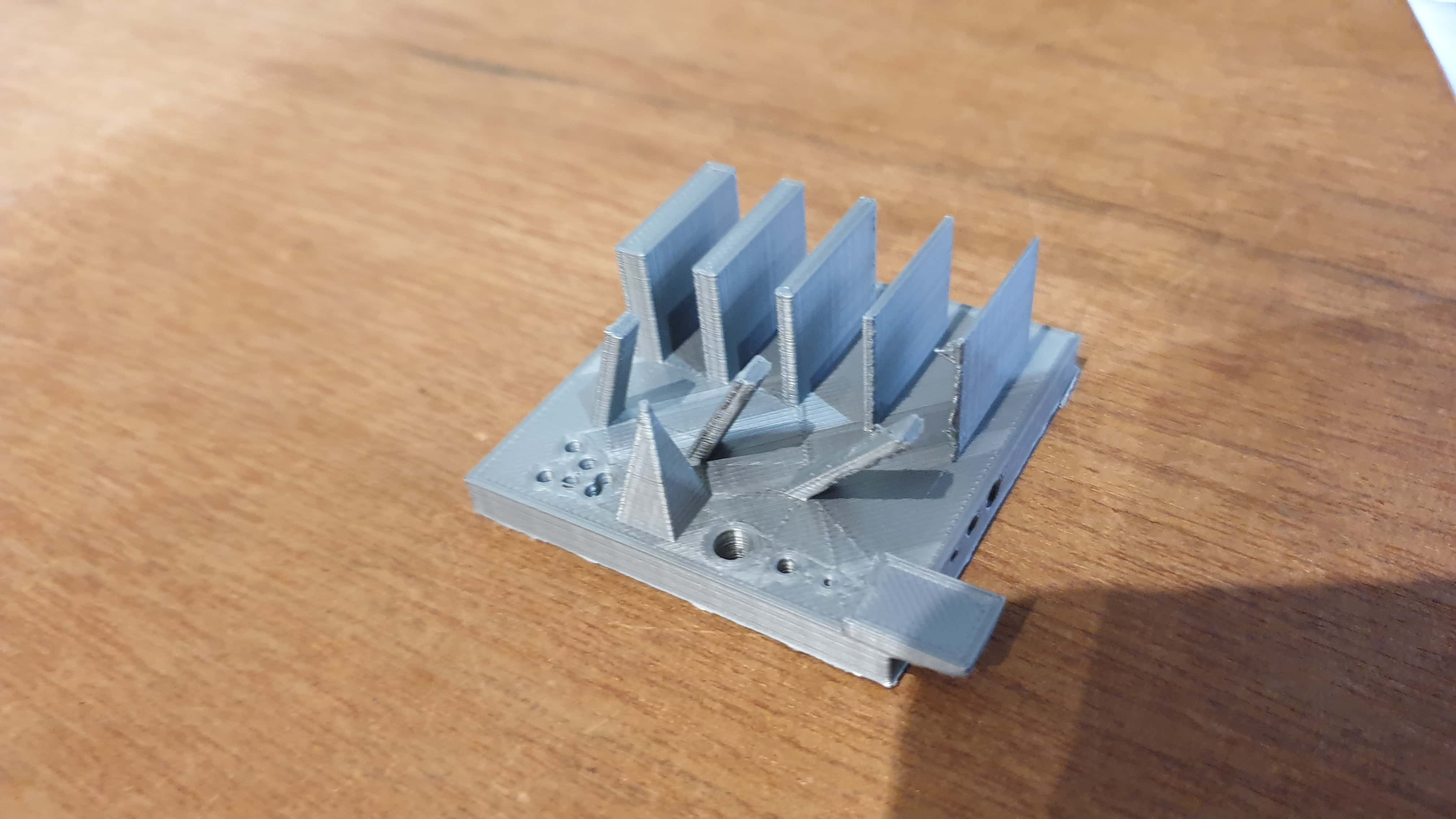
When the piece came out it came out pretty clean we did not have to clean pla off of it
The vertical holes of 1mm 2 mm and 3 mm diameter were good
The overhanging part did not collapse, but there were pla residue left from the support .
The vertical holes with separation of 0 mm, 1 mm and 2 mm were good.
The walls came out fine. The 1 mm thick wall is acceptable. The 0,5 mm printed well but is too weak.
The inclined parts were very good. The steepest one (45°) did not collapse.
Summary
Design my model using tinkercad and export as stl
Import design into cura and add parameter
Material Pla
Nozzle to 4mm
Print speed 0.15
Infill 20%.
scale x y z as prefered
Uplaod to sd card place into Ultimaker
Select and Fix Pla
Navigate to file
Start
3d Scan myself using 3d sense tool and software export stl file
Import to Cura
Repeat above procedure
3D Design
3D design
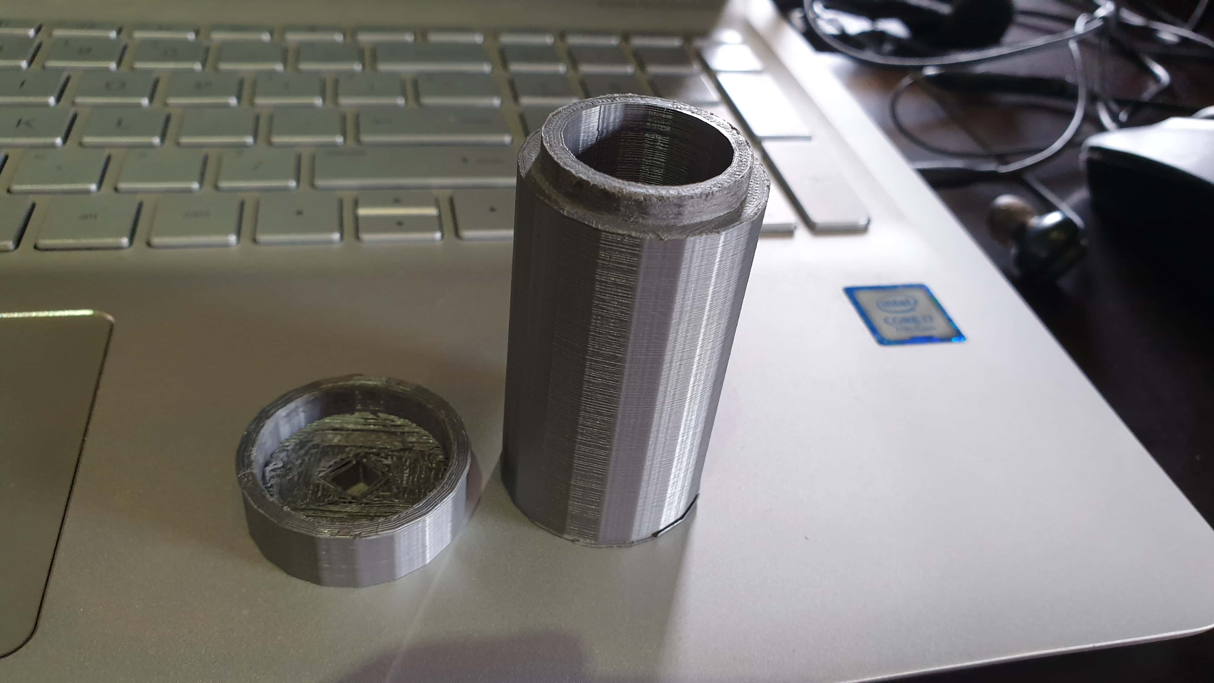
For this week assesment our objectvie was to make something non substractive using the 3d printer so I decided to make a test sample of my final project sensor node (base and cap) enclosure with some squares in it.I wanted to make a test sample of my enclosure because I wanted to test how it will fit together with the pressfit cap and to get a feel of how it would look in reality.
As I understood it, a design that can not be made subtractively, means creating a design that you cannot easily mill on a CNC mill or similar.In our lab we were using the 3axis stepcraft cnc machine so that was my reference point.So I decided to make a cylinder enclosure and added a square for the push button and a square in the cover for the led and one at the bottom on the base for the sensor input. I think this design cannot be made substractively because the cnc would not be able to reach the depth to cut a cylinder out of the wood and the mill would not reach to cut the squares on the wall of the cylinder.Also if I did not specifically design the dogbones for the squares the cnc would make round corners on the square holes instead of actual squares.
The tool which I used to 3d model my enclosure was tinkercad. I had tried tinkercad before when I started off researching and testing out cad tools and I realized that it was quite a simple tool to use. I eventually left it behind because I saw that it was limited to a only a few functions. I then went ahead and used fusion 360 to design my final project but then after using fusion 360 I also found it too tedious to use if I would want to make something small. So for this weeks assessment since we were going to make something small and not too complex i decided to go back to tinkercad and make my enclosure there. I decided to make a sample of what my final project sensor enclosure will look like so I can get an idea of how the press fit cap would fit and the dimension if it will be too small for fitting my battery.
When starting using tinkercad to design my enclosure the first thing which I did was to make sure I don't make something too big because I knew the 3d printers take time to print stuff. After confirming with my local instructor I decided to go with
30mm x 50mm for the base and 30 x 10 mm for the cap.
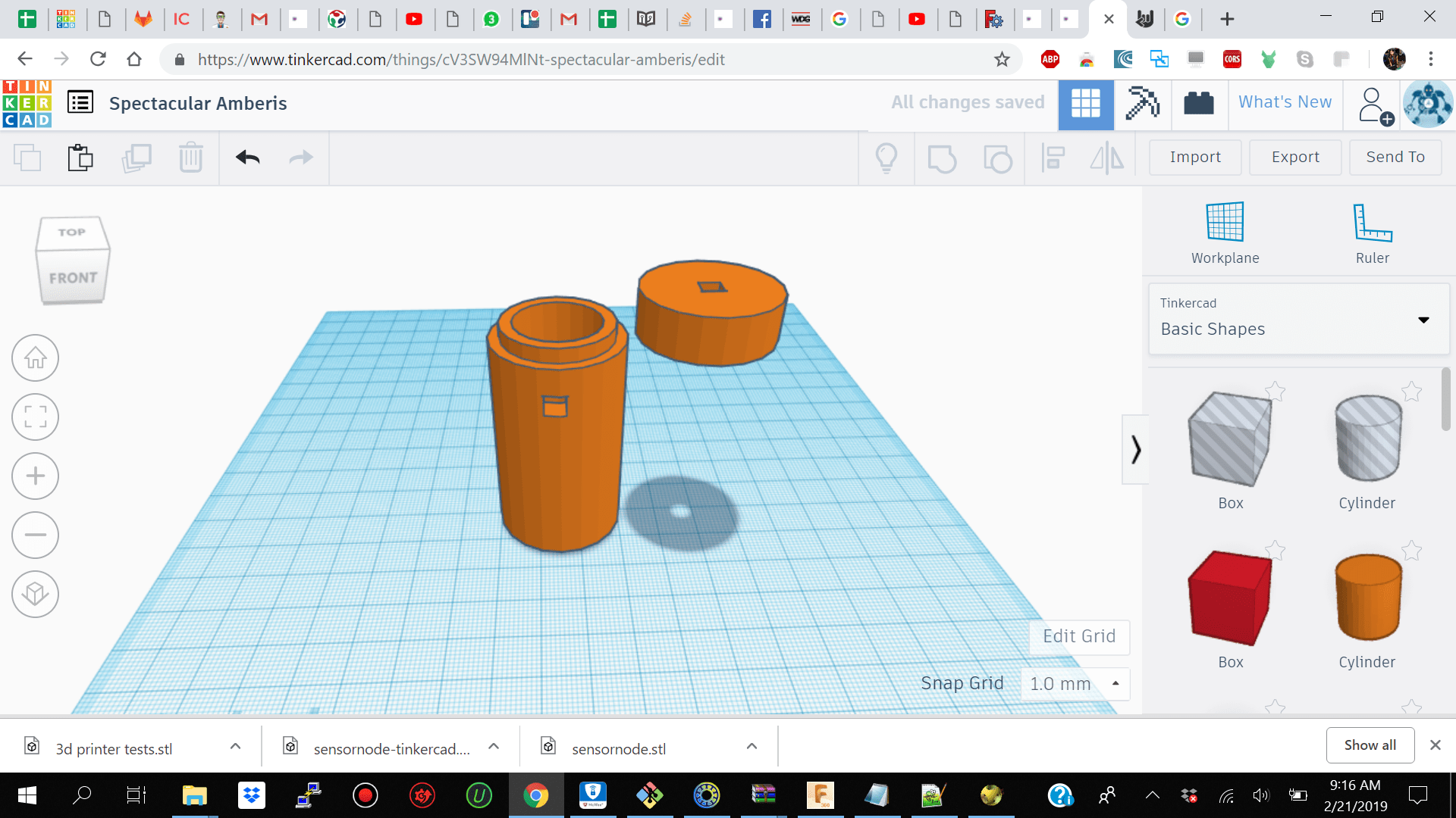
I then used cylinders and squares in tinkercad to make my enclosure. I first made a cylinder
30mmx50mm
then I align and group another cylinder parameter hole into that one so I can make a hollow out of my container on the top half of my base unit. I then added two holes of different sizes of squares for the bottom and side of my base for the sensor input and power button and on top of my cap for the led.
After finishing with my Node I exported the base as one svg file and the cap as another svg file. It was then ready to be imported into Cura for be converted into g code
When using Cura I imported my 3d design in stl format
material which was Pla
Nozzle to 4mm
Print speed to be on 0.15
Infill 20%.
I did not select generate support because I did not want the printer to fill in support where I wanted the holes in my design.I then selected Build plate adhesion and selected prepare file to see how long it will take for my file to print and how much material it will take.
I then selected save to external driver so that it can be saved onto my sd card as gcode making it ready to be used by Ultimaker
I then went over to the Ultimaker and inserted by sd card. I did not have to preload the filament because it was already there for when we were making the group test for the 3d printer. I then selected print and navigated to my gcode file from the menu.After selecting my file I had to then had to wait for the plate to heat up.
After the plate has been heated up the printer would deposit a small amount of filament on the left corner of the plate so that you can check if it has been headed well and is without bubbles then it was ready to print my design. My design after being prepared was estimated to take about 1 hour and 25 min and it actually took 1 hour and 20 min so I was very surprised at how accurate the estimation was.
You can view below a little time lapse of my base design
3d Print
For 3d printing both my non subtractive piece and 3d scan object we used the Ultimaker 2+ Extender. The first thing I had to do was to converd my stl file into gcode using Cura.I then uploaded my file onto the Sd card and inserted it into the Ultimaker.I then selected print and navigated to my file and pressed print.note: I had to add paper glue to the plate before pressing start.
The Ultimater then took about 2 min to heat up then after the plate was heater to 220 degrees it release a deposite of pla at the side of the plate for me to check if the pla is smooth or heated enough.
If you are satisfied by how smooth the pla in about 5 seconds the Ultimaker will start printing your piece.
My 30mm x 50 mm piece took 1 hour and 15 min to print
. After my piece was finished I took a small spachula and flip it off the palte.
The second part of our assesment was to 3d scan something and print it.I decided to 3d scan something big which was myself. The Scanner which we used was the 3D Sense Scanner
The first thing which I did was to download the 3d sense software note: the software version depends on if you have a older or newer version of the sense device. When I initially tried the 3d sesne device the software which I downloaded did not work with my sense device because the sense device was an older version.
We then went ahead and got ourselves ready for the scanning. For the sense to make a good scan we had to make sure there were not too much light in the backgroud which would disture the scan.So we then closed all the doors.I then make a circular parimiter free and put a rotating chair in the middle and sat on it so that there were enoguh space around me for my classmate to go around and make the scan.
We initially did not want to have to tape the device to our laptop and rotate around the object so we tried rotating the chair instead with the person and keeping the scanner still but that did not work because the sense also needed to detect the background instead of stitching pictrues together.
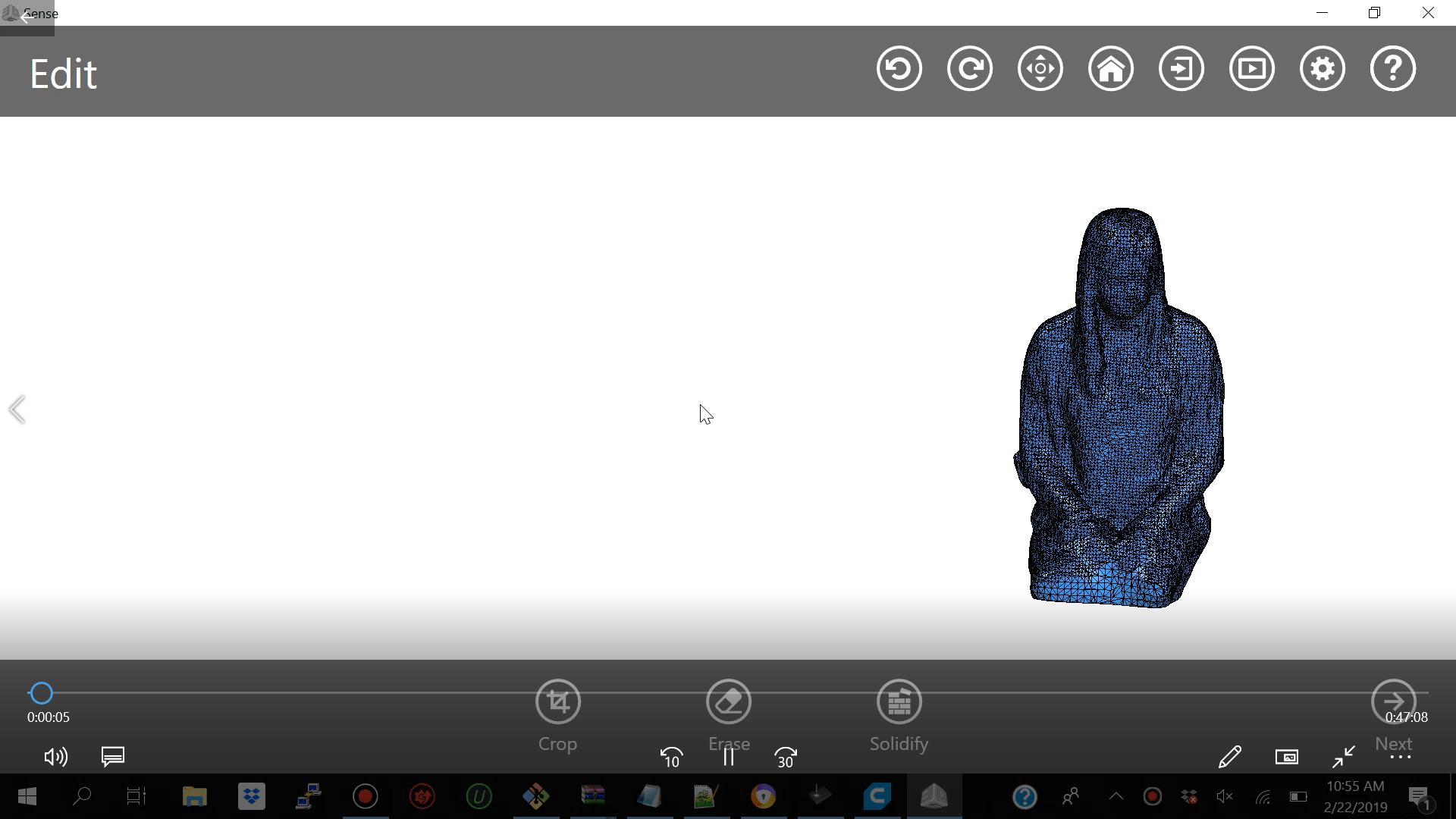
We then taped the device to my laptop and selected upper body my classmate then walked slowly around me to get the 3d scan of my upper body but the issue which we were getting was constantly loosing track of object so we decided to select full body and just physically scan my upper body
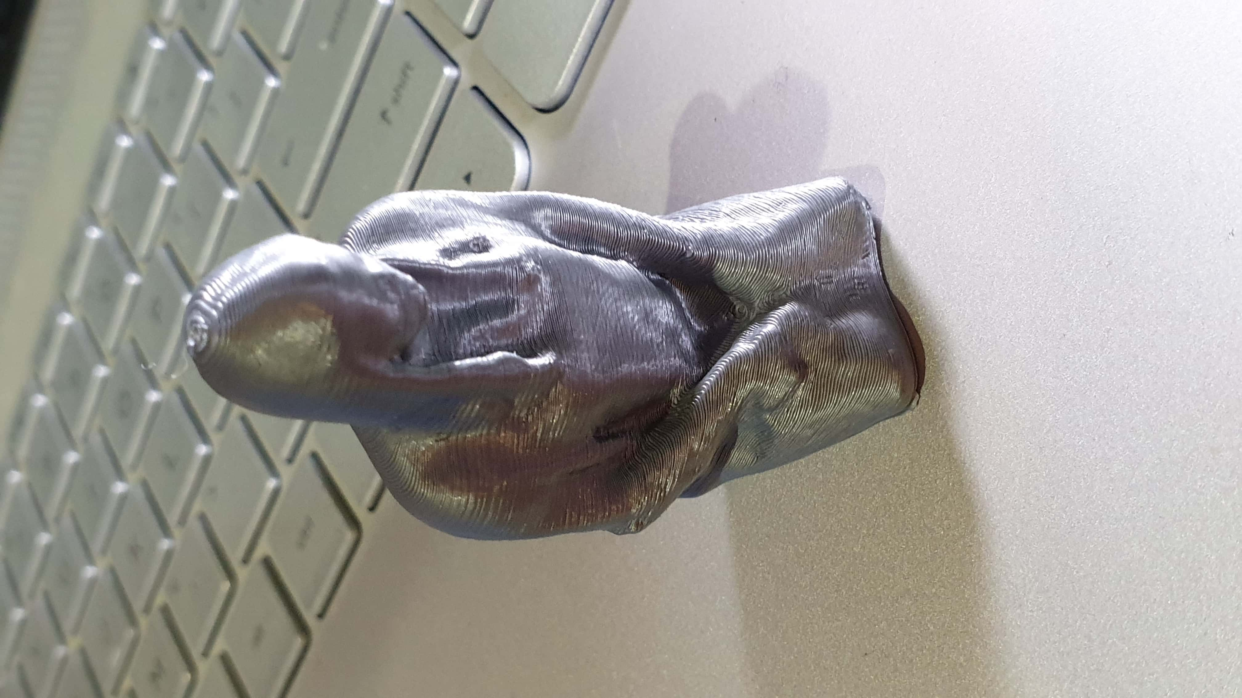
With that option selecting full body instead upper body we were loosing on the details and focusing more on the general figure so that came out pretty good but the only downside is when my print came out I did not have a face
After I was finished with my scanning I then downloaed my file as stl and imported it into Cura. I then scaled the image and position it to x y z 0 and it was ready to be printed.My piece took 1 hour to print on 5 percent scale.
When designing and object using the 3d printer takes time. My small 30mmx50mm part took 1 hour and 20 min.
Make sure you use a Pla which is new and has not been exposed to humidity for best quality.
When using the 3d scanner tool do not try turning the object instead of you moving around the object to get the scan because you will end up seeing a zombie looking version of yourself if you are trying to scan yourself.
Make sure you have the proper software for your scanning tool because when I initially installed sense software my scanner tool was not compatible with the new version of the sense software.