Designing
Summary
- Architecture Expectation vs Reality
- Design Application Interphase Microcontroller Board / Final Project Test V1.0
- Creat New Project & Sketch KICAD
- Import Fab Library
- Import Components
- Connect Components
- Give Compoents correct name and value
- Annotate the design
- Assign Footprint to Symbols
- Generate Netlist
- Open Pcb New
- Read in Generate netlist
- In Pcb New Set Design Rules (Setup -Design Rules)
- Rearrange Components and Make Traces
- Place your Auxillary Axis
- Plot Layers
- Flatcam
- For the front cut I selected
- Tool dia / 0.2
- Passes /2
- Cut Z / -0.1
- Travel Z/2.5
- Feed Rate / 3.0
- Spindle speed 1000
- Edge Cut
- Tool dia /0.8
- Passes /1
- Cut Z /-1.5
- Travel Z/ 0.1
- Feed Rate /3.0
- Spindle speed 6000
- Multip dept checked
- Depth/Passes 0.5
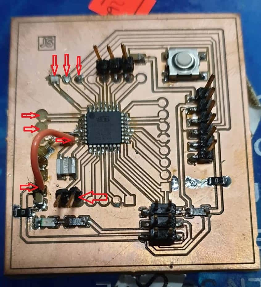
- Solder Atmega Microcontroller Board
- Pitfals
- Redesign Atmega Version 2.0
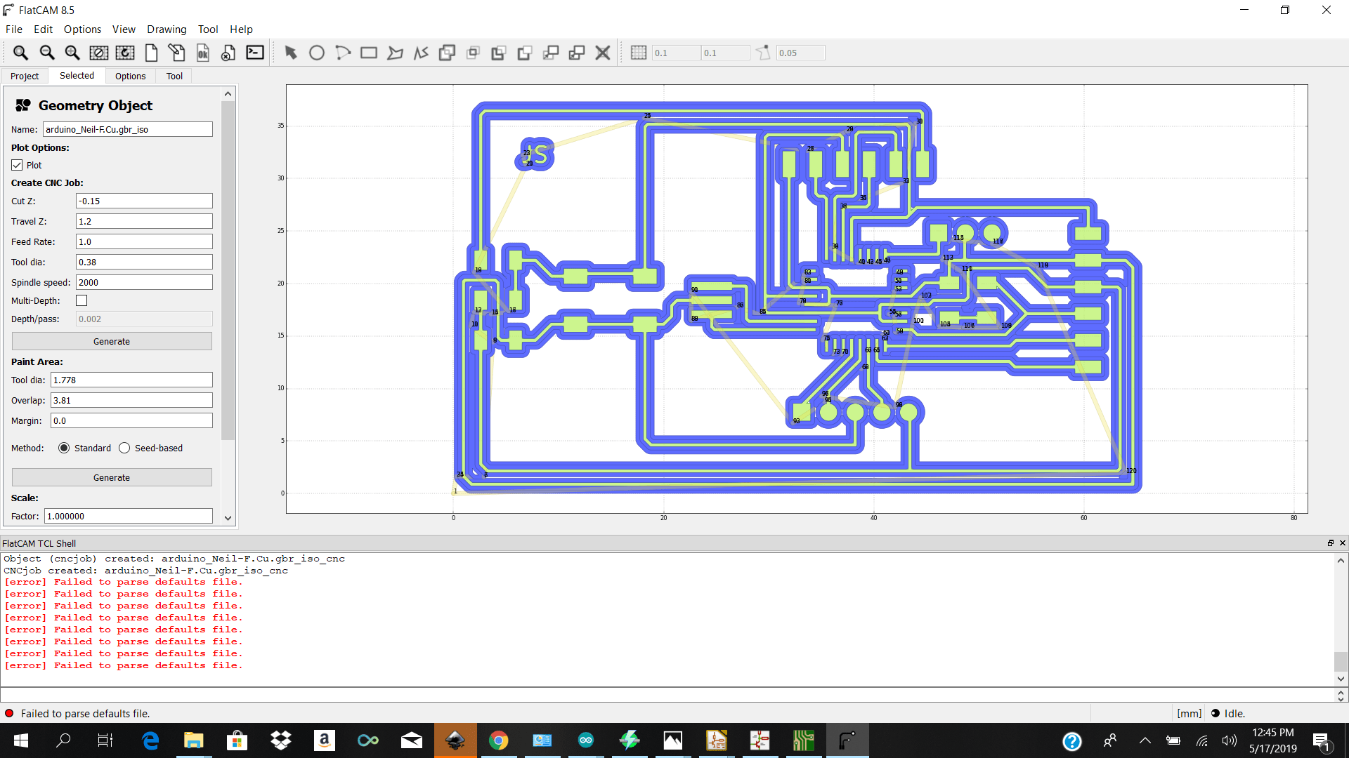
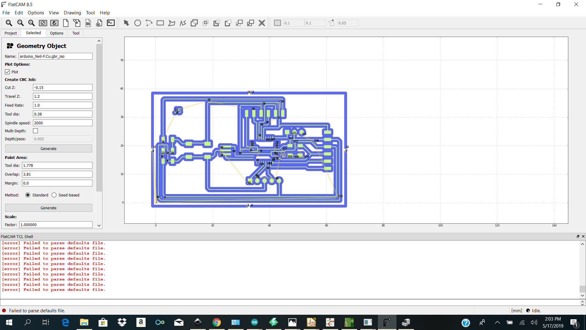
- For the front cut I selected
- Tool dia / 0.38
- Passes /2
- Cut Z / -0.15
- Travel Z/1.2
- Feed Rate / 1.0
- Spindle speed 2000
- Edge Cut
- Tool dia /0.8
- Passes /1
- Cut Z /-0.15
- Travel Z/ 1.2
- Feed Rate /1.0
- Spindle speed 2000
- Multip dept checked
- Depth/Passes 0.5
- Programming the Gui
- Programming the Controllers
Expectation vs Reality vs Conclusion
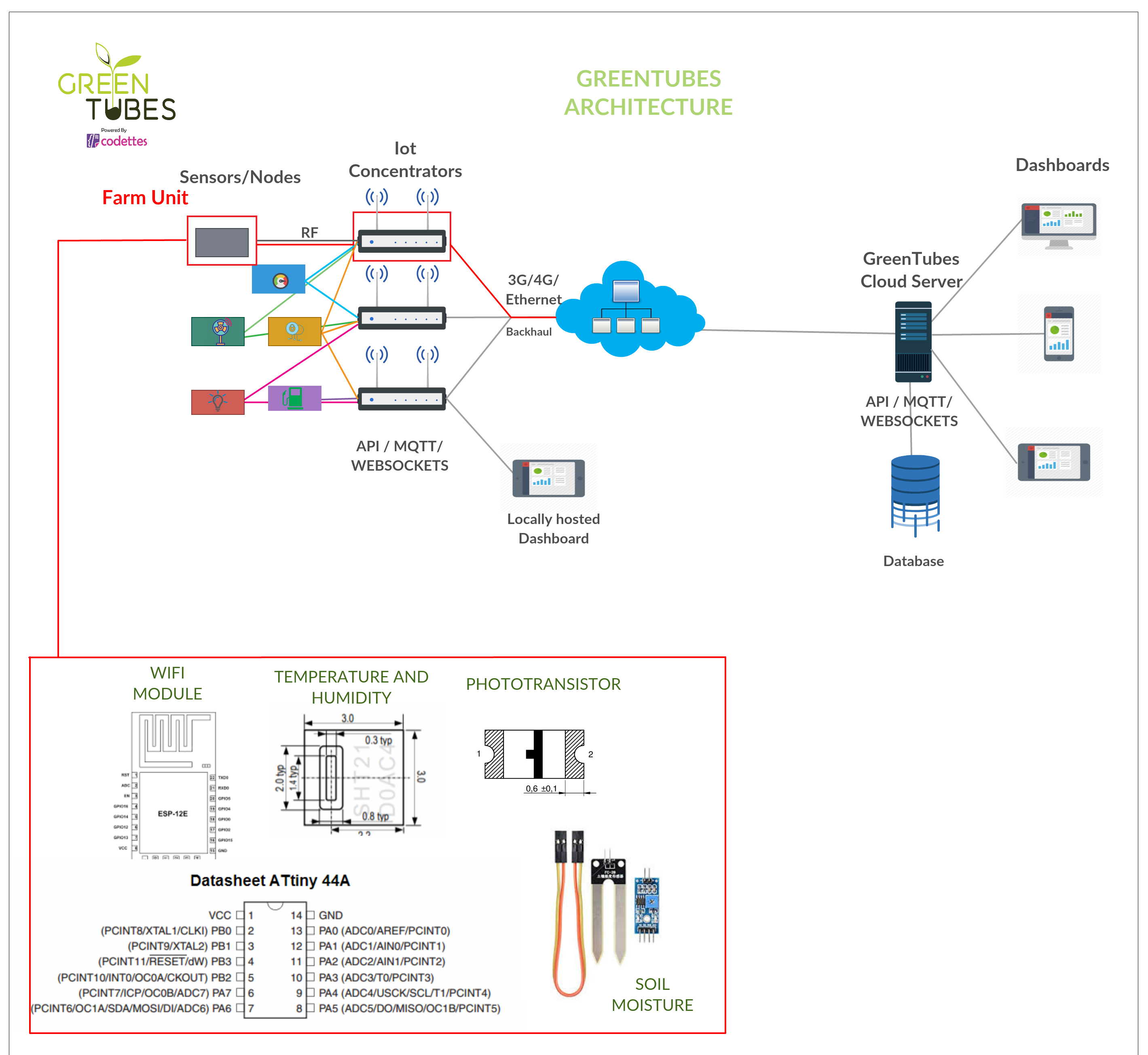
Initial Architecture
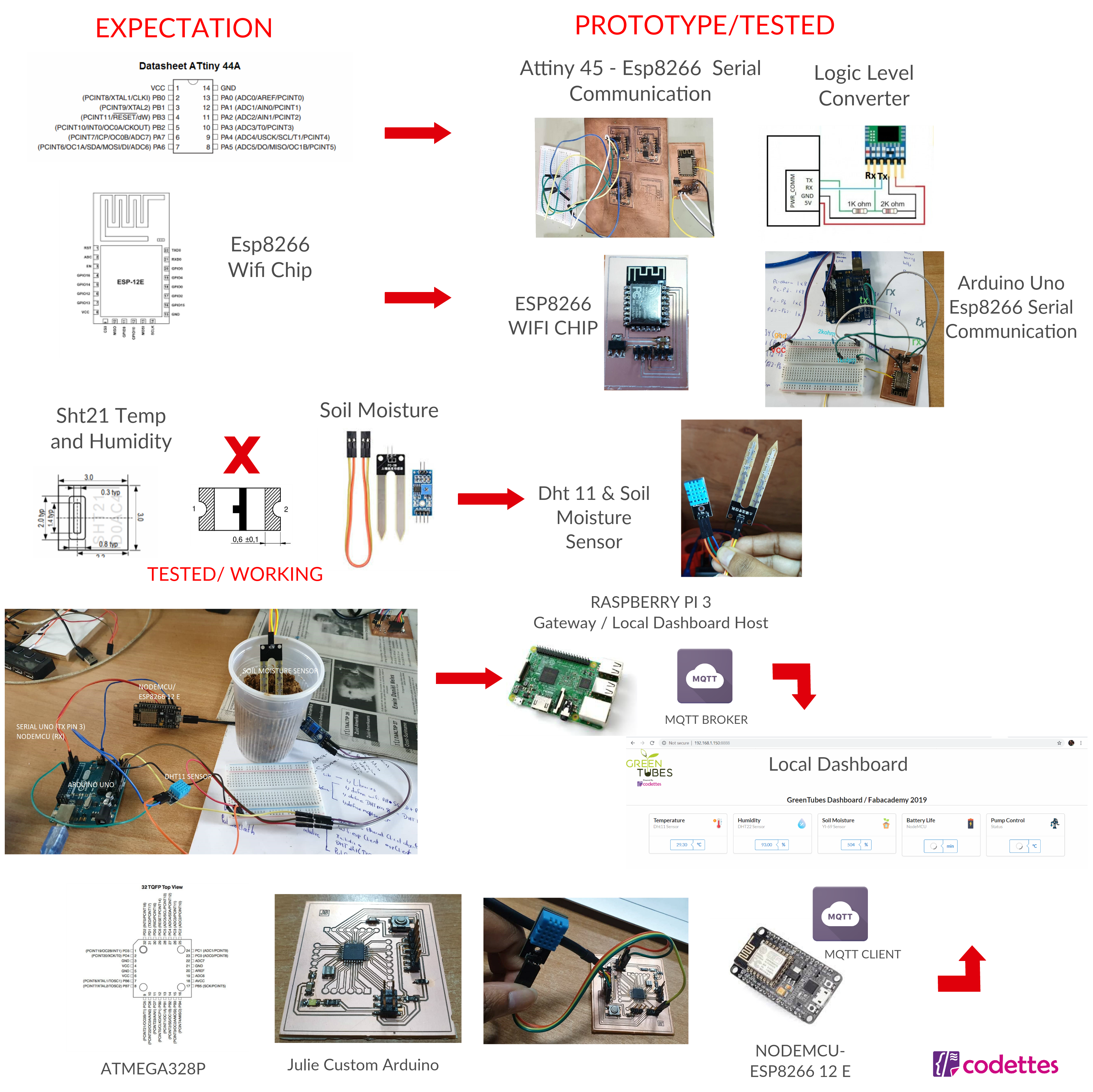
Current Architecture plus Testing
Designing
For Interface and Application Programming I decided to make a microcontroller board using the atmega328p microcontroller board because I wanted to combine this week with my final project.
My initial design was to use a attiny44a microcontroller but after doing some testing compiling the libraries for my sensors such as the dht etc was giving me too many errors compiling on the attiny series so I decided to save time and just use the atmega because I could test first compiling on my arduino uno and then upload the code to my board I designed myself.
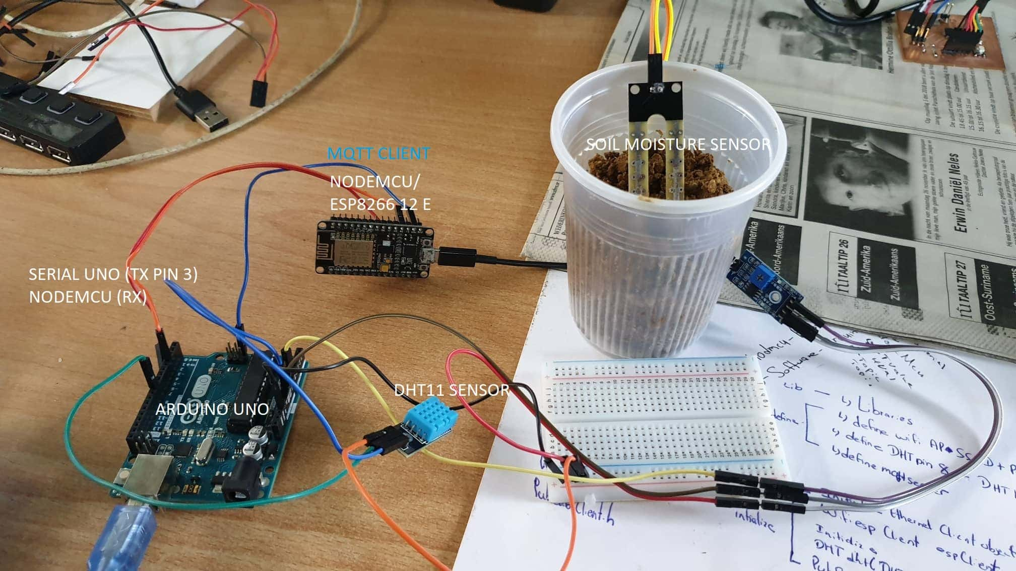
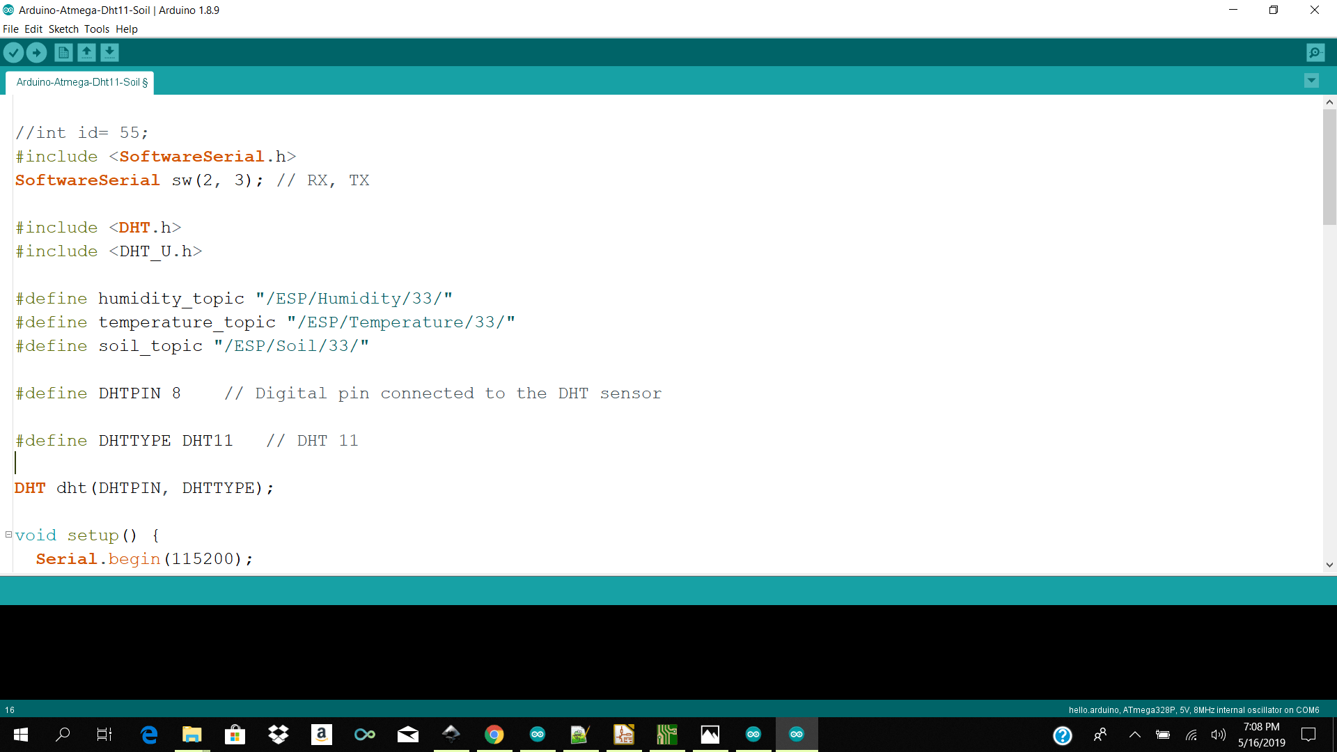
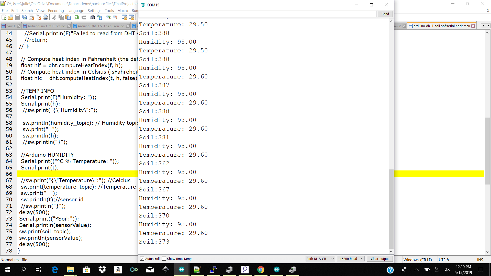
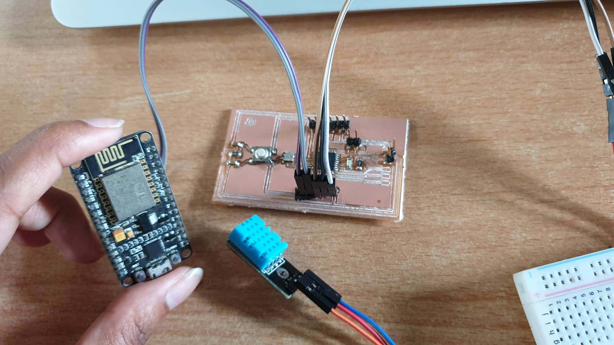
Before I started off designing and soldering my atmega I decided to used the arduino uno to test my temp humidity and soil reading send it to my nodemcu over serial and to see if the nodecu which is acting as my mqtt client connected to my localnetwork / connect to my mqtt broker on my rpi3 /received the data coming over serial and send my data to my rpi which is hosting my mqttbroker and relaying the data over websocket and showing it on the widgets on my dashboard.
I did my tests and it worked.
I started off by using niel's design of the atmega328p and test to see if that would work I took this image and remade it using kicad.
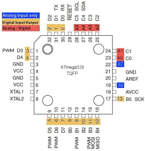
Atmega328p datasheet Component list
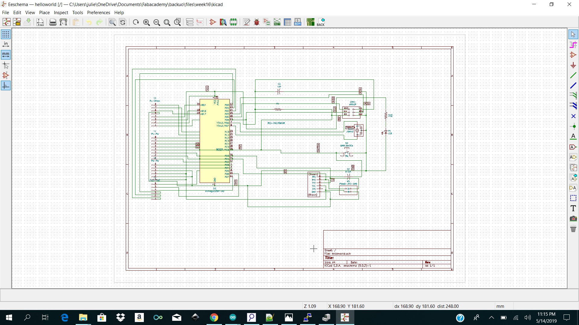
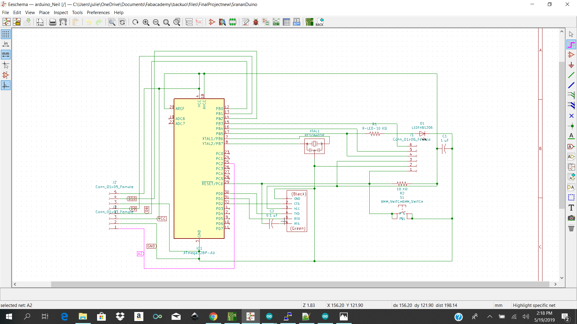
I then went ahead and started making my skematic in Kicad. I made a new project and started selecting my components from the fab library. After making my schematic in kicad I went ahead and anotate to check if I had my tags labeled correctly.
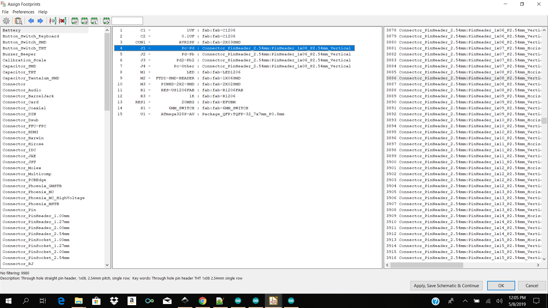
After that I went ahead and selected assign footprint to pcb and added my footprint. Most of my footprints were easily found but the only one which took me a while to find was the Connector_Pinheader_2.54mm:1x08_P2.54mm_Vertical
I then selected on Generate netlist and imported my netlist for Pcbnew.
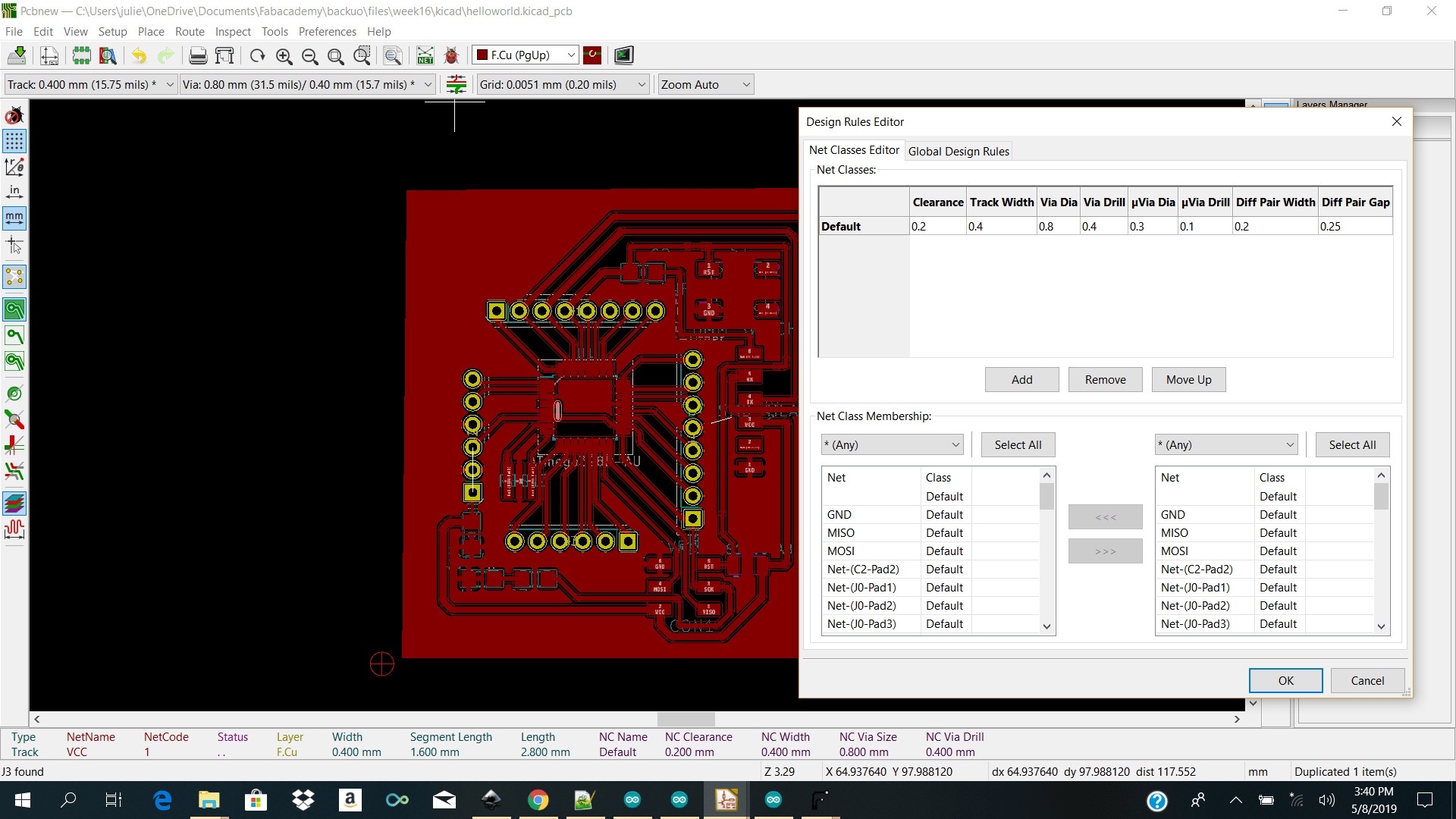
I then went ahead and choose my design rules from Setup → Design rules
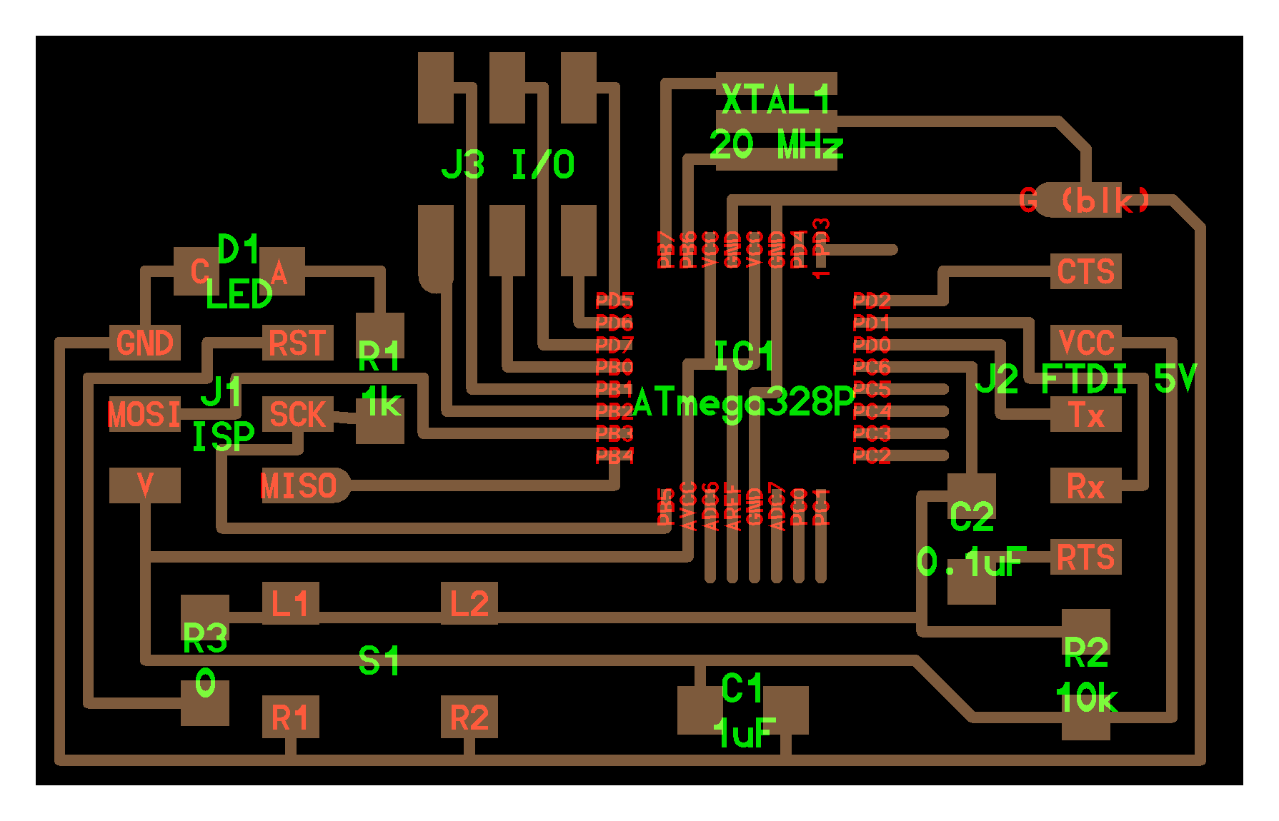
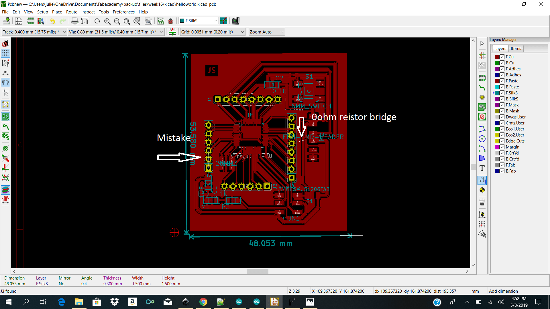
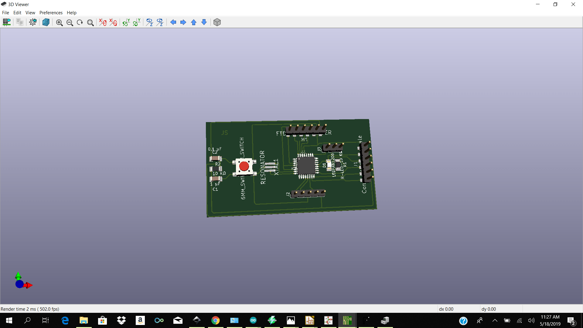
 I then went ahead and routed my board and also added a GND PLANE around my entire board.
Note: I made one mistakes I forgot to bridge my vcc to vcc and I could not find a way to get my gnd plane to leak into my layout to get to my ftdi gnd pin so I bridge it with a 0 ohm resistor.
I then went ahead and routed my board and also added a GND PLANE around my entire board.
Note: I made one mistakes I forgot to bridge my vcc to vcc and I could not find a way to get my gnd plane to leak into my layout to get to my ftdi gnd pin so I bridge it with a 0 ohm resistor.
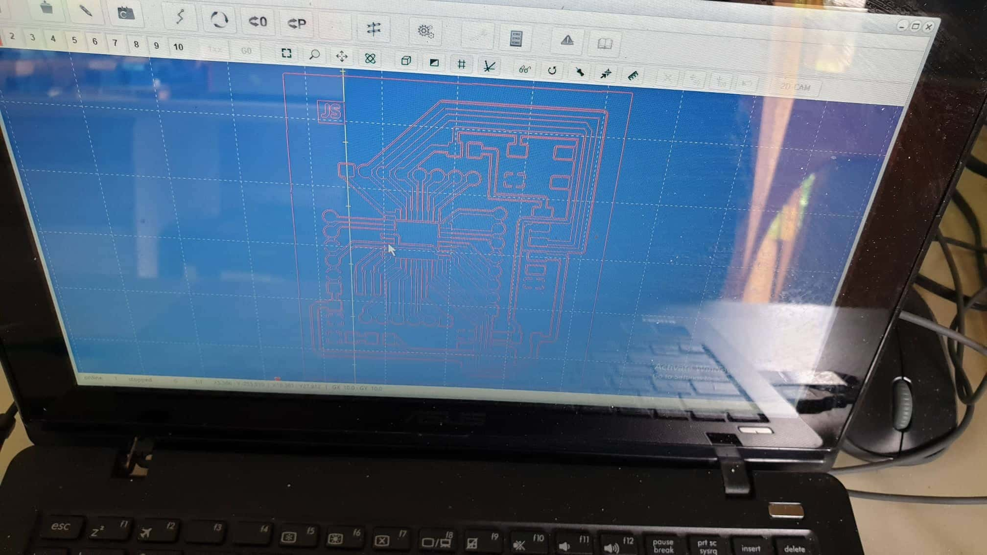
I then determined my auxillary origin using the place the auxiliary origin icon and went ahead and plot my layer. When plotting I checked off front . After generating my gerber files I then went ahead and open flatcam to add my parameters.
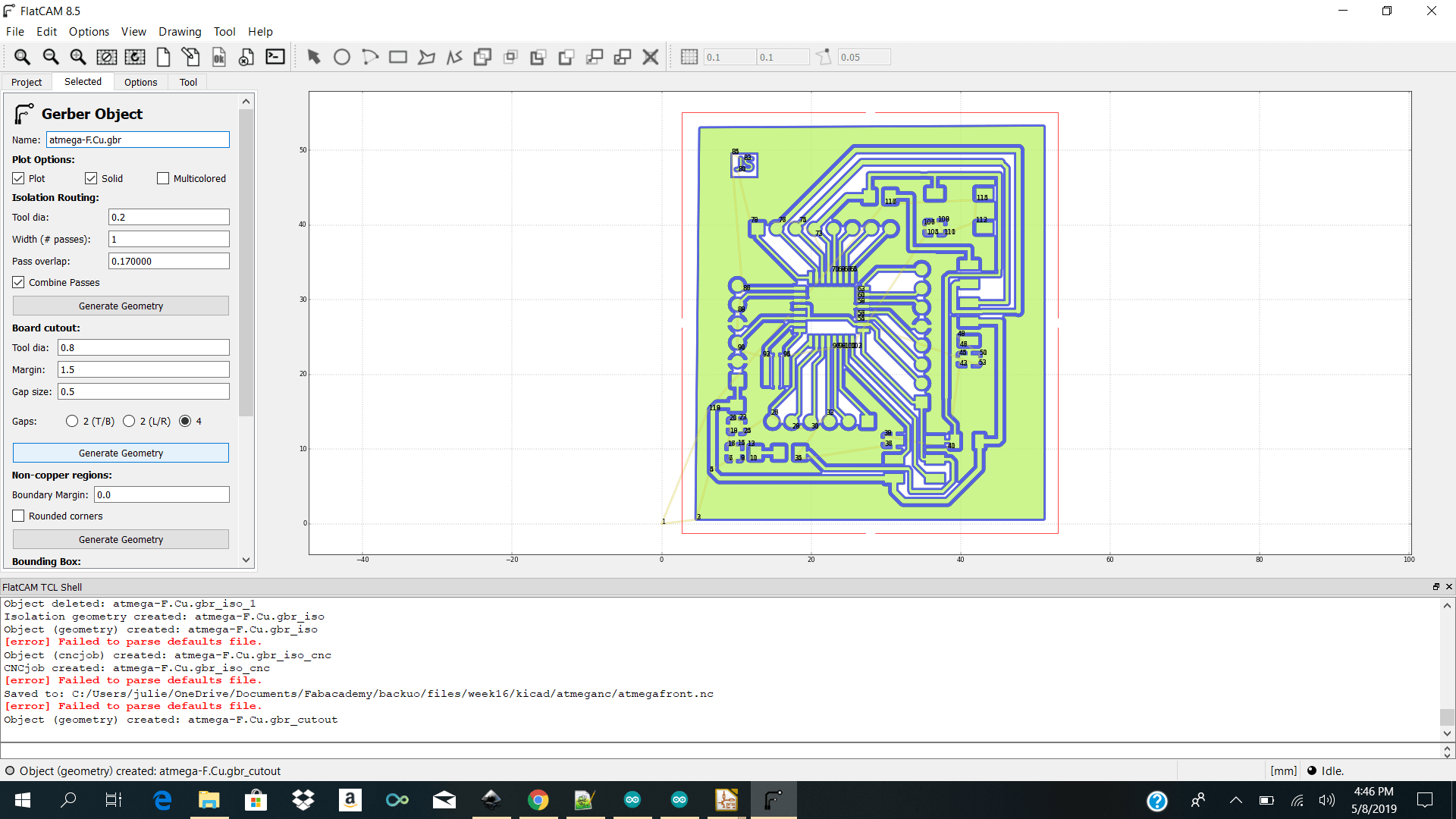 For the front cut I selected
Tool dia / 0.2
Passes /2
Cut Z / -0.1
Travel Z/2.5
Feed Rate / 3.0
Spindle speed 1000
Edge Cut
Tool dia /0.8
Passes /1
Cut Z /-1.5
Travel Z/ 0.1
Feed Rate /3.0
Spindle speed 6000
Multip dept checked
Depth/Passes 0.5
For the front cut I selected
Tool dia / 0.2
Passes /2
Cut Z / -0.1
Travel Z/2.5
Feed Rate / 3.0
Spindle speed 1000
Edge Cut
Tool dia /0.8
Passes /1
Cut Z /-1.5
Travel Z/ 0.1
Feed Rate /3.0
Spindle speed 6000
Multip dept checked
Depth/Passes 0.5
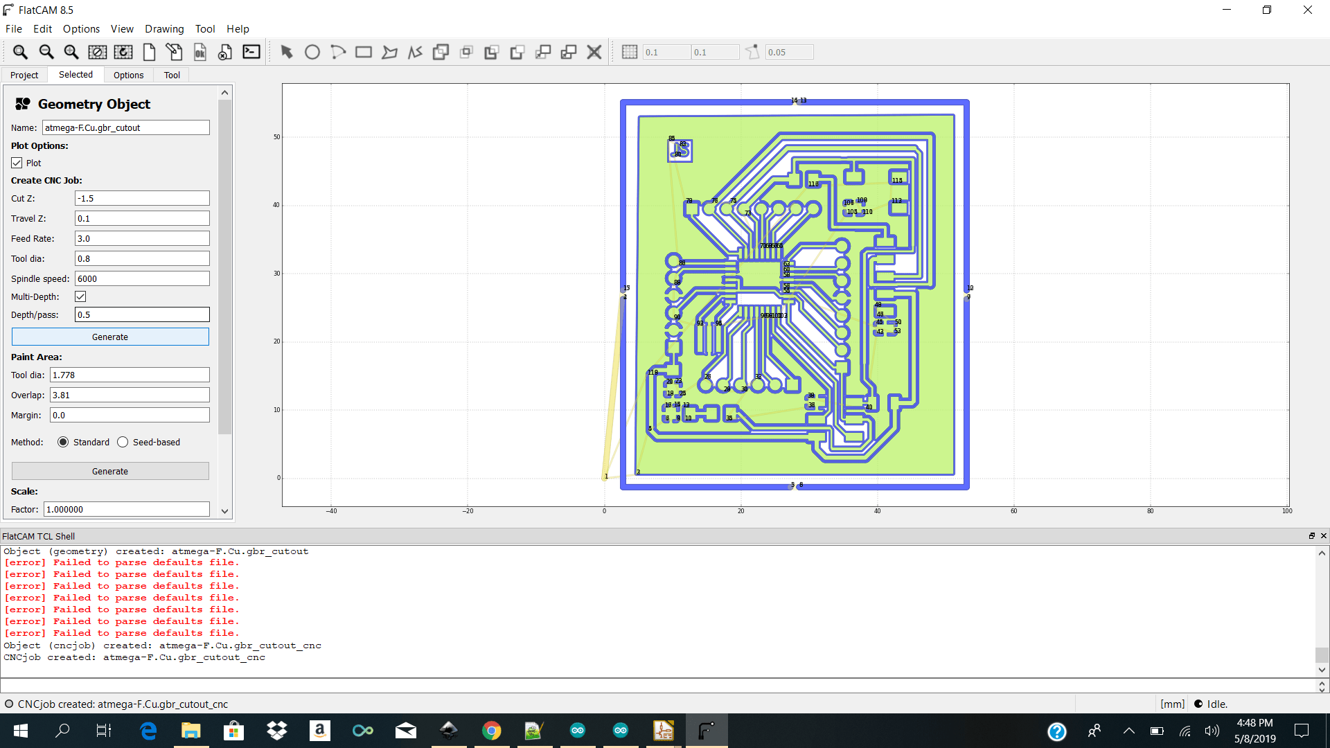 I then went ahead and generated my nc files for importing into winpc nc to control the stepcraft to cut the pcb.
Machining
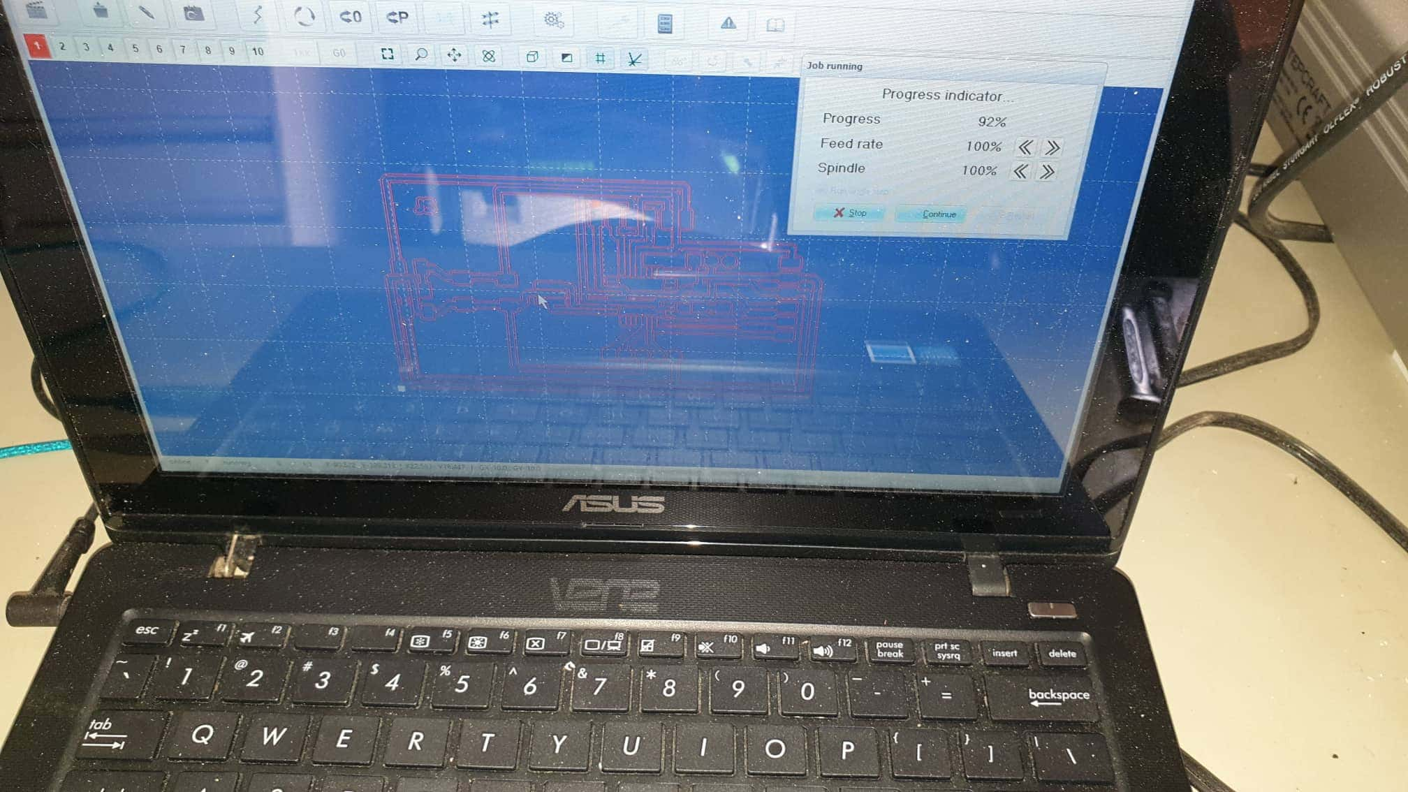
I then went and physically placed my copper plate onto the stepcraft base plate using double sided tape and imported my front cut.nc file into winpcnc. The parameters I had to keep in changer were add under
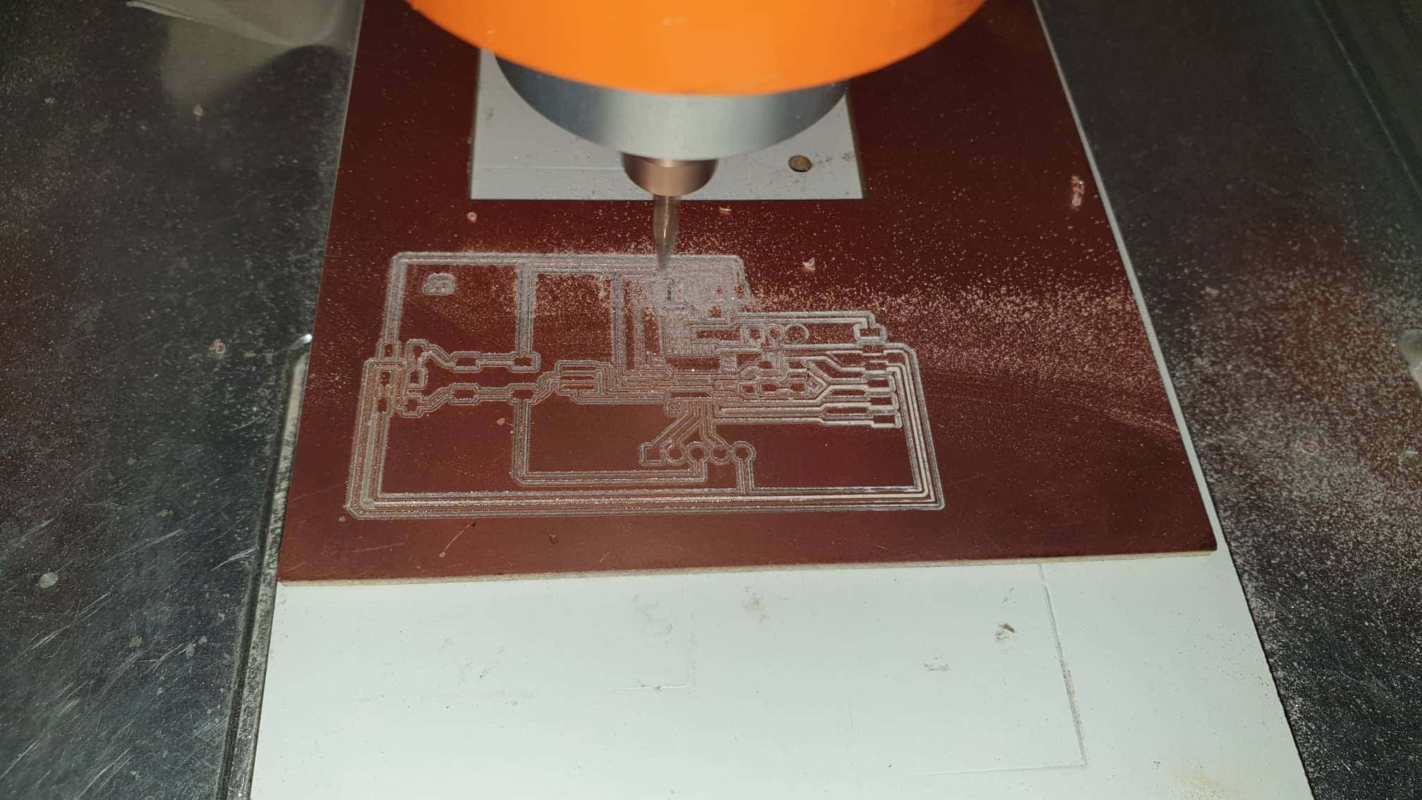
I then went ahead and jog the mill to my preferred x y and z positions. After I double checked that my x y and z positions were good I clicked on start and milled my board out.
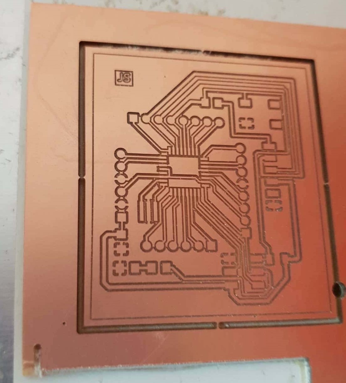
When my front cut was finished I did the same for my edge cut.I uploaded my edgecut.nc file then made my zero position was correct and press start.
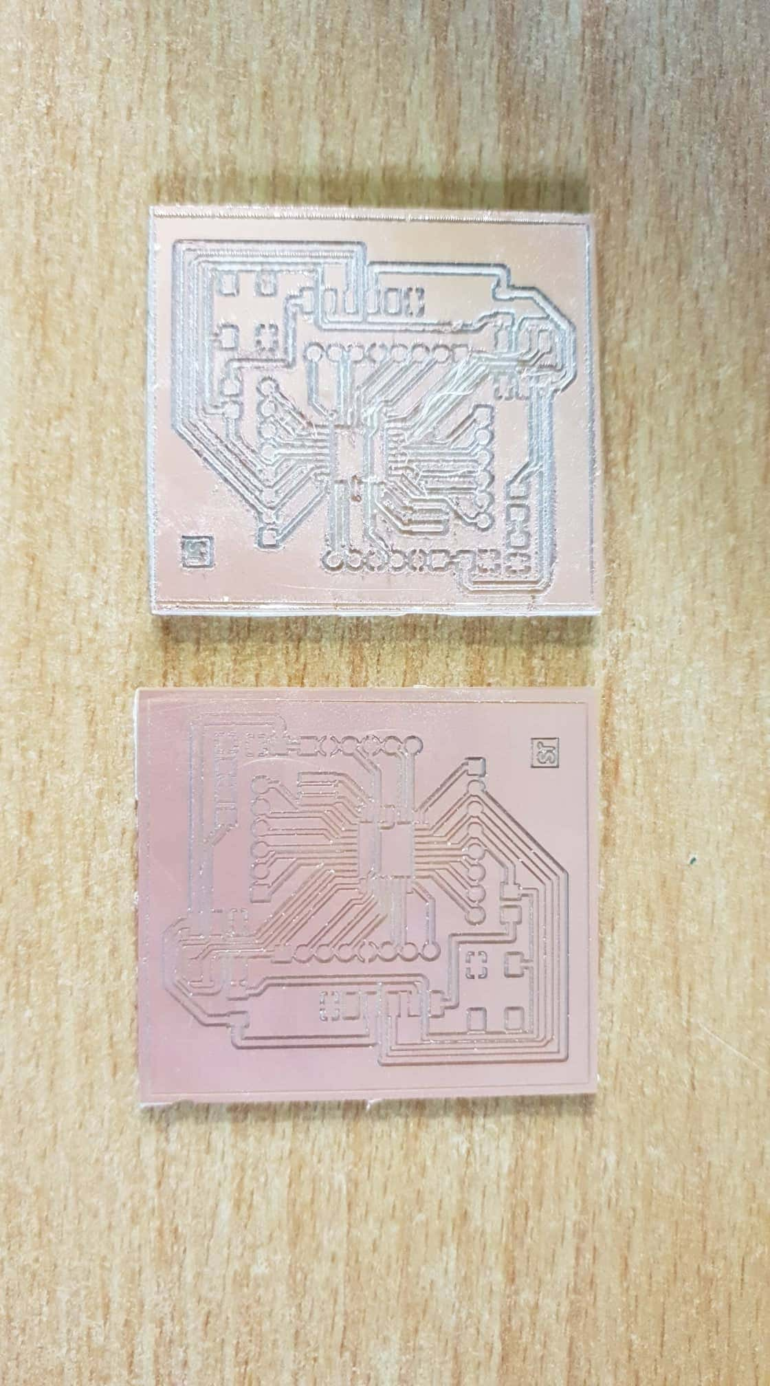
Some trials before I got it correct before and after the first one was I went too much down on the cutz the second was less and the third was the best.
Soldering
Soldering
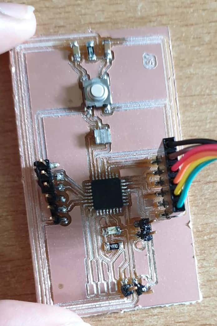
After I got my pcb milled I took the multimeter and checked my connections if all that needs to be connected is connected and all the does not need to be connected is not. I was so happy that all the connections were good. I then went ahead and gathered my smd component and soldered my board.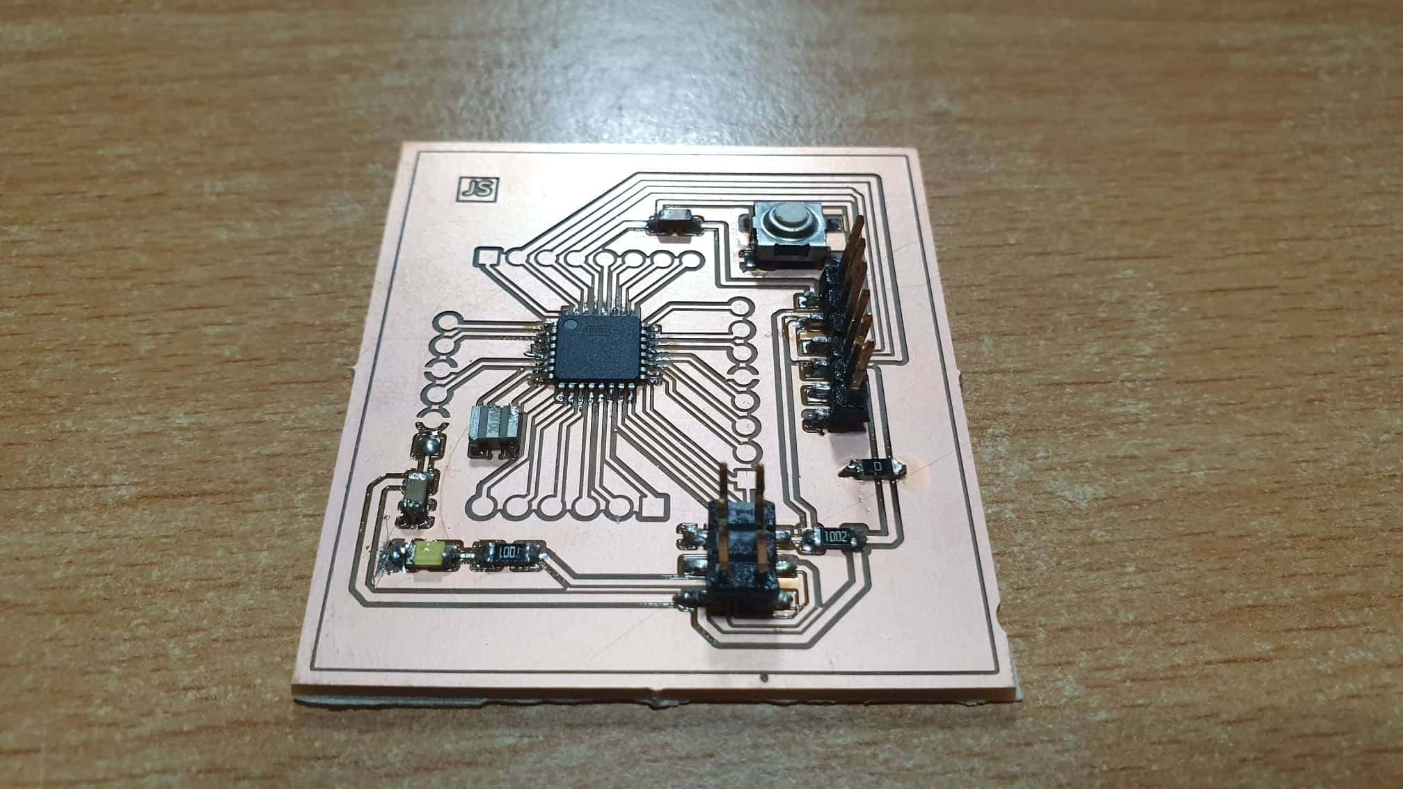
Programming
For programming I had 3 devices to program
Programming the Gui / Dashboard / Nodejs / Mqtt / Websockets/ Html /Css
GATEWAY ON RPI3
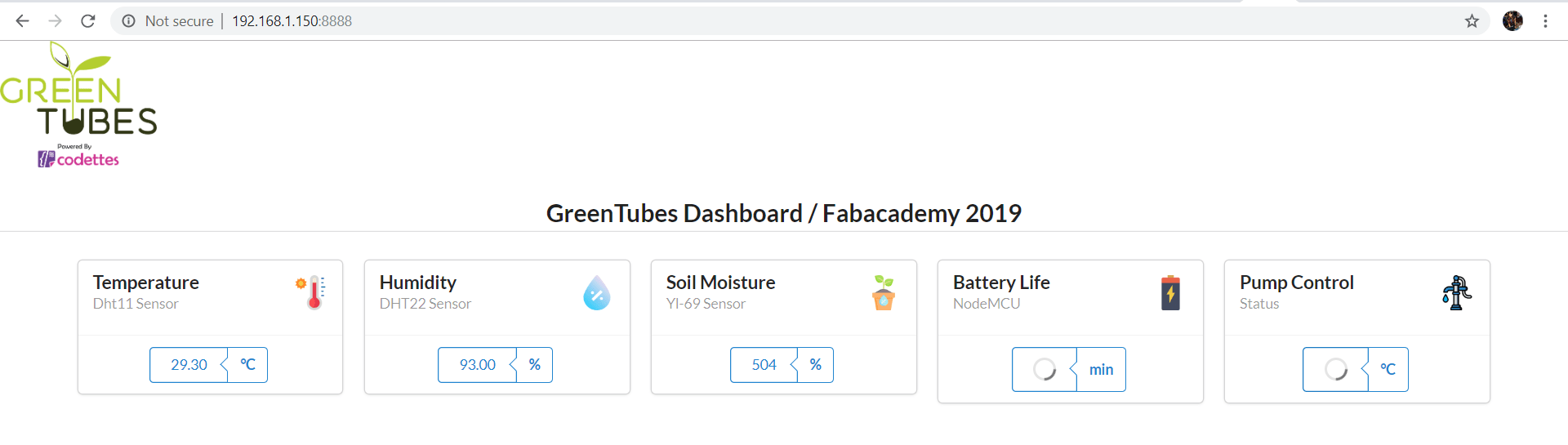
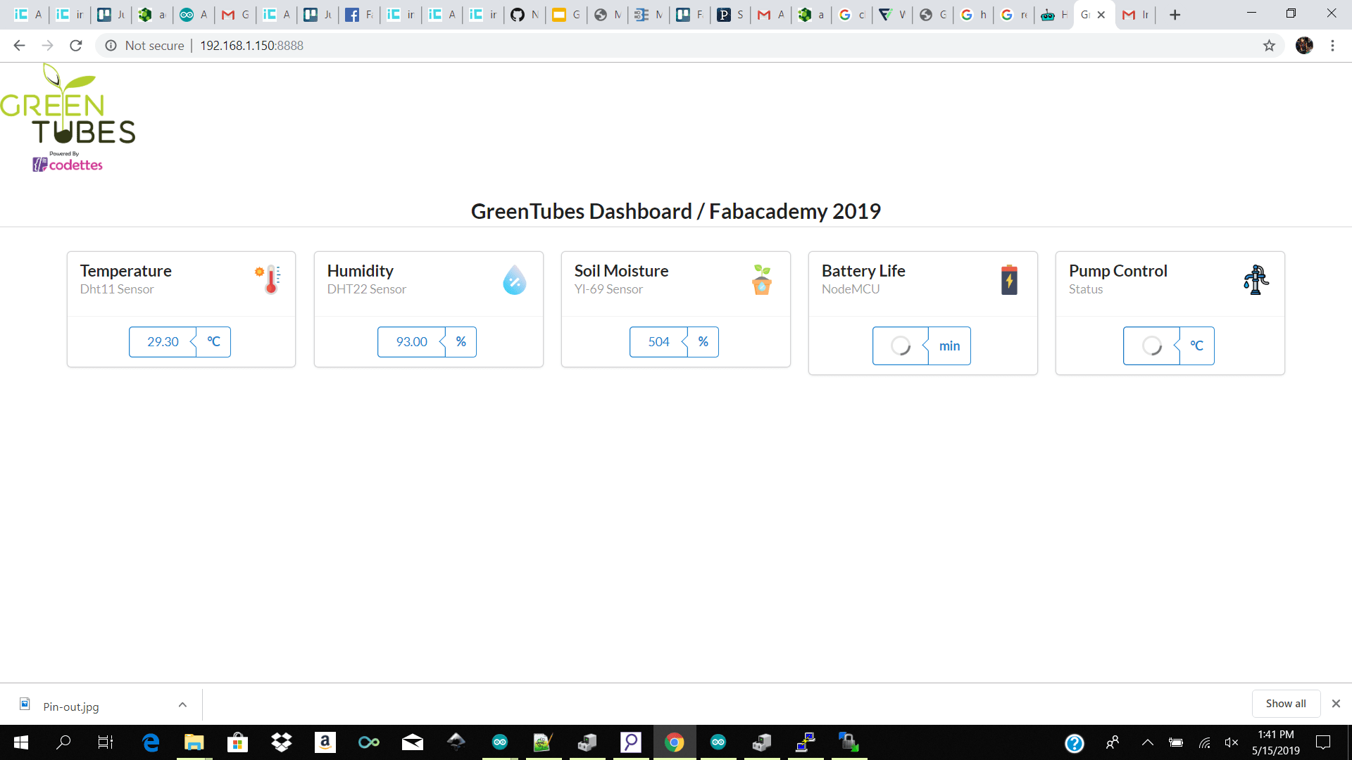
For my first test I had nodejs (express socket.io )and mosquitto installed on my gateway (Raspberry pi 3 ) and I made a simple dashboard with 4 widgets for showing my sensor data.
Tools/ Reference
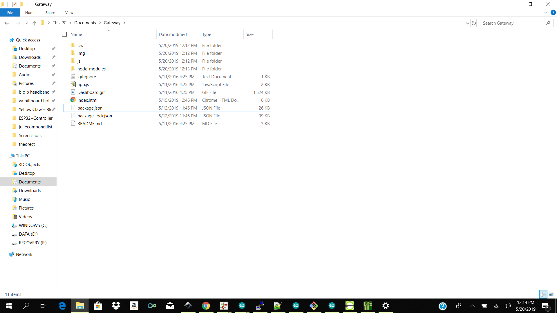
Folder Structure
- node_modules
- public
- css
- img
- js
- index.html
- app.js
- package.json
- package-lock.json
Code Structure
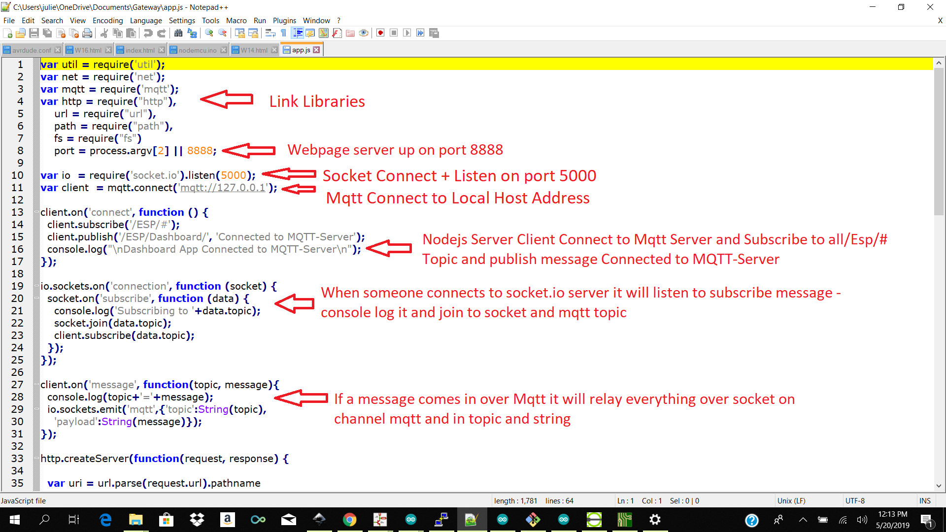
app.js
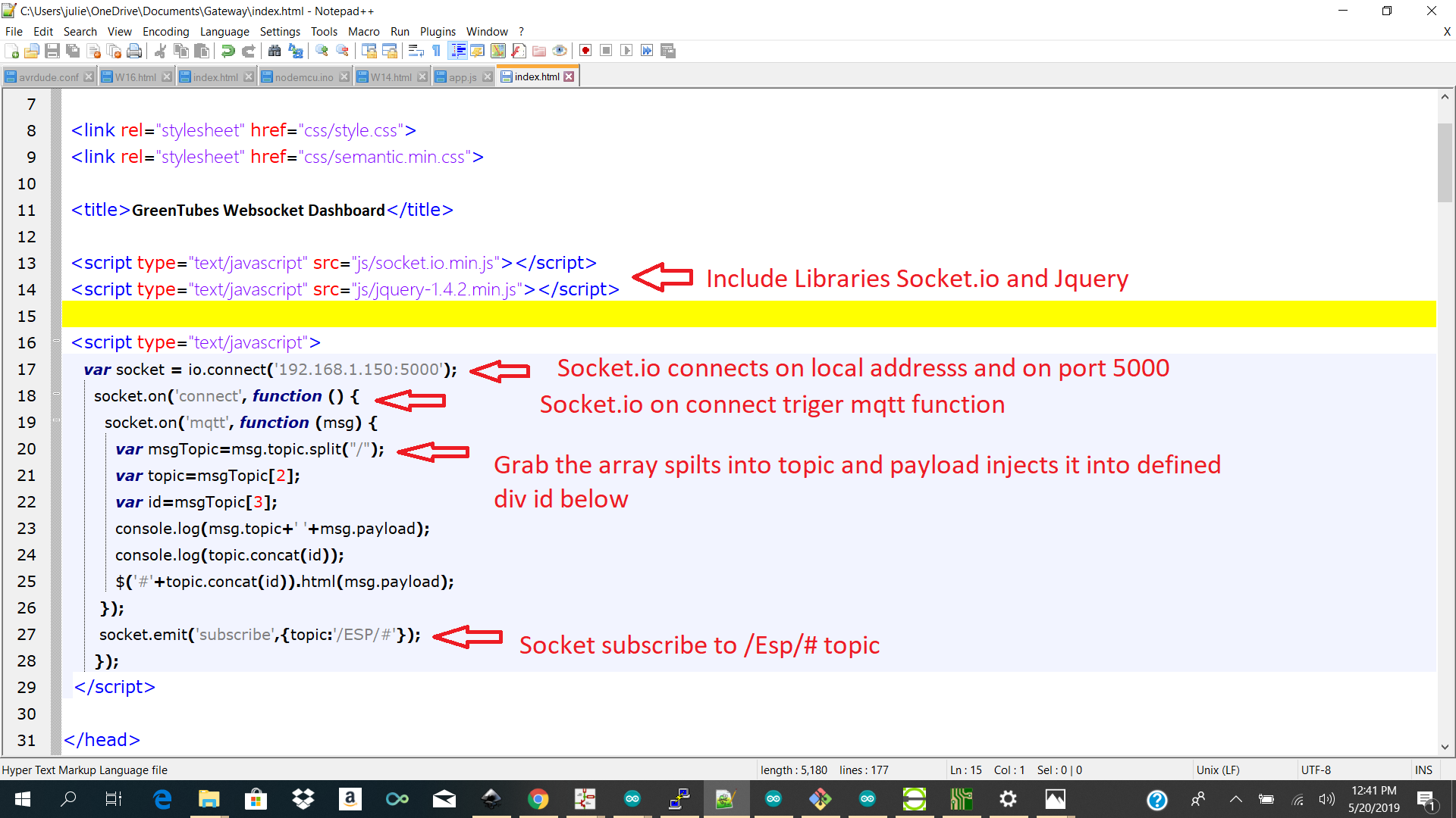
index.html
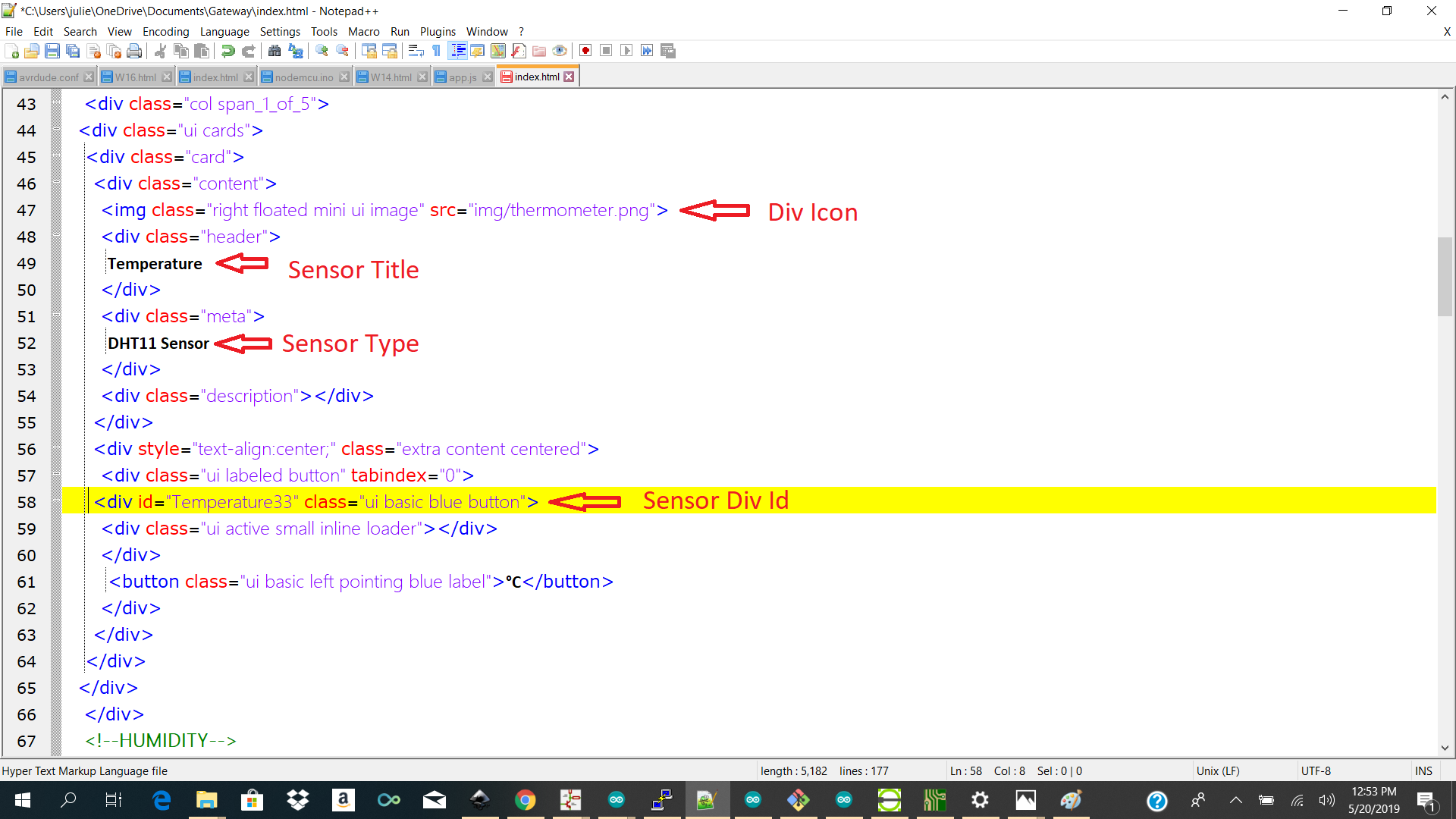
Dashboard
Problem
note: I had to manually install express and edit the app.js file to use express to route my path to find my css files and js files properly. I also moved all my files into a folder call public so that my route could find them.Test 1 Programming Attiny45 with Dht Library
I tested using the attiny 45 to compile my dht library but imidiatly I got storage full issues and no reading from my dht and I decided to move over to a controller with bigger storage which was avalible at our lab and was fimiliar so I took the atmega328p.
I choose to use the atmega328p because it is the same controlled use on the arduino uno so I could do my tests on the arduino uno compile it and then upload it to my custom board.
Test 2 Programming with Arduino Uno
I then started off compiling my code on my arduino uno and do all the tests.
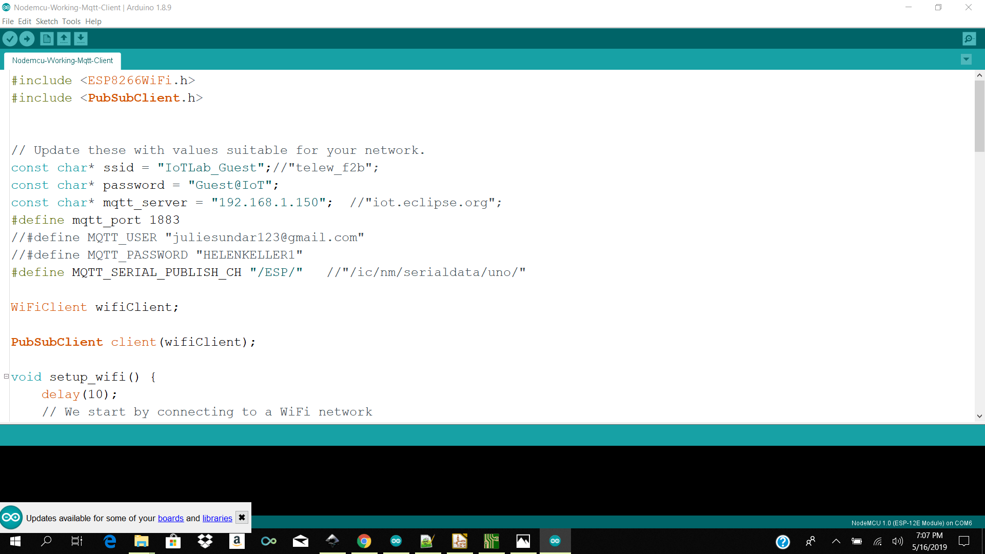
I then started my raspberry which starts my mqtt broker which is running as a daemon and relaying my messages based on my topics to whatever client is subscribing or pubpishing to those topics.
I then start my nodejs app which starts websocket which is subscribing to my temperature humitiy and soild topics and it pushes it to the dashboard widgets
Programming with( Atmega V 2.0)
Pitfals
Unfortunatly before I could attach my temp and humidity and soil sensor to my atmega board my traces got torn and I no longer could upload to the board. I tried making bridges but it did not work.
So I descided to make a new board.. See below the disapointment.
Atmega Redesign 2.0
Desiging using Kicad
Milling and Soldering
Programming it works!! Check below to download my ino files
Download Links Here
Reference
Kicad Sketch Zip /Gerber/Nc
Arduino and Nodemcu Ino
Atmega and Nodemcu Ino
Gatewaydashboard
Contact Us
Where To Find Us
Paramaribo Suriname
Ethnalaan
50..