Mechanical Design/Machine Design
Summary
- Brainstorm/ IDEA Selection
- Digital Artist machine
- Gather Materials / Source Physical Parts
- Split Teams
- Team A: Dave /Thibault / Theo Mechanical Design
- Team B: Shaf /Dave / Elvira Electronics Motor Driver Design
- Team C: Julie / Pascal / John Processing to Serial Communication + Motor Driver Programming
- Group : Documentation
- Coordinator: Theo
- Test Workflow
- Design the 3D Enclosure using CAD Fusion 360
- Lazer Cut the Enclosure using Plywood
- Configure the Raspberry pi and install the Inkscape/Gimp and Grbl2Web Interphase
- Install Grbl on Arduino
- Manually send Gcode from Universal Gcode sender to arduino to convert nc to steps to control stepper motors
- Installing Processing Software
- Test shapes
- Test serial communication
- Optimized niels code for working with our custom motor driver boards
Overly Ambitious Design and Test1
Individual Contribution Final
Designing OVERLY AMBITIOUS DESIGN AND TEST1
Idea:
Digital Artist Project in a snap/ CNC PLOTTER MACHINE The idea is to build a digital artist that makes a photo or uses an uploaded photo (photo booth). How does it work? Automatic Picture vectorization / User Interface (1-2p) The art is created by turning Photos it into Sketch Art (using macro script Gimp on RaspberryPi 2 or 3), vectorize this art convert it into g code and send it to the grbl nc converter / calibrator and then to the XY(Z) motion system.Test Workflow OVERLY AMBITIOUS ARCHITECTURE AND WORKFLOW
Final Workflow
Individual Contribution
Individual Contribution Overly AmbitiousTest1
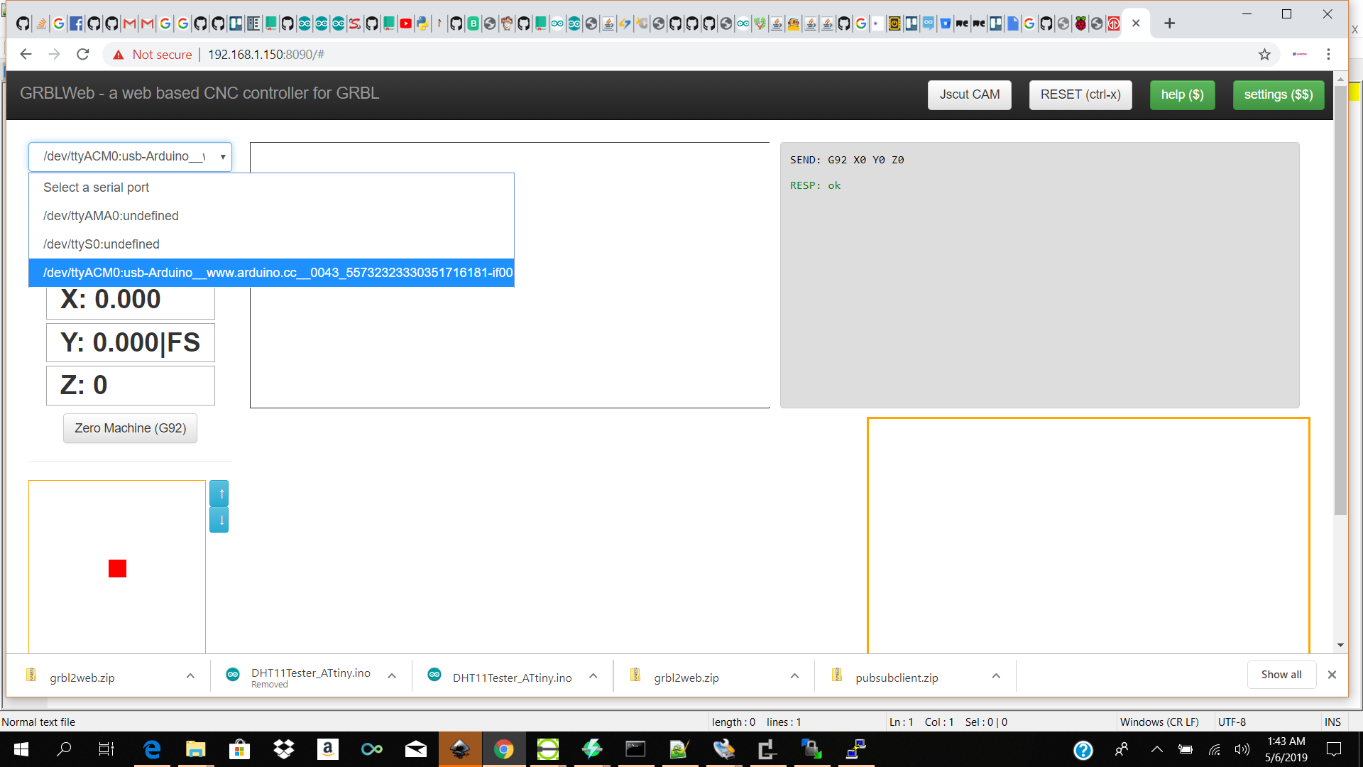
One of the tasks which I contributed in with teammates Pascal was to test the grbl2web interphase which we had to install on the raspberry pi or pc. We tested on windows and mac but we were getting serial port issues so I set up a raspberry3 and ran GRBLSERVER Source
The grblserver is a nodejs application it captures the image in the bacground using mjpeg streamer send it off to be processed and receives gcode and sends the gcode to the arduino over serial.
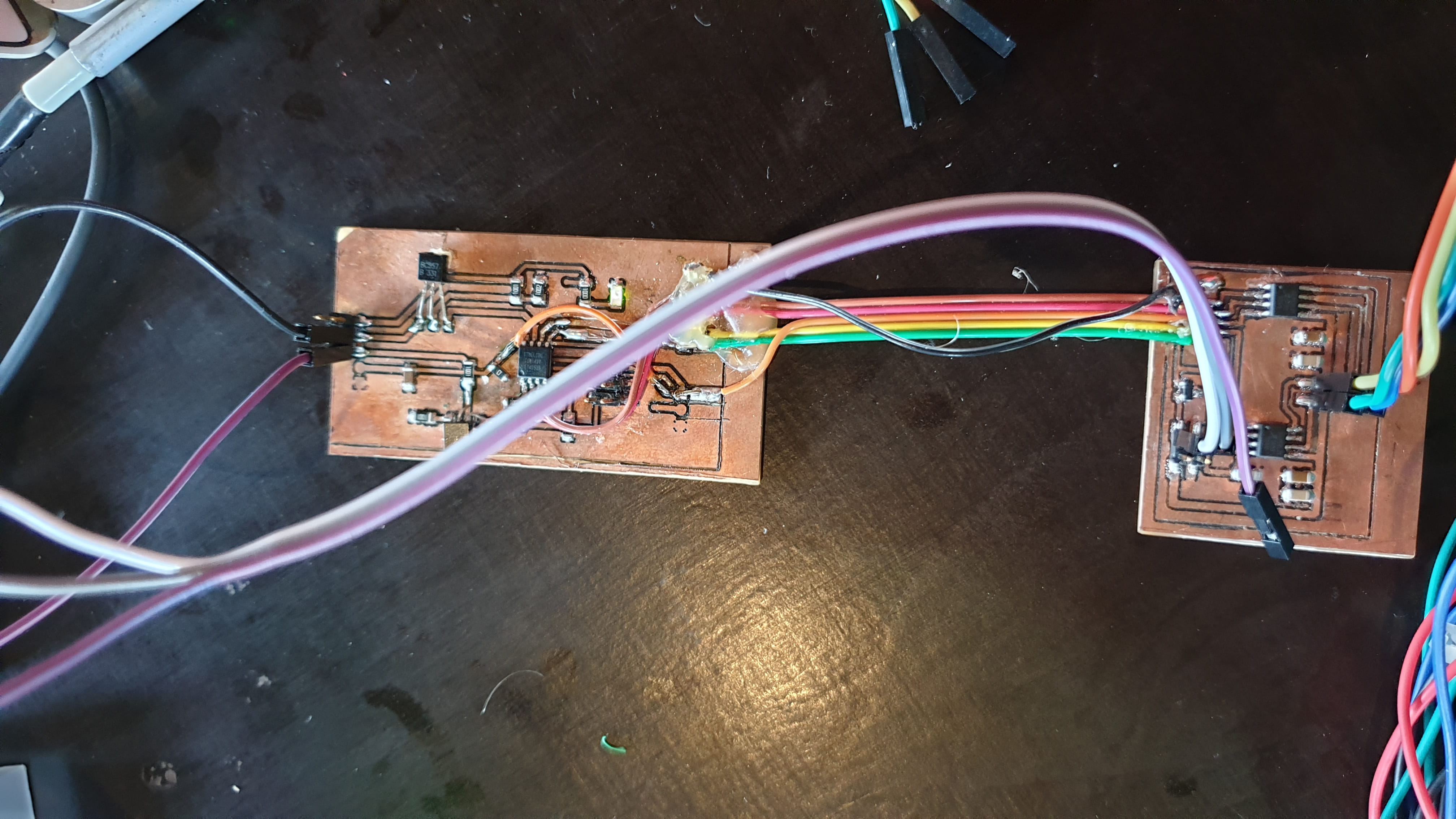
For this week Machine/ Mechanical Design my task was to get the grbl installed on the arduino(for testing) and be able to process the gcode coming over the serial port of the arduino and convert it using grbl parameters into steps to control the stepper motors which was connected to our custom motor drivers (designed by teammate Theo.
The arduino will then be connected to custom step dir motor drivers(designed by Theo which will then be connected to our nema 17 motors
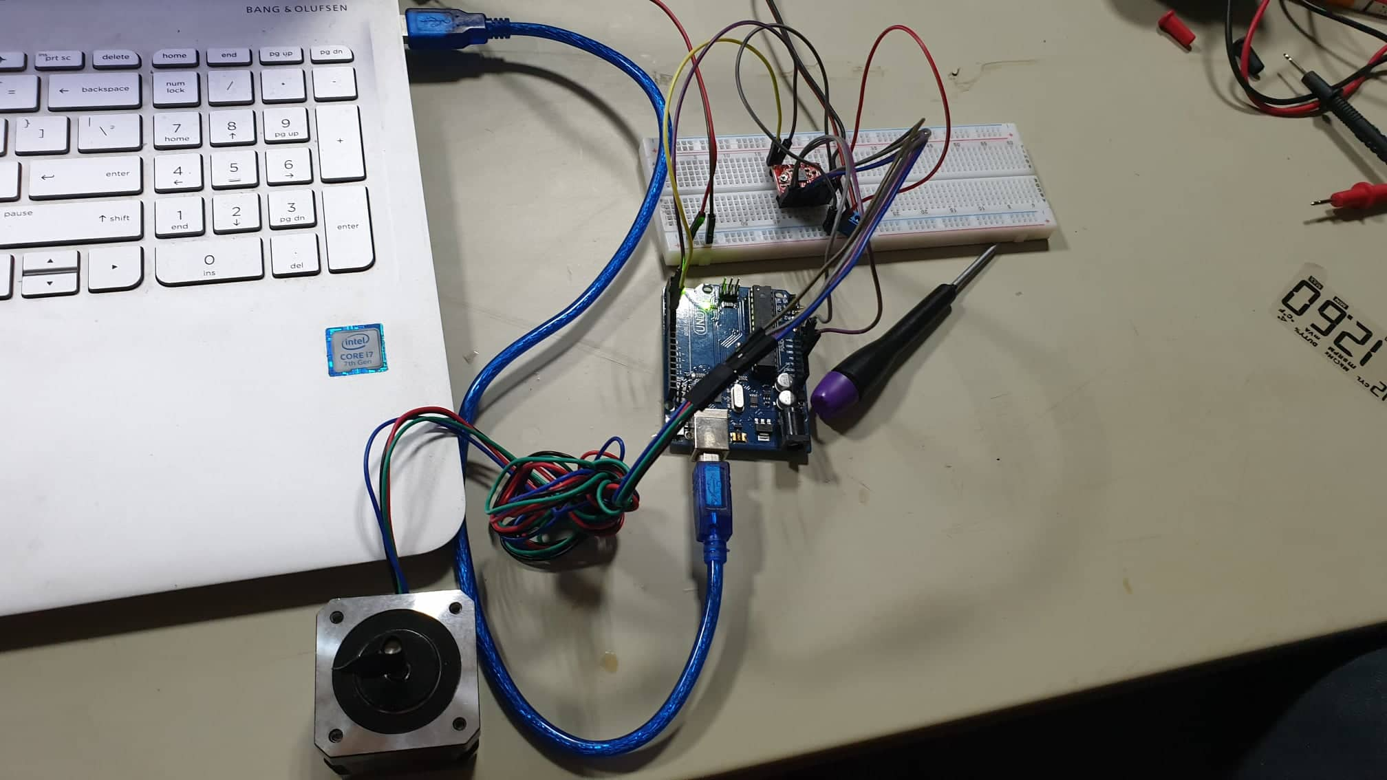
Heardware setup
 note:Comercial motor driver
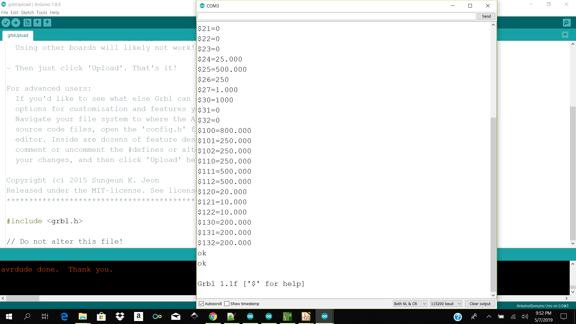
The first thing which I did was to get the grbl library installed (you can find the zip below) and flash the arduino with the grbl example code and it is ready for receiving gcode but before I could control the steppers correctly I needed to either manually add the parameters for my x y or z motors.
To do so after flashing the arduino connected to the correct serial port open serial monitor on baudrate 115200 and you should get a response grbl in the search you can type $$ to see your parameters you could manually change the parameters there or use the grbl calculatorhere
The final test which I did was to install the gcode sender chrome extenstion to test sending manula gcode to the arduino with grbl library installed to see if it can control the nema stepper motor via the step dir pins and it worked but the issue was that the motor was gittering.
I assume that it could be because we did not configure the grbl parameters properly or our power cables we too thin and was not holding the voltage.
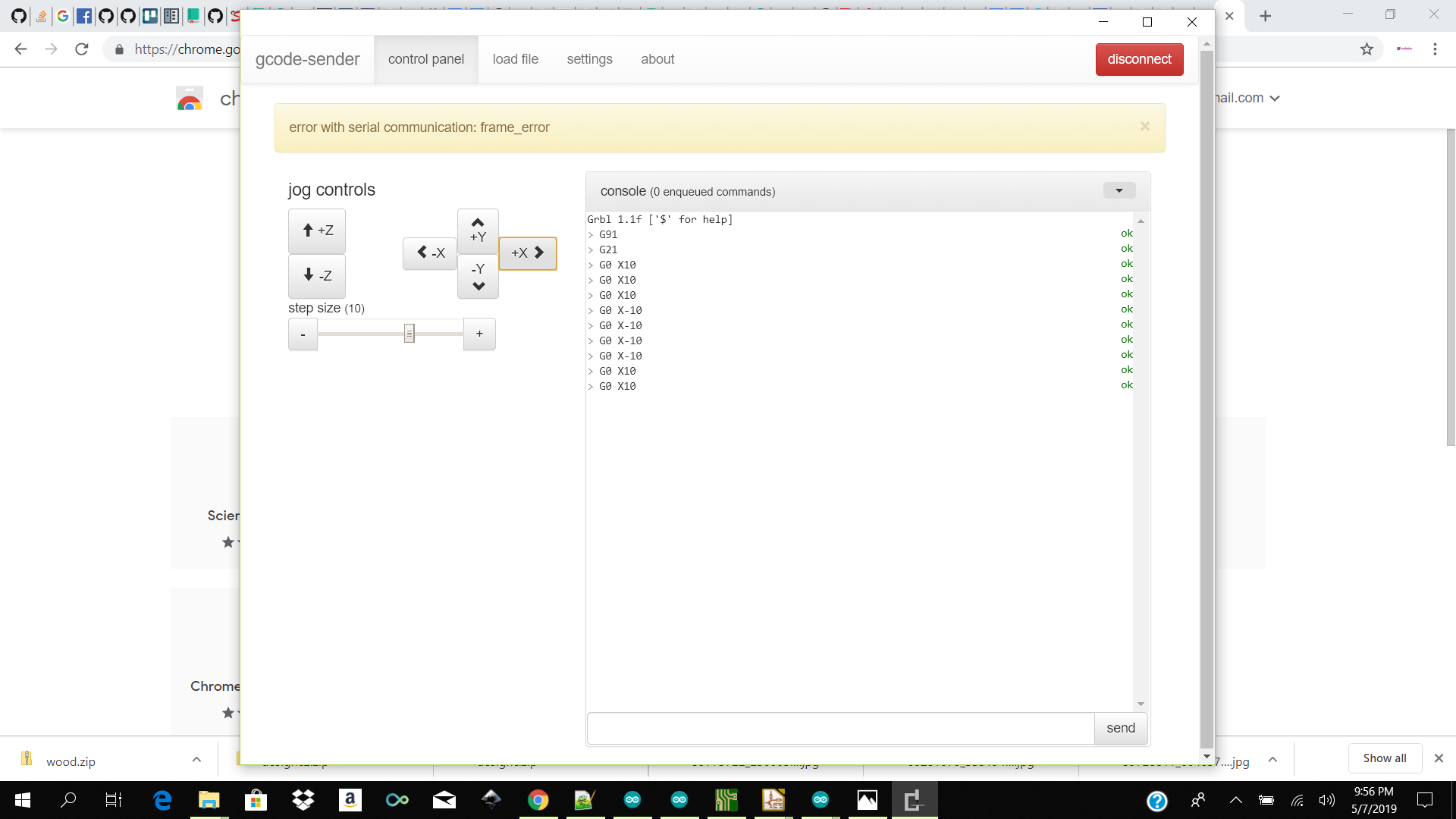 Chrome extenstion
Individual Contribution Final
After a few discussion and testing of which design and architecture we would like to go with we ended up desiging and building a simple to use shape plotting machine with a simple proesing interphase.
My input was to work with Pacal and John to get the data from processing interphase over serial to the motor drivers which would interpret those comands and send coordinartes to the stepper motors.
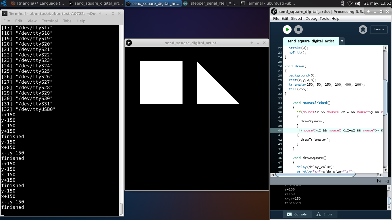
After a few tirals and erros we finaly got it to work. We were able to get two basic shapes a square and triangle to sent over serial to the motor drivers and drawn out my the digial artist
The boards control X and Y movements. We use a modification of Neil’s code for stepper control and serial communication (hello.stepper.bipolar.44.full.c and hello.ftdi.44.echo.c). We are networking, using serial bus, and currently, taking commands from the computer, with the Processing interface through ftdi cable.
Code
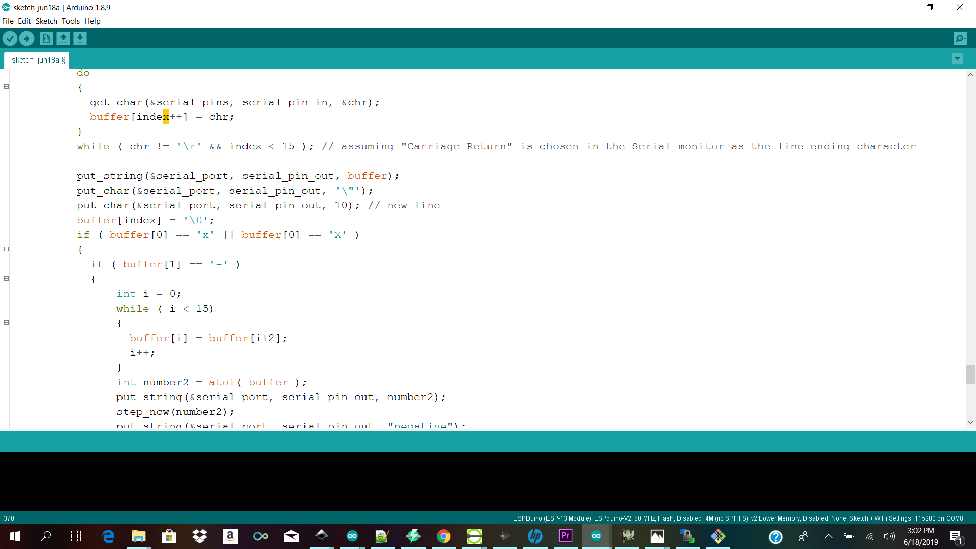 The main part of the code first tests for the axis (x or y), then for the direction (+ or -), then shifts the content of the buffer and converts it to an integer, which is the argument for the n steps routine.
Processing
Download Links Here
GRBL ZIP ARDUINO UNO
Stepper Driver Code and Processing
Contact Us
Where To Find Us
Paramaribo Suriname
Ethnalaan
50..