Networking and Communications
Assignments
Introduction
Electronic communication is a general term that embraces all kinds of computer-mediated communication in which individuals exchange messages with others, either individually or in groups.What does Network mean? A network, in computing, is a group of two or more devices that can communicate. In practice, a network is comprised of a number of different computer systems connected by physical and/or wireless connections.

So in this week I have desided to make a wired network using I2C protocol. Before that let's understand about the basic nework protocols.
I2C
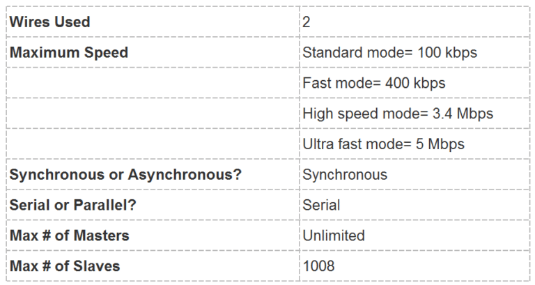
I2C combines the best features of SPI and UARTs. With I2C, you can connect multiple slaves to a single master and you can have multiple masters controlling single, or multiple slaves. This is really useful when you want to have more than one microcontroller logging data to a single memory card or displaying text to a single LCD.
I2C only uses two wires to transmit data between devices:
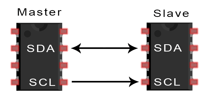
SDA (Serial Data) – The line for the master and slave to send and receive data.
SCL (Serial Clock) – The line that carries the clock signal.
I2C is a serial communication protocol, so data is transferred bit by bit along a single wire (the SDA line).I2C is synchronous, so the output of bits is synchronized to the sampling of bits by a clock signal shared between the master and the slave. The clock signal is always controlled by the master.
With I2C, data is transferred in messages. Messages are broken up into frames of data. Each message has an address frame that contains the binary address of the slave, and one or more data frames that contain the data being transmitted. The message also includes start and stop conditions, read/write bits, and ACK/NACK bits between each data frame
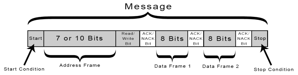
Start Condition: The SDA line switches from a high voltage level to a low voltage level before the SCL line switches from high to low.
Stop Condition: The SDA line switches from a low voltage level to a high voltage level after the SCL line switches from low to high.
Address Frame: A 7 or 10 bit sequence unique to each slave that identifies the slave when the master wants to talk to it.
(Source:http://www.circuitbasics.com/basics-of-the-spi-communication-protocol/)
SPI
SPI is a common communication protocol used by many different devices. For example, SD card modules, RFID card reader modules, and 2.4 GHz wireless transmitter/receivers all use SPI to communicate with microcontrollers.One unique benefit of SPI is the fact that data can be transferred without interruption. Any number of bits can be sent or received in a continuous stream. With I2C and UART, data is sent in packets, limited to a specific number of bits. Start and stop conditions define the beginning and end of each packet, so the data is interrupted during transmission.Devices communicating via SPI are in a master-slave relationship. The master is the controlling device (usually a microcontroller), while the slave (usually a sensor, display, or memory chip) takes instruction from the master. The simplest configuration of SPI is a single master, single slave system, but one master can control more than one slave
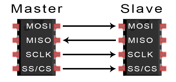
MOSI (Master Output/Slave Input) – Line for the master to send data to the slave.
MISO (Master Input/Slave Output) – Line for the slave to send data to the master.
SCLK (Clock) – Line for the clock signal.
SS/CS (Slave Select/Chip Select) – Line for the master to select which slave to send data to.
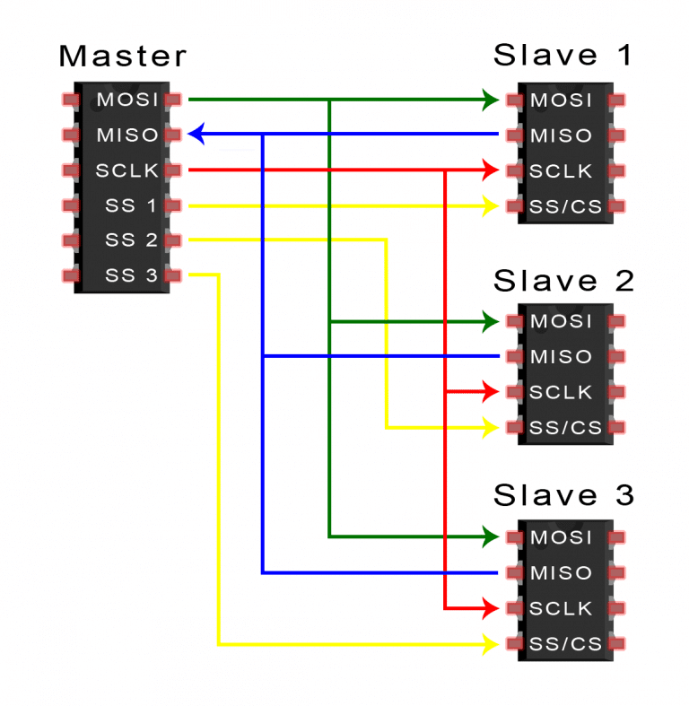
SPI can be set up to operate with a single master and a single slave, and it can be set up with multiple slaves controlled by a single master. There are two ways to connect multiple slaves to the master. If the master has multiple slave select pins, the slaves can be wired in parallel like this:
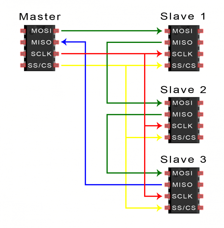
If only one slave select pin is available, the slaves can be daisy-chained like this:
STEPS OF SPI DATA TRANSMISSION
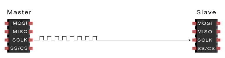
1. The master outputs the clock signal:
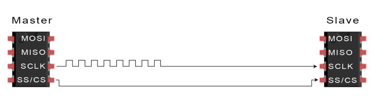
2. The master switches the SS/CS pin to a low voltage state, which activates the slave:
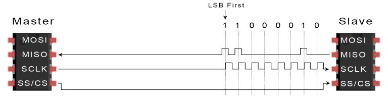
3. The master sends the data one bit at a time to the slave along the MOSI line. The slave reads the bits as they are received:
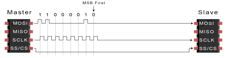
4. If a response is needed, the slave returns data one bit at a time to the master along the MISO line. The master reads the bits as they are received:
(Source:http://www.circuitbasics.com/basics-of-the-spi-communication-protocol/)
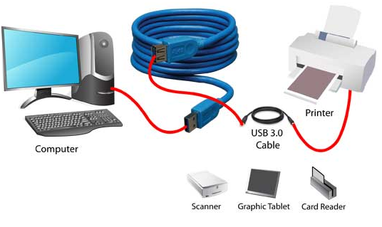
USB
USB stands for universal serial bus. Again it is a serial communication of two wire protocol. The data cable signal lines are labeled D+ and D-.This protocol is used to communicate with the system peripherals.USB protocol is used to send and receive the data serially to the host and peripheral devices.USB communication requires a driver software which is based on the functionality of the system.USB device can transfer data on the bus without any request on the host computer. Now a day’s most of the devices are using this technique for communicating with USB protocol. Like computer to communicate with ARM controller using USB. USB transfer the data different modes .first one is slow speed mode 10kbps to 100 kbps; second one is full speed mode 500kbps to 10mbps, high speed mode 25mbps to 400 mbps.USB maximum cable length of 4 meters.
(Source:https://www.elprocus.com/communication-protocols/)
Board designing
So for I2C networking, I took my previously done assignments. Some of them were damaged. But I replaced them with new boards.
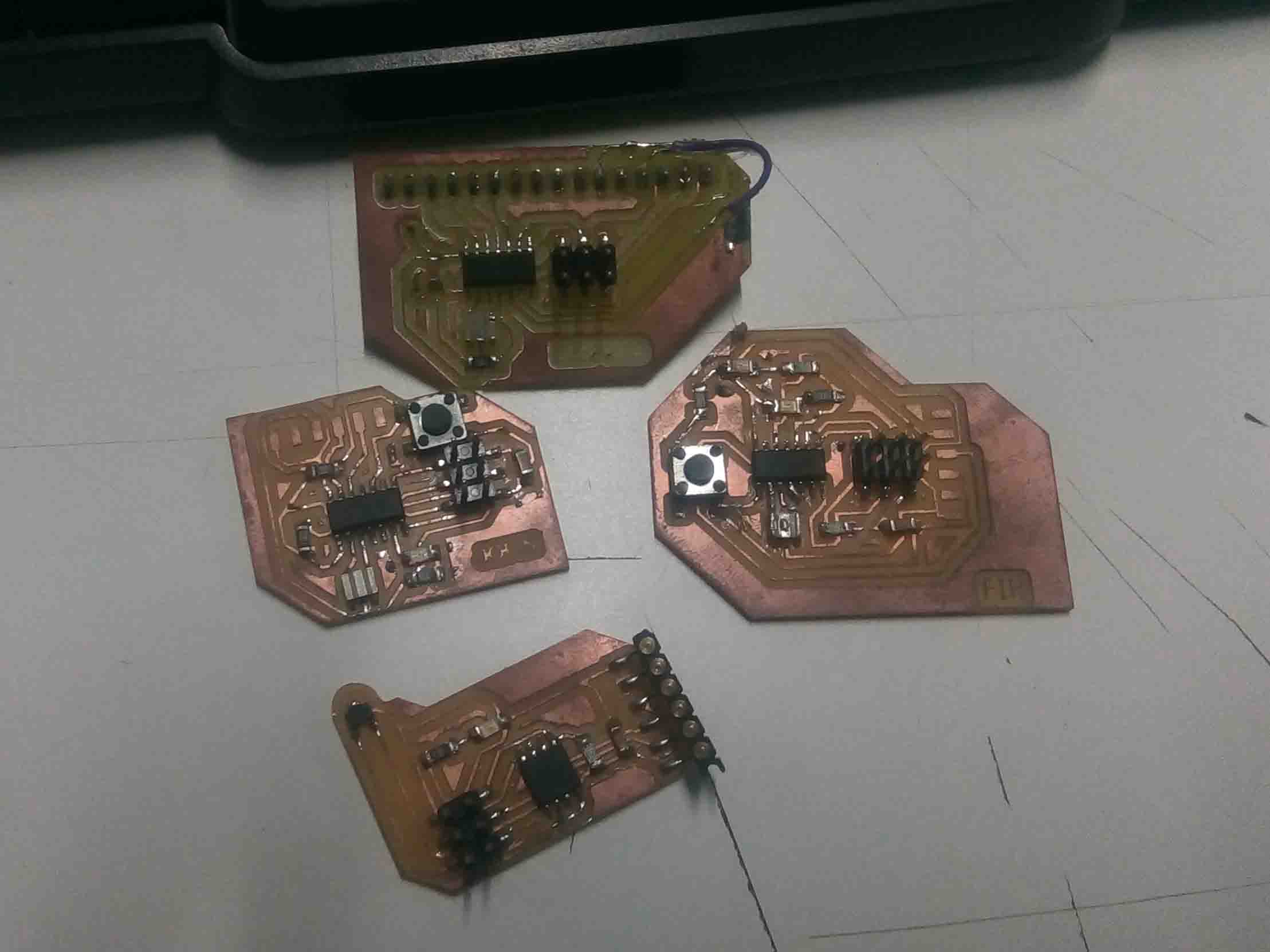
So I have descided to used these following boards
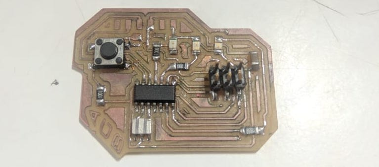
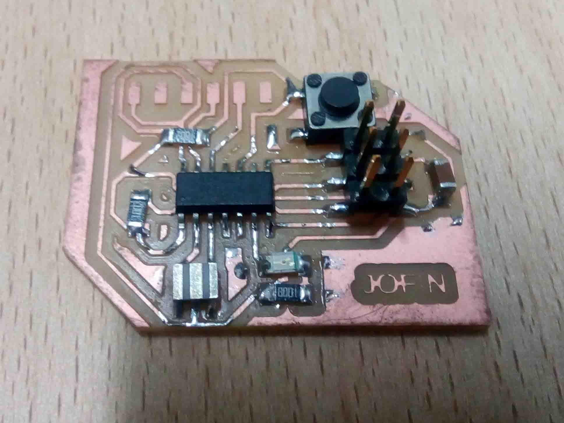
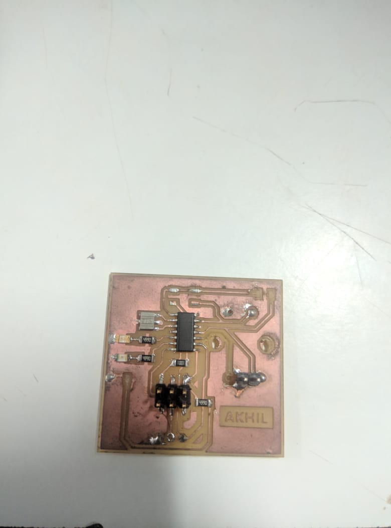
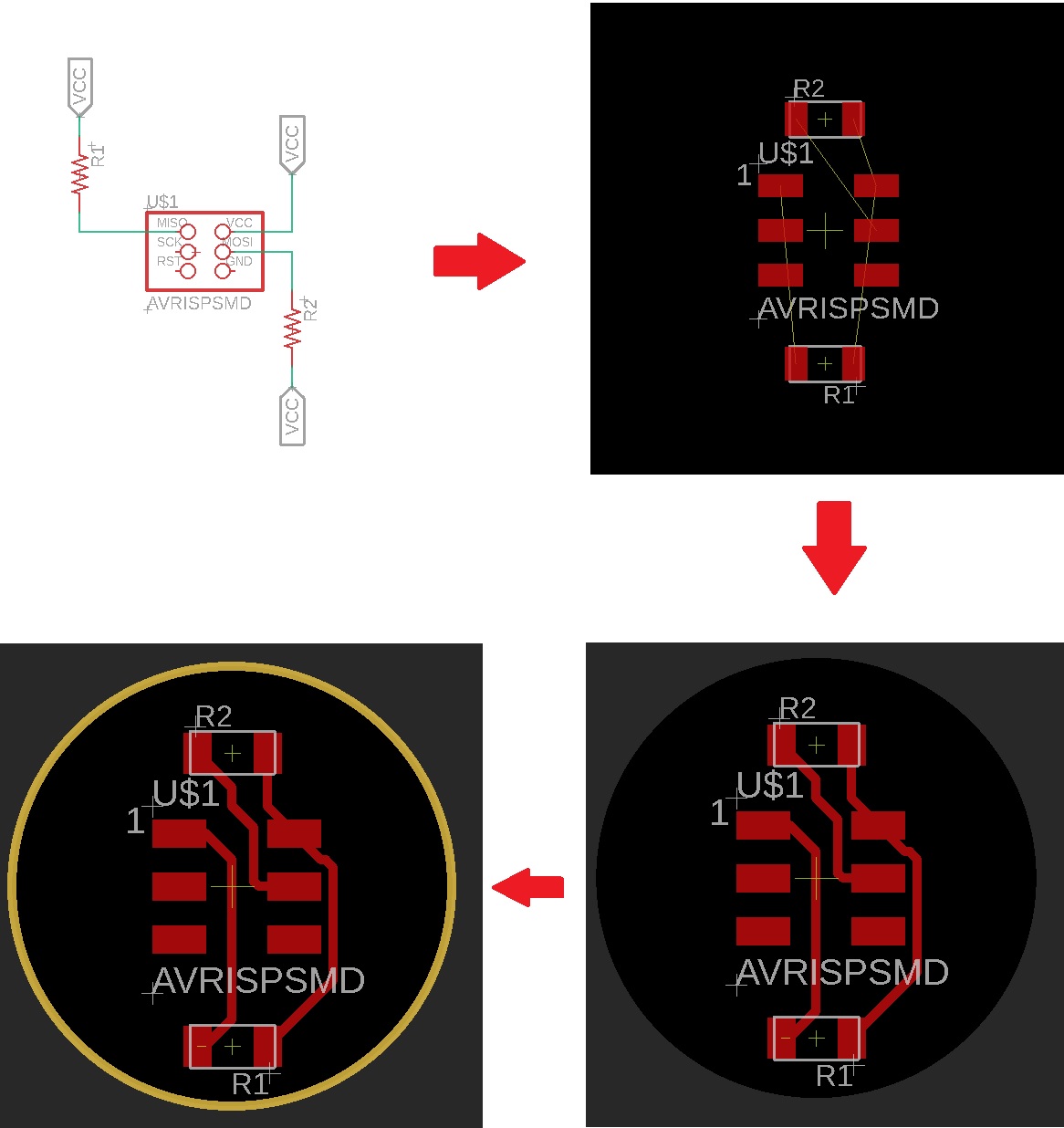
For connecting them in I2C format, we need to connect them in specific manner. Layout is given below
Now let's program this boards.
Programming
The attiny 44 needs an additional software support as compared to arduino. So the library Wire.h won't work in the same attiny. So I have found an ther library called "TinyWire". You can download it below.
So let's start programming. Here is the master board code
#include <TinyWire.h>

#define BTN 3 // Button connected to Digital Pin 3
#define LED 7 // LED connected to Digital Pin 7

byte slave_1 = 10; //Slave address

void setup() {

pinMode( BTN, INPUT_PULLUP); // intializing Button
pinMode( LED, OUTPUT); // intializing LED
TinyWire.begin(); // intializing Communication
}

void loop() {

if(digitalRead(BTN)==LOW) //If button is pressed
{
digitalWrite(LED,HIGH); // led turns on
TinyWire.beginTransmission(slave_1); // begin transmission to slavve board
TinyWire.send('y'); // Sending a message
TinyWire.endTransmission(); // ending the transmission


}
else
{
digitalWrite(LED,LOW); // if button is released
TinyWire.beginTransmission(slave_1);// begin transmission to slavve board
TinyWire.send('n');// Sending a message
TinyWire.endTransmission();// ending the transmission
}

}
Here is the slave code
#include <TinyWire.h>
#define LED1 7 //led 1 connected to 7
#define LED2 8 //led 2 connected to 8
byte slave_1 = 10; // slave address

void setup() {

TinyWire.begin(slave_1);
pinMode(LED1, OUTPUT); //initializing led1
pinMode(LED2, OUTPUT); //initializing led2
}

void loop() {
 byte data; // delacring data
if (TinyWire.available()) // check whether master is available
 data = TinyWire.receive(); // storing recieved data
if (data == ('y')){ //if recieved data is "y"
digitalWrite(LED1, HIGH); // led 1 on
digitalWrite(LED2, HIGH); // led 2 on
delay(500); //halt for 500 milliseconds
digitalWrite(LED1, LOW); // led 1 off
digitalWrite(LED2, LOW); // led 2 off
delay(500);//halt for 500 milliseconds
}
else if (data == ('n')){ //if recieved data is "n"
digitalWrite(LED1, LOW); // led 1 off
digitalWrite(LED2, LOW); // led 2 off
}
}
Here is the test video..
So it was a success. Now I have to address these board and add one more to the list. For that First I had to make some changes in the master code..
Here is the revised master code
#include <TinyWire.h>

#define BTN 3 // Button connected to Digital Pin 3
#define LED 7 // LED connected to Digital Pin 7

byte slave_1 = 10; //Slave 1 address
byte slave_2 = 8;  //slave 2 address


void setup() {

pinMode( BTN, INPUT_PULLUP); // intializing Button
pinMode( LED, OUTPUT); // intializing LED
TinyWire.begin(); // intializing Communication
}

void loop() {

if(digitalRead(BTN)==LOW) //If button is pressed
{
digitalWrite(LED,HIGH); // led turns on
TinyWire.beginTransmission(slave_1); // begin transmission to slavve board
TinyWire.send('y'); // Sending a message
TinyWire.endTransmission(); // ending the transmission

TinyWire.beginTransmission(slave_2);
TinyWire.send('n'); // Sending a message
TinyWire.endTransmission(); // ending the transmission


}
else
{
digitalWrite(LED,LOW); // if button is released
TinyWire.beginTransmission(slave_1);// begin transmission to slavve board
TinyWire.send('n');// Sending a message
TinyWire.endTransmission();// ending the transmission

TinyWire.beginTransmission(slave_2);
TinyWire.send('y'); // Sending a message
TinyWire.endTransmission(); // ending the transmission
}

}
Here is the slave 2 Code
#include <TinyWire.h>
#define LED1 7 //led 1 connected to 7

byte slave_2 = 8; // slave 2 address

void setup() {

TinyWire.begin(slave_2);
pinMode(LED1, OUTPUT); //initializing led1

}

void loop() {
 byte data; // delacring data
if (TinyWire.available()) // check whether master is available
 data = TinyWire.receive(); // storing recieved data
if (data == ('y')){ //if recieved data is "y"
digitalWrite(LED1, HIGH); // led 1 on

delay(500); //halt for 500 milliseconds
digitalWrite(LED1, LOW); // led 1 off

delay(500);//halt for 500 milliseconds
}
else if (data == ('n')){ //if recieved data is "n"
digitalWrite(LED1, LOW); // led 1 off

}
}
Here is the test video..
Group Assignment
My friend Joel Made a Wi-Fi board using ESP8266. So I would like to make somthing interesting. Full PCB files Avialable in Joel's Page
Here is the code
 #include <ESP8266WiFi.h>

#include "WemoSwitch.h"
#include "WemoManager.h"
#include "CallbackFunction.h"

boolean connectWifi();

 void lightOn();
 void lightOff();
 void secondOn();
   void secondOff();
  char ssid[] = "Wi-Fi Username";
 char password[] = "Wi-Fi Password";
 WemoManager wemoManager;
  WemoSconst int ledPin = 13;
void setup()
  {
Serial.begin(115200);
 WiFi.mode(WIFI_STA);
 WiFi.disconnect();
  delay(100);
 Serial.print("Connecting Wifi: ");
  Serial.println(ssid);
 WiFi.begin(ssid, password);
 while (WiFi.status() != WL_CONNECTED) {
  Serial.print(".");
    delay(500);
  }
    Serial.println("");
         Serial.println("WiFi connected");
    Serial.println("IP address: ");
 IPAddress ip = WiFi.localIP();
 Serial.println(ip);
  wemoManager.begin();
  light = new WemoSwitch("light", 80, lightOn, lightOff);
   wemoManager.addDevice(*light);
    pinMode(ledPin, OUTPUT);
 delay(10);
 digitalWrite(ledPin, HIGH);
     }
        void loop()
     {
      wemoManager.serverLoop();
      }
     void lightOn() {
      Serial.print("Switch 1 turn on ...");
  digitalWrite(ledPin, HIGH);
   }
 void lightOff() {
    Serial.print("Switch 1 turn off ...");
       digitalWrite(ledPin, LOW);
     }
You can download the files from Here..