Output devices
Assignments
Output devices
What does Output Device mean? An output device is any device used to send data from a computer to another device or user. Most computer data output that is meant for humans is in the form of audio or video. Thus, most output devices used by humans are in these categories. Examples include monitors, projectors, speakers, headphones and printers.

So as the part of output devices, I am going to make lcd display to show some output. So let'sget started....
Liquid Crystal Display
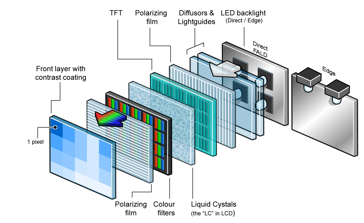
The principle behind the LCD’s is that when an electrical current is applied to the liquid crystal molecule, the molecule tends to untwist. This causes the angle of light which is passing through the molecule of the polarized glass and also cause a change in the angle of the top polarizing filter. As a result a little light is allowed to pass the polarized glass through a particular area of the LCD. Thus that particular area will become dark compared to other. The LCD works on the principle of blocking light. While constructing the LCD’s, a reflected mirror is arranged at the back. An electrode plane is made of indium-tin oxide which is kept on top and a polarized glass with a polarizing film is also added on the bottom of the device. The complete region of the LCD has to be enclosed by a common electrode and above it should be the liquid crystal matter.
Next comes to the second piece of glass with an electrode in the form of the rectangle on the bottom and, on top, another polarizing film. It must be considered that both the pieces are kept at right angles. When there is no current, the light passes through the front of the LCD it will be reflected by the mirror and bounced back. As the electrode is connected to a battery the current from it will cause the liquid crystals between the common-plane electrode and the electrode shaped like a rectangle to untwist. Thus the light is blocked from passing through. That particular rectangular area appears blank.
How LCDs are Constructed?
The glass which does not have a polarized film on the surface of it must be rubbed with a special polymer which will create microscopic grooves on the surface of the polarized glass filter. The grooves must be in the same direction of the polarized film. Now we have to add a coating of pneumatic liquid phase crystal on one of the polarized filter of the polarized glass. The microscopic channel cause the first layer molecule to align with filter orientation. When the right angle appears at the first layer piece, we should add a second piece of glass with the polarized film. The first filter will be naturally polarized as the light strikes it at the starting stage
Thus the light travels through each layer and guided on the next with the help of molecule. The molecule tends to change its plane of vibration of the light in order to match their angle. When the light reaches to the far end of the liquid crystal substance, it vibrates at the same angle as that of the final layer of the molecule vibrates. The light is allowed to enter into the device only if the second layer of the polarized glass matches with the final layer of the molecule.
(Source:https://www.elprocus.com/ever-wondered-lcd-works/)
16X2 LCD
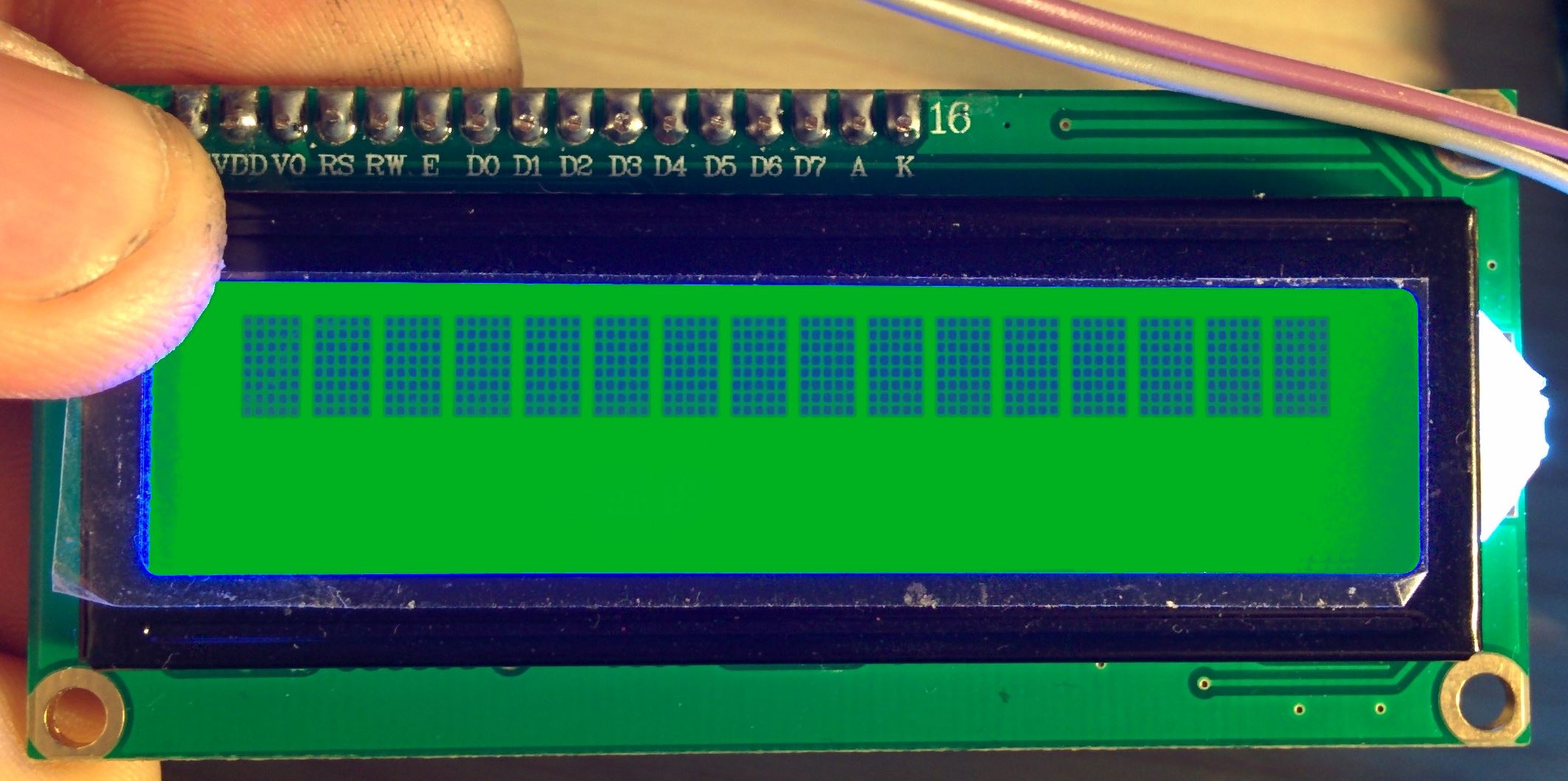
LCD (Liquid Crystal Display) screen is an electronic display module and find a wide range of applications. A 16x2 LCD display is very basic module and is very commonly used in various devices and circuits. These modules are preferred over seven segments and other multi segment LEDs. The reasons being: LCDs are economical; easily programmable; have no limitation of displaying special & even custom characters (unlike in seven segments), animations and so on.
A 16x2 LCD means it can display 16 characters per line and there are 2 such lines. In this LCD each character is displayed in 5x7 pixel matrix. This LCD has two registers, namely, Command and Data. The command register stores the command instructions given to the LCD. A command is an instruction given to LCD to do a predefined task like initializing it, clearing its screen, setting the cursor position, controlling display etc. The data register stores the data to be displayed on the LCD. The data is the ASCII value of the character to be displayed on the LCD. Click to learn more about internal structure of a LCD.You can download the datasheet from Here.
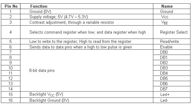
Pin Diagram:
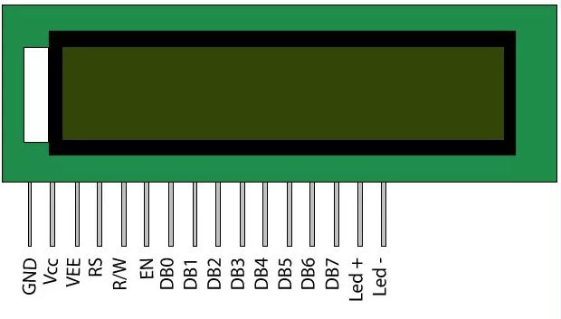
Pin Description:
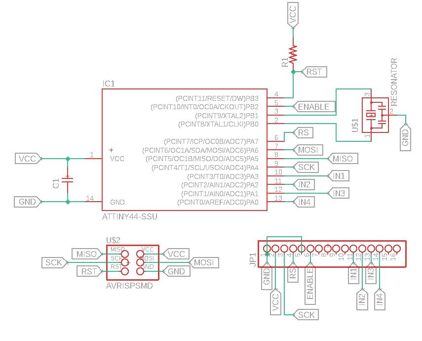
Circuit Design
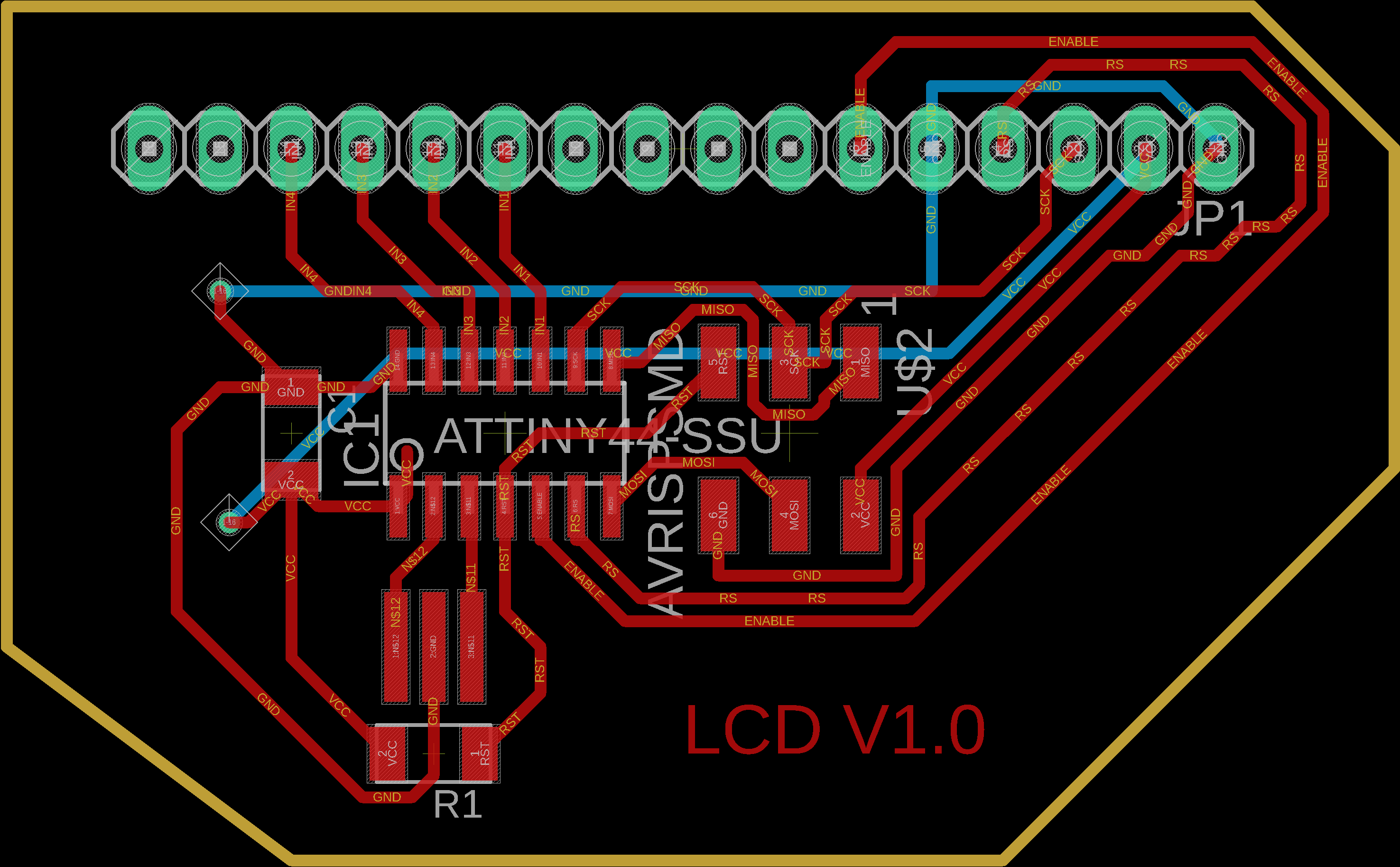
So as I did in previous weeks, I used Eagle software to make the circuit. I used an Attiny44 as micro-controller for the whole circuit...
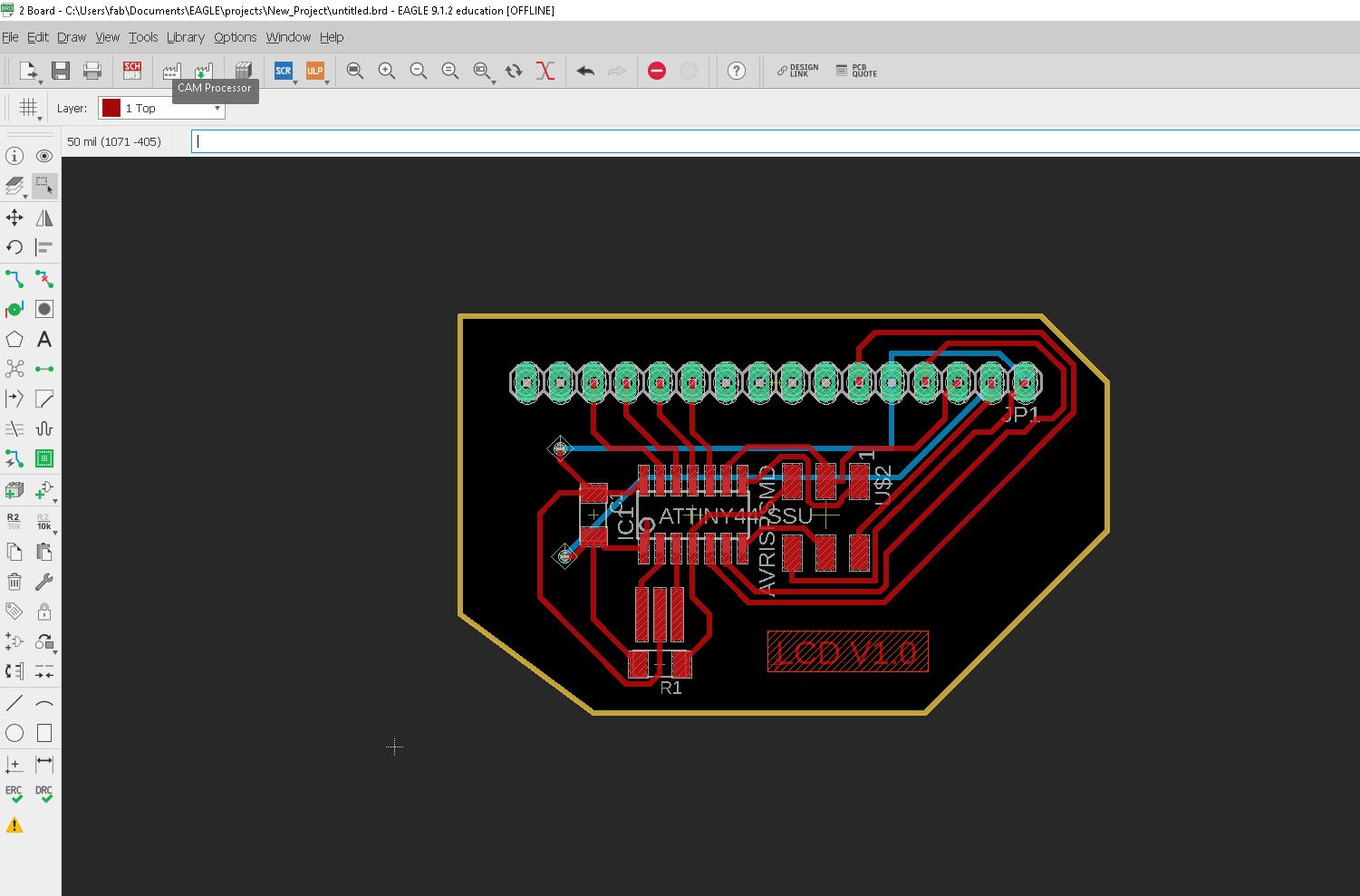
Now shift to PCB mode and route all the connections together.
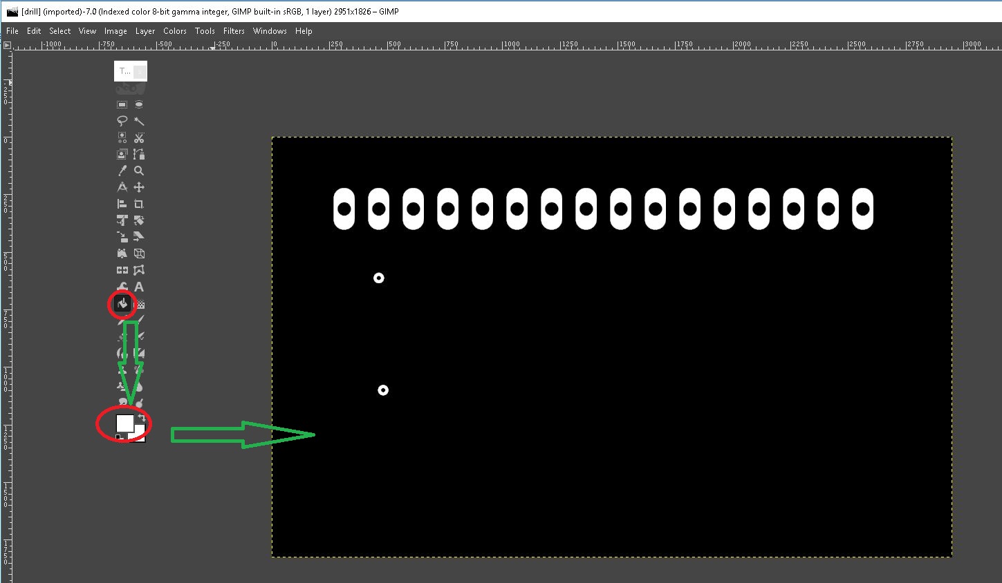
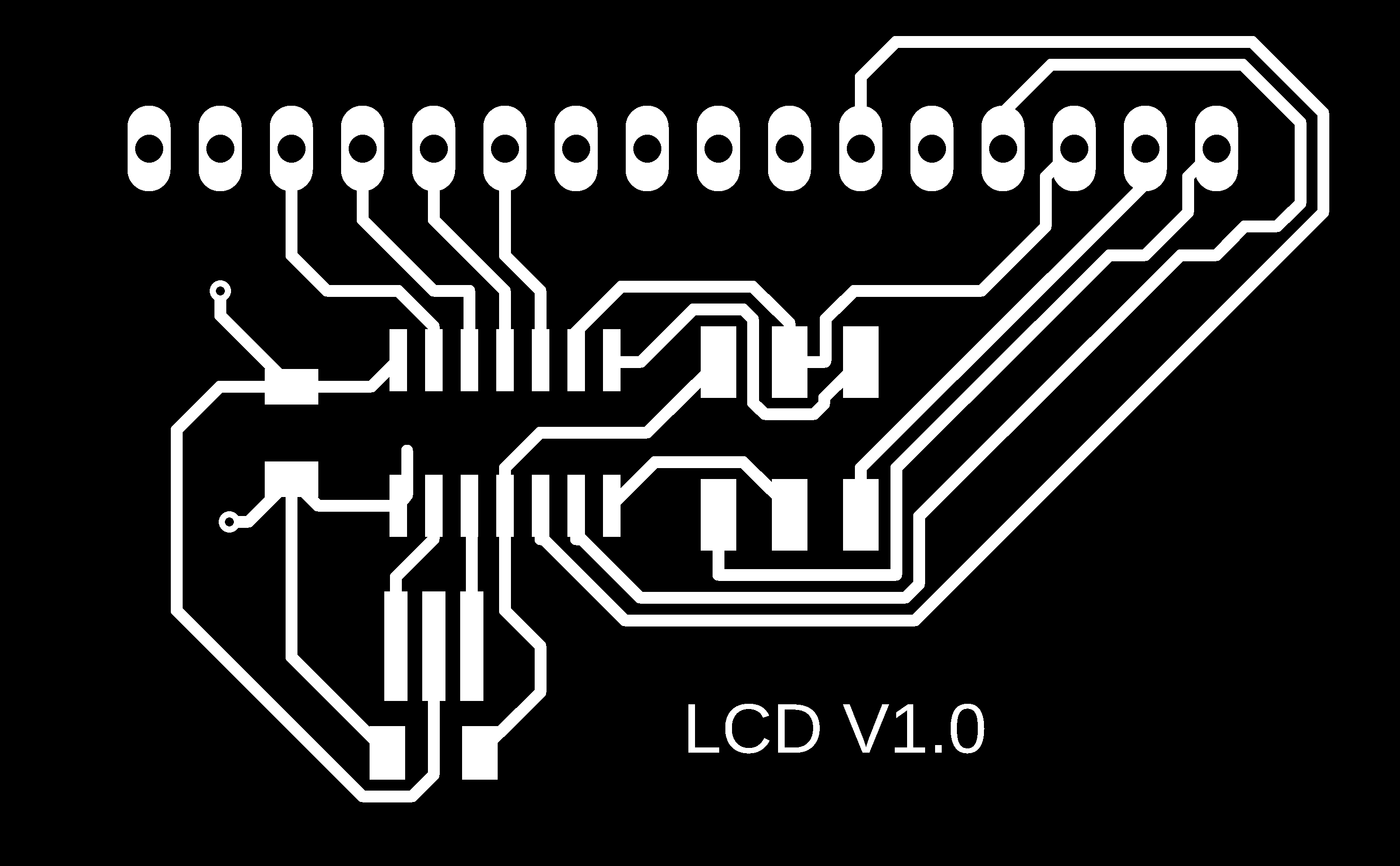
Now "Export" as .png of "Traces", "Drill holes", and "Cut". When I export all the layouts, there was an exception in the holes layouts.
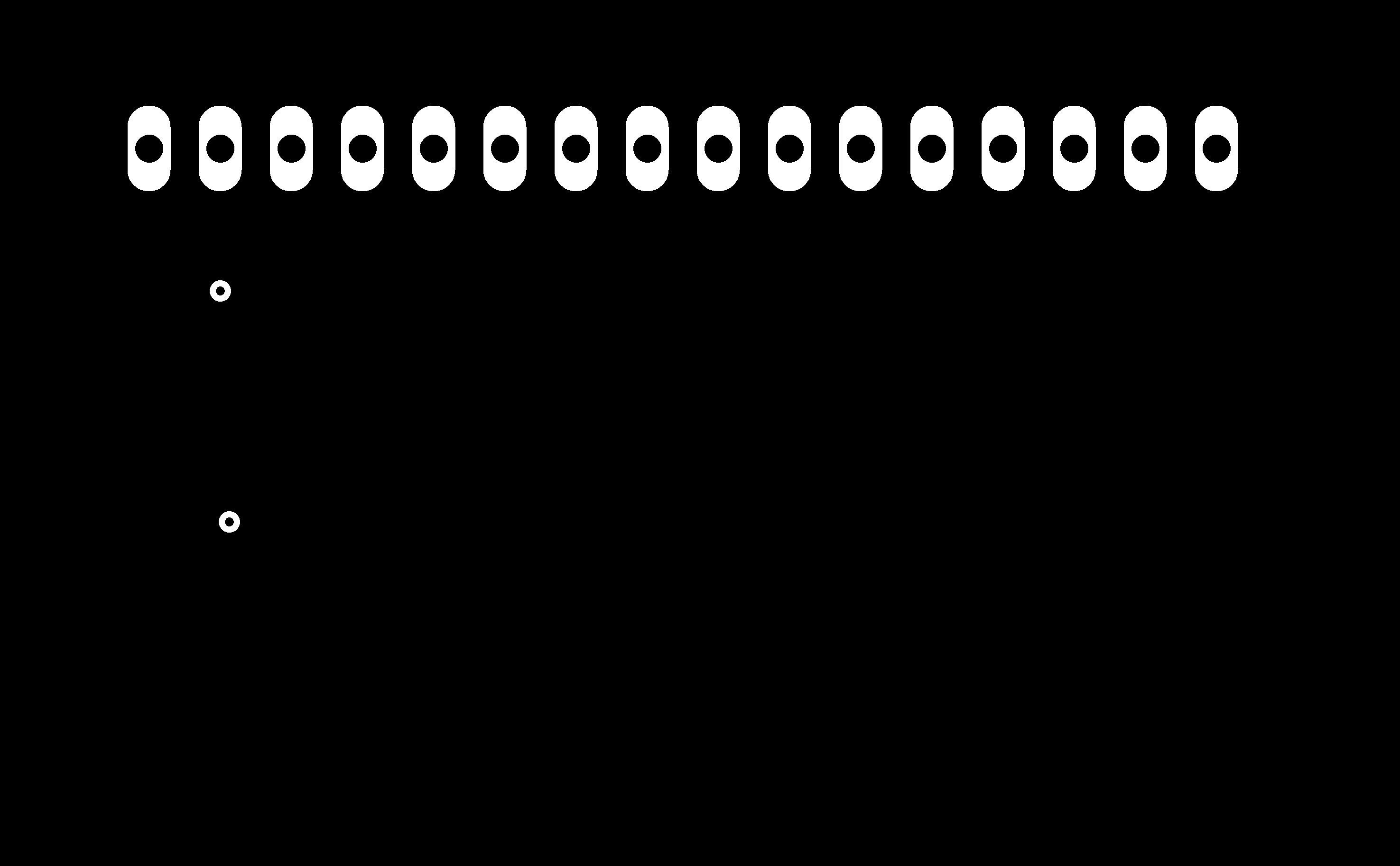
So for fixing this problem, I load the image into "Gimp". I use the fill tool and make colour "white". I change the background colour from black to white.
Here is the files..
Full Layout:
Mill Trace:
Drill Holes:

Cut Trace:

You can download the whole project from here.
PCB Production
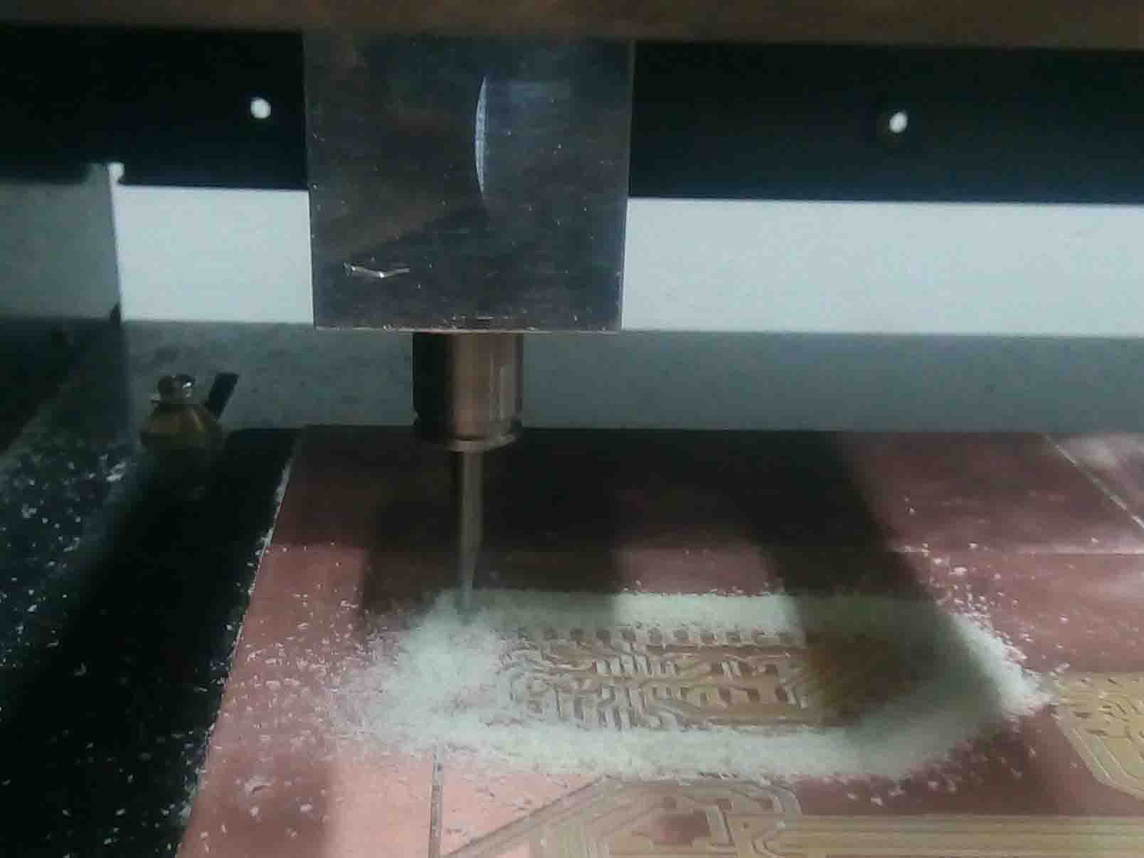
So like I did in the the previous weeks I load the images into fab mods and take modella to make the PCB
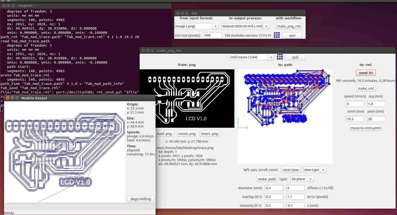
I used a 1/64 inch V-bit for milling the traces
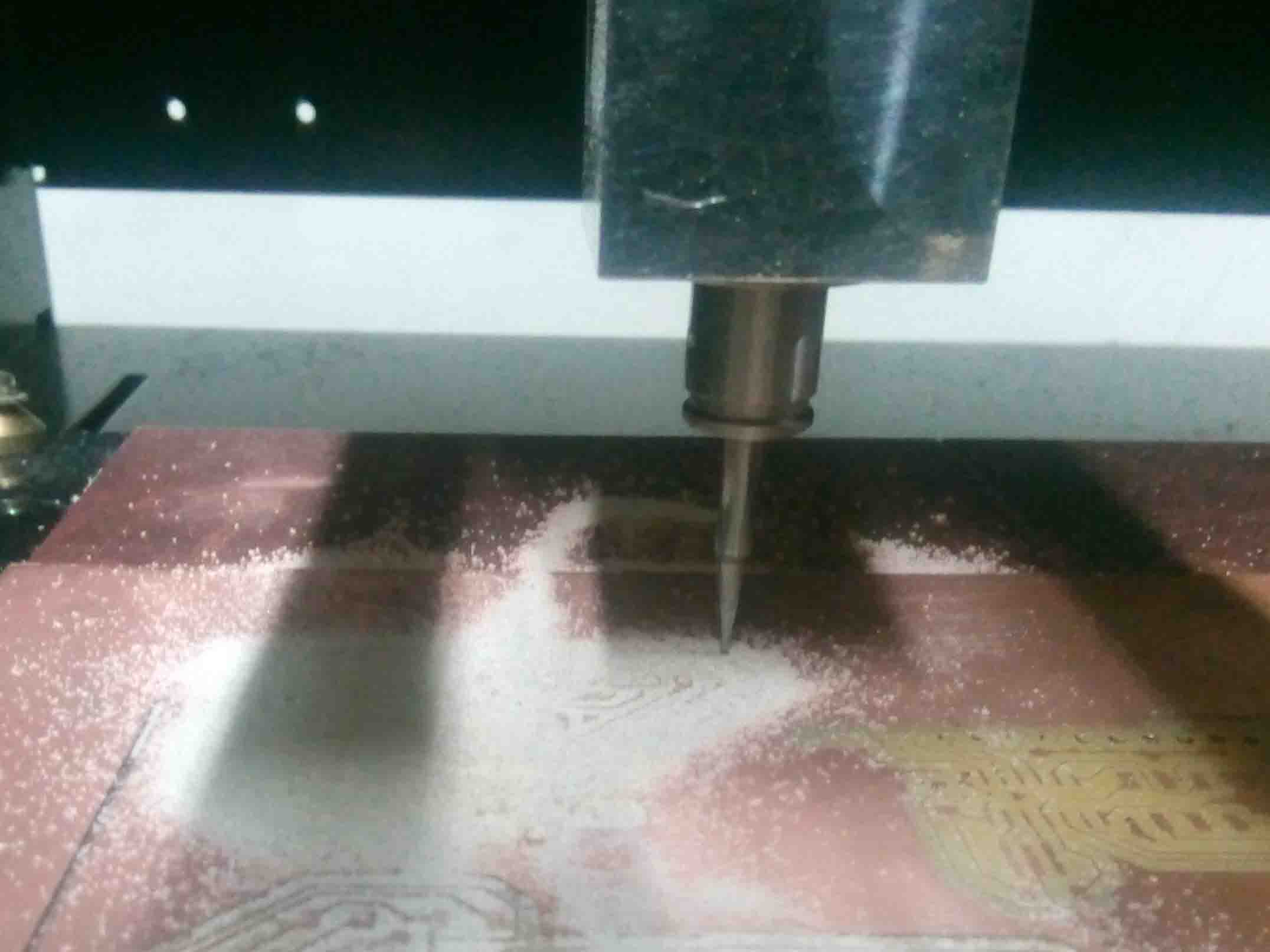
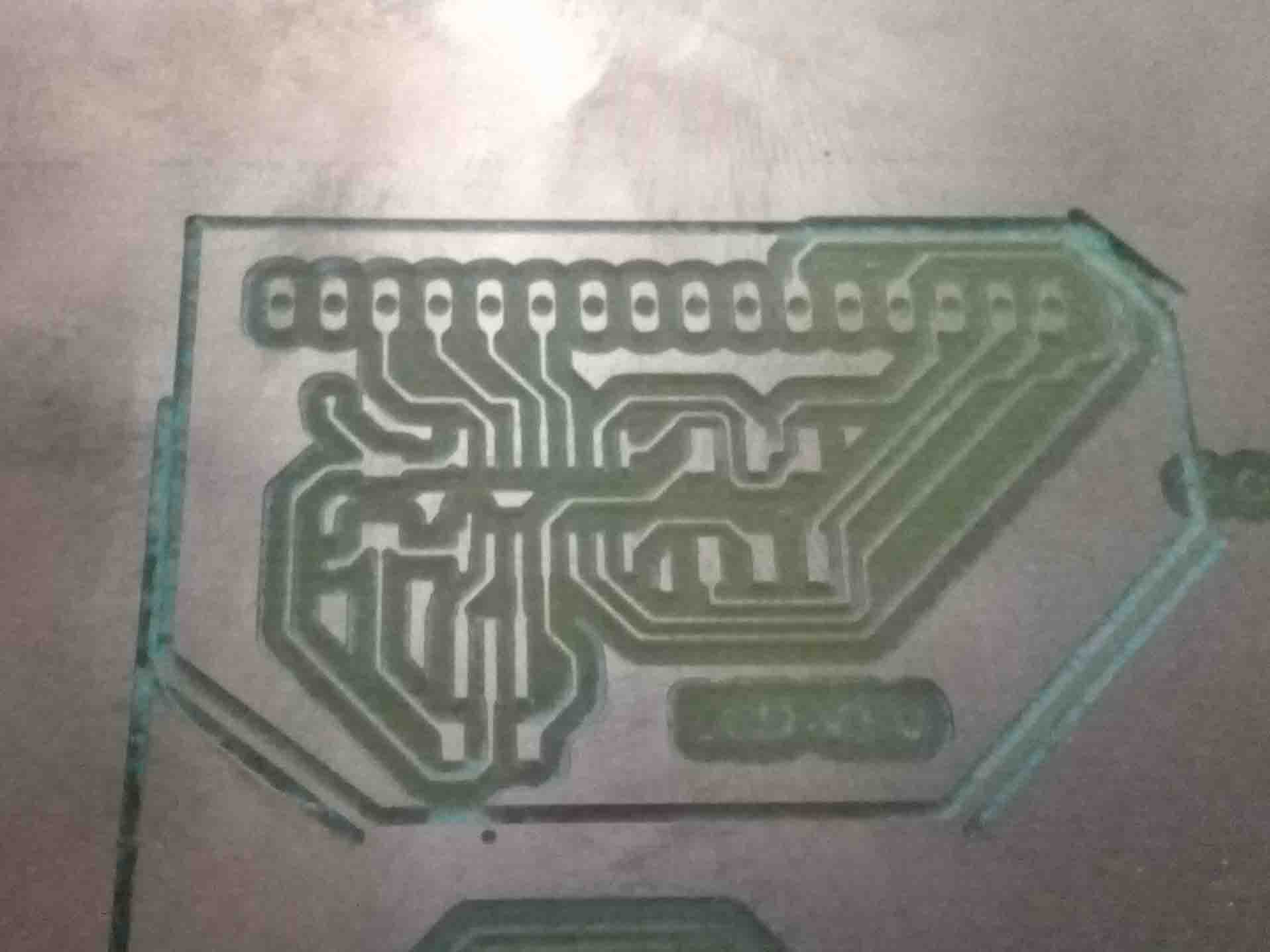
The milling is done and I started drilling the holes for the vias and pads
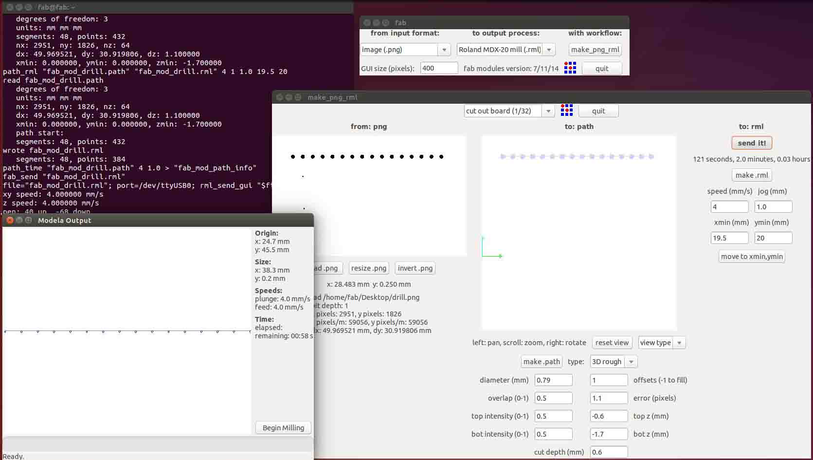
I have used a 1/32 drilling bit for this operation
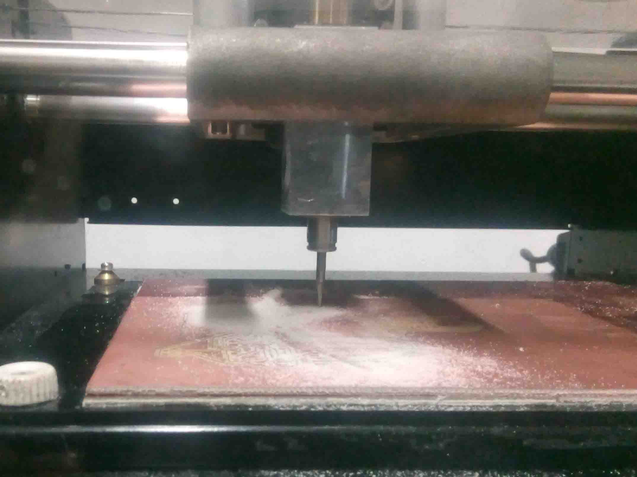
When it's done, I moved for the final cut..
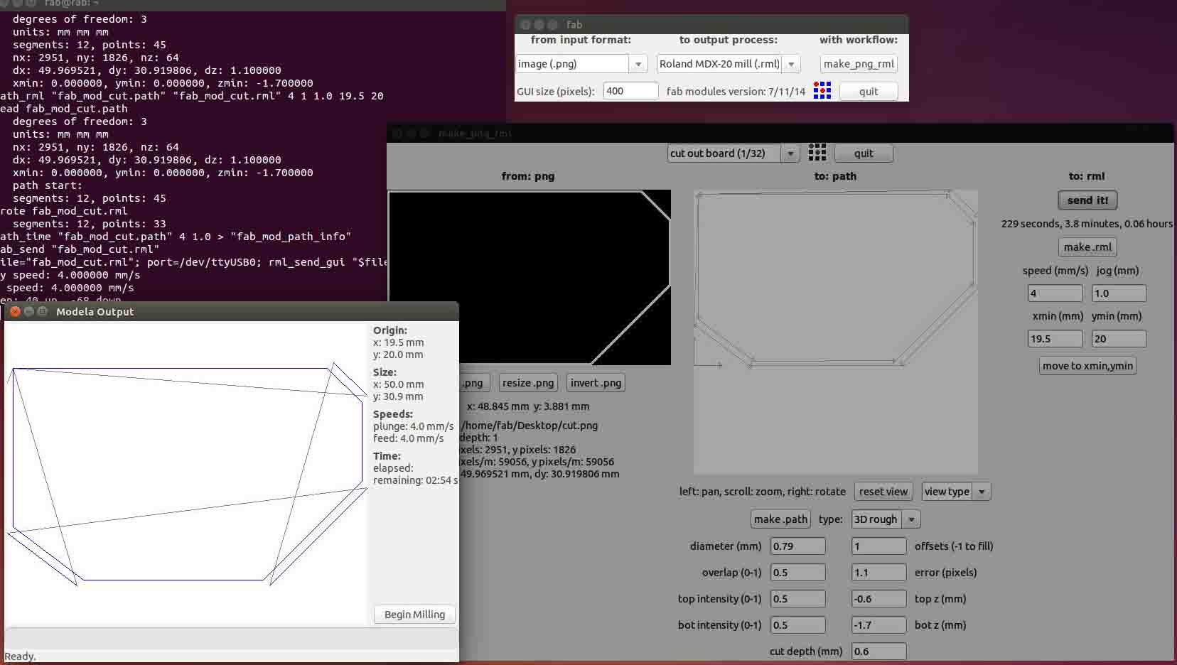
I used the 1/32 inch bit for this operation as well
It finally look like this.
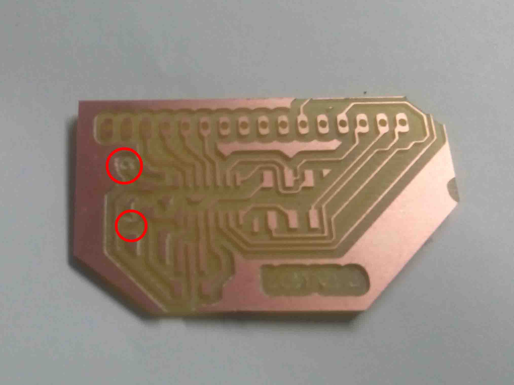
But there was some problems, The vias were too small to be seen by the fab mod. So I had to use a hand drill to make some holes
I have made a list of all the components I needed earlier. All I had to do is to pick them up from the inventory
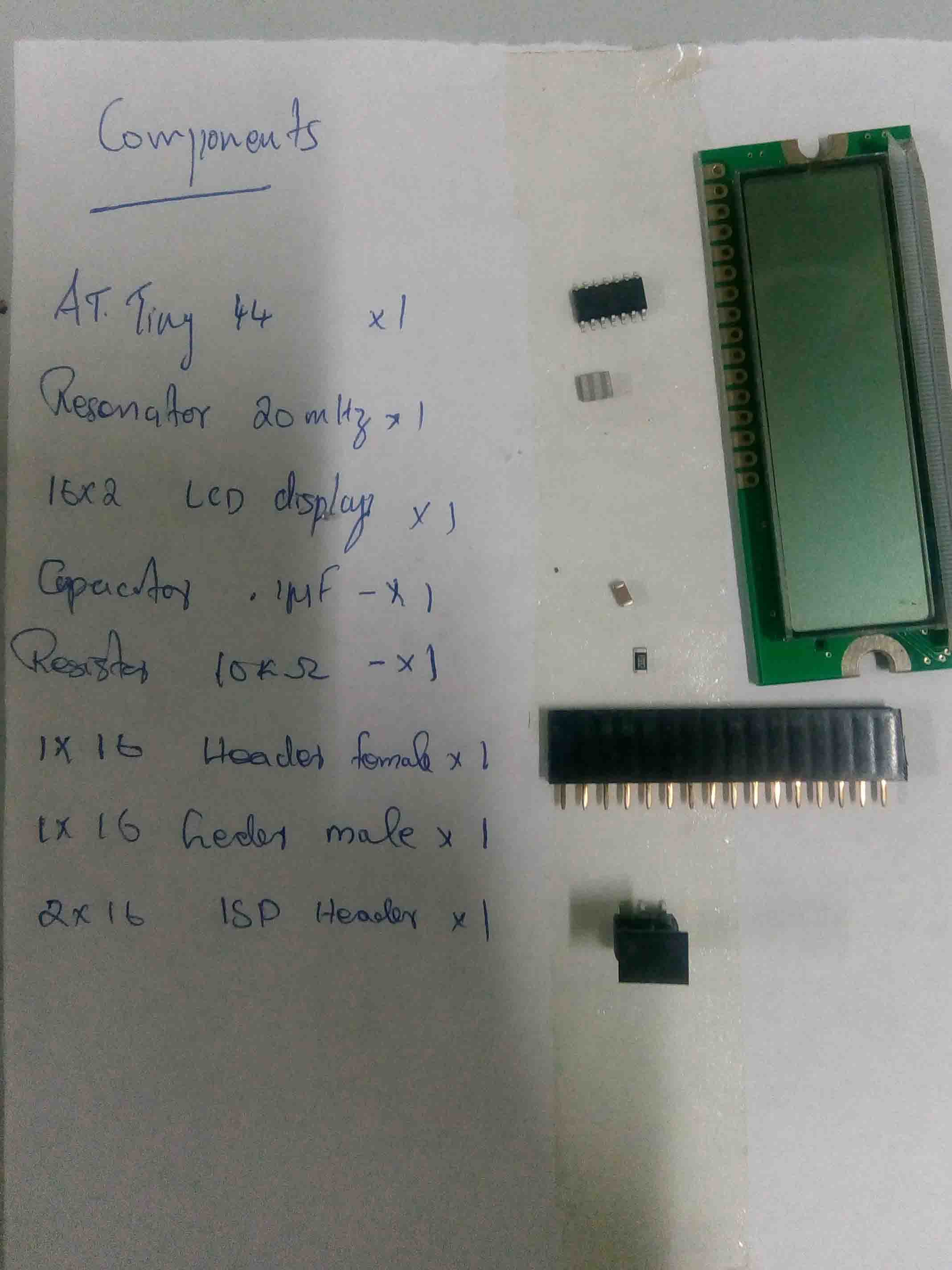
and solder them to the board. But there was a trace which is cut from the board. I added a jimper wire to solve that problem.
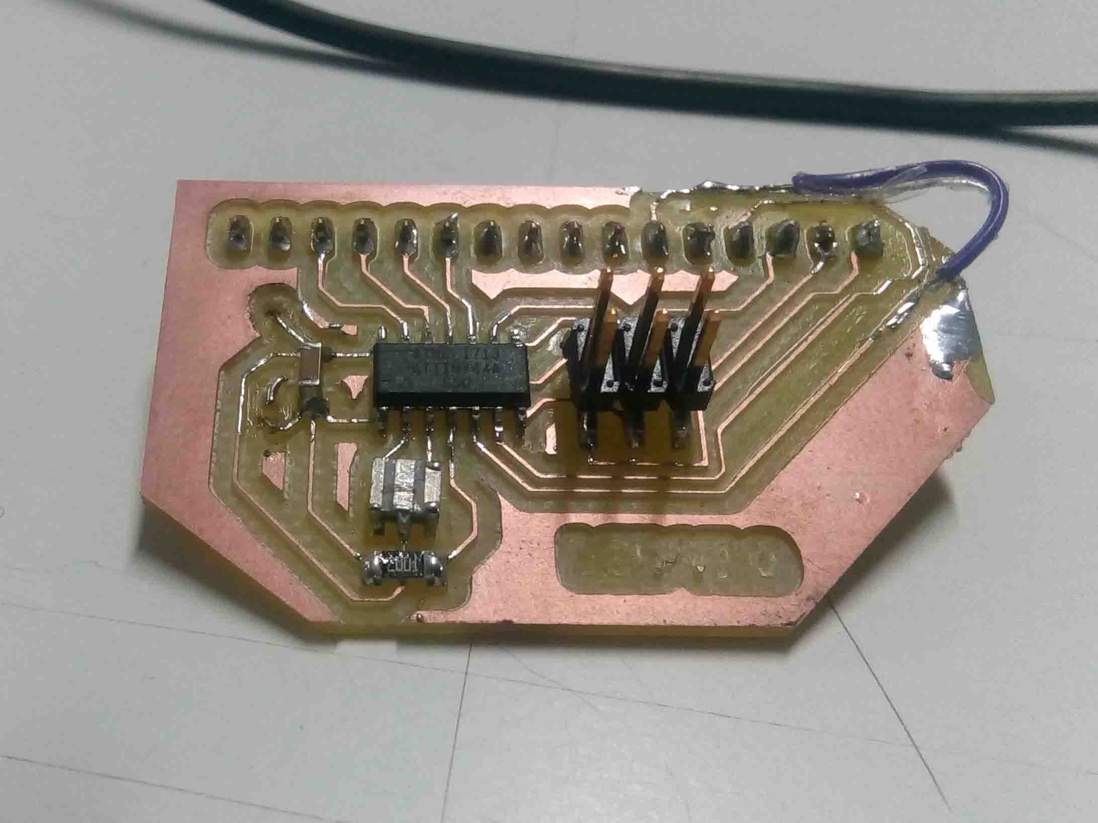
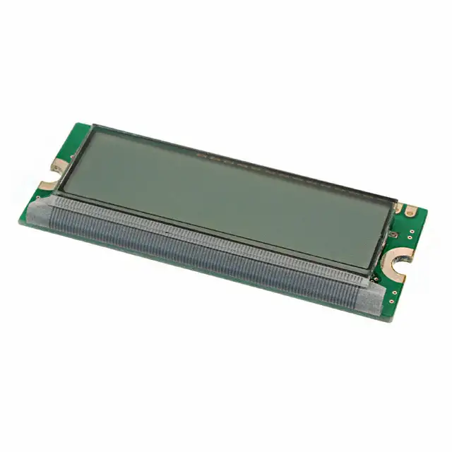
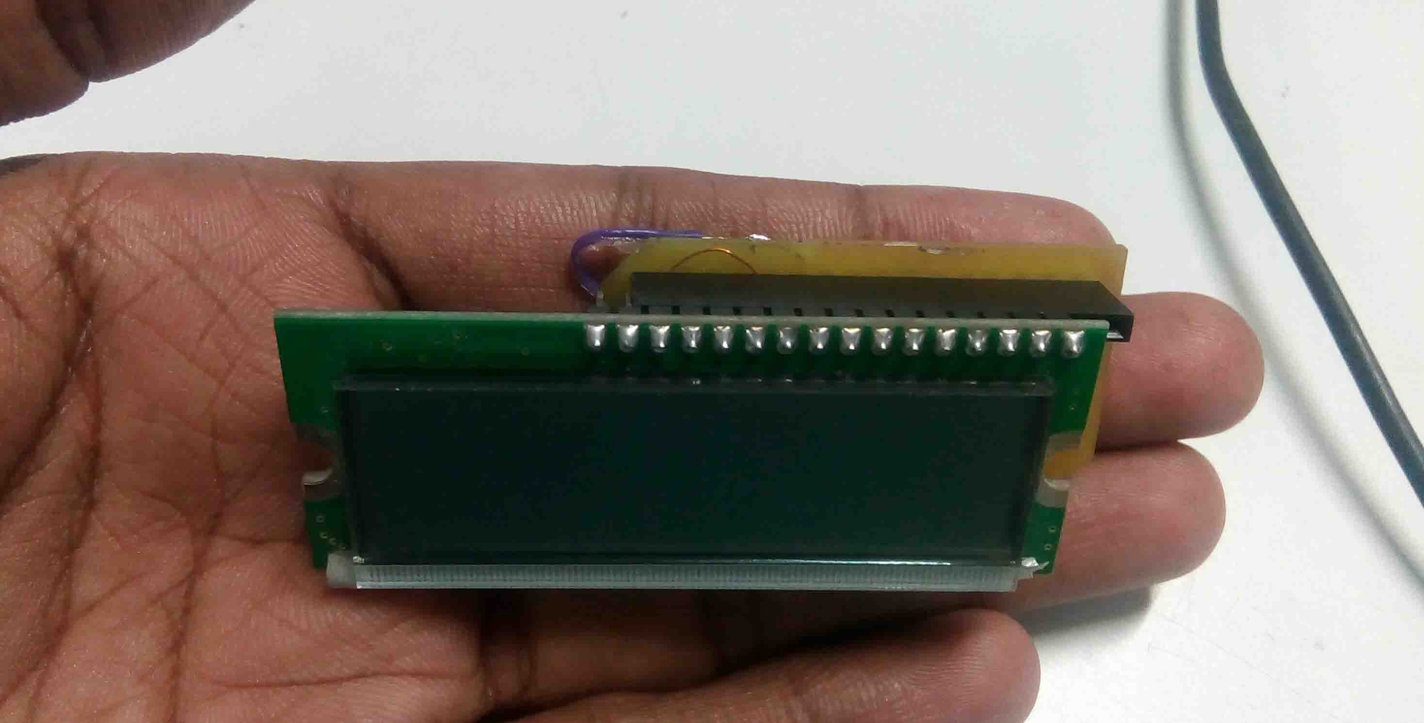
The LCD was a seperate PCB. So I had to add some header to connect to the Attiny controller board.
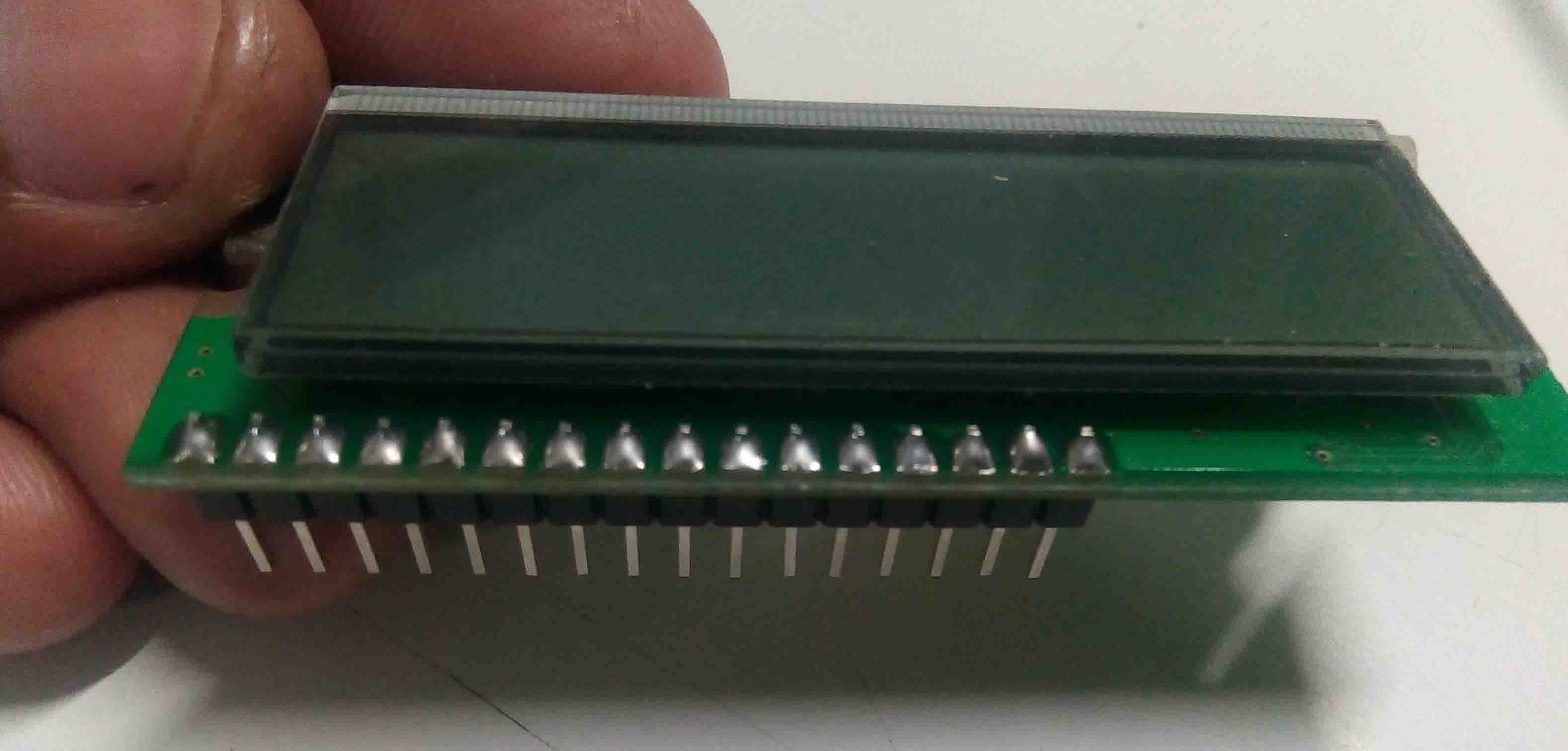
Now I can fit both the board via header pins.
Now I have complete production process. Now It's time to programs the board.
Programming
The prohramming part was very simple. The board was working perfectly. I opened Arduino IDE and entered the following code.
// include the library code:
#include <LiquidCrystal.h>
// initialize the library by associating any needed LCD interface pin
// with the arduino pin number it is connected to
const int rs = 7, en = 8, d4 = 3, d5 = 2, d6 = 1, d7 = 0;
LiquidCrystal lcd(rs, en, d4, d5, d6, d7);
void setup() {
// set up the LCD's number of columns and rows:
lcd.begin(16, 2);
// Print a message to the LCD.
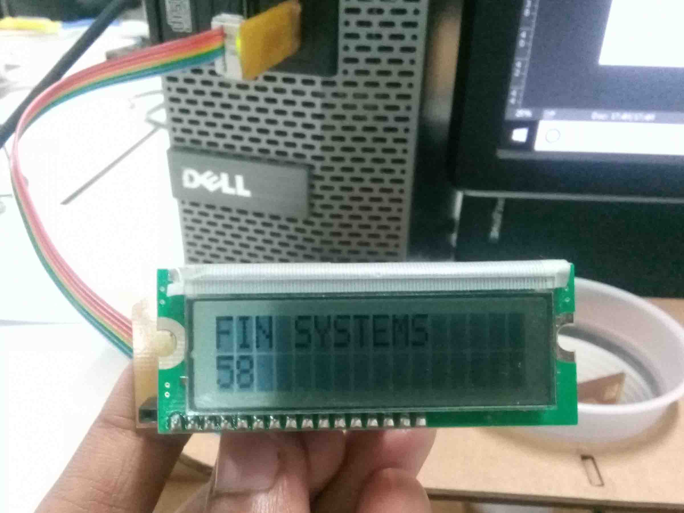
lcd.print("FIN SYSTEMS");
pinMode(4,OUTPUT);
}
void loop() {
analogWrite(4,122);
// set the cursor to column 0, line 1
// (note: line 1 is the second row, since counting begins with 0):
lcd.setCursor(0, 1);
// print the number of seconds since reset:
lcd.print(millis() / 1000);
}
I hooked up the board using FabISP to the computer and burn the code into ATTiNY 44.
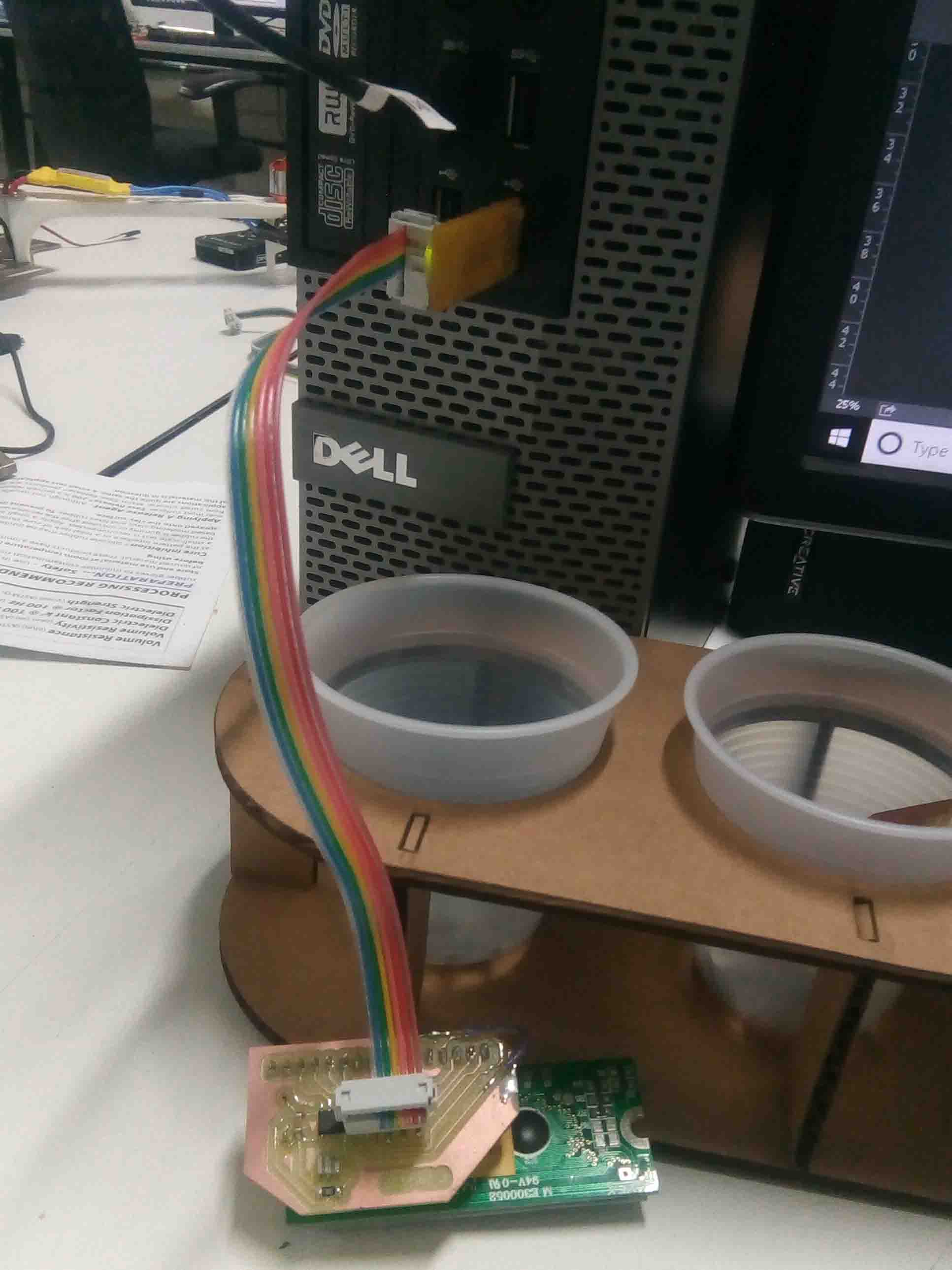
The board worked perfectly and the diplay show what I have entered in the code I uploaded.
Here is the video showing the result..
So that's it for this week.....
Group Assignments
Power (W)
Electric power is the rate, per unit time, at which electrical energy is transferred by an electric circuit. The SI unit of power is the watt (W), one joule per second. For calculating the consumed power, We must know it's
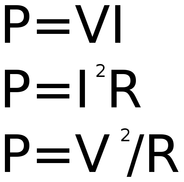
Here is the equation for calculating Power..
Mesuring Power
As you can see in the above equation, we need to find out the variables. For that we need to test for following using a multimeter
Voltage
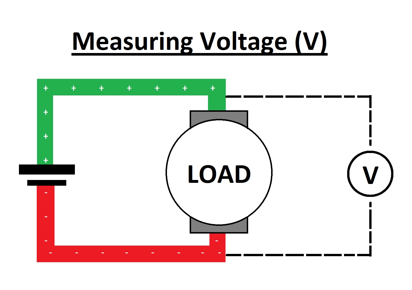
>The voltage is calculated by connecting parallel to the "Load". Here Units of Voltage is "Volt(V)"
Current
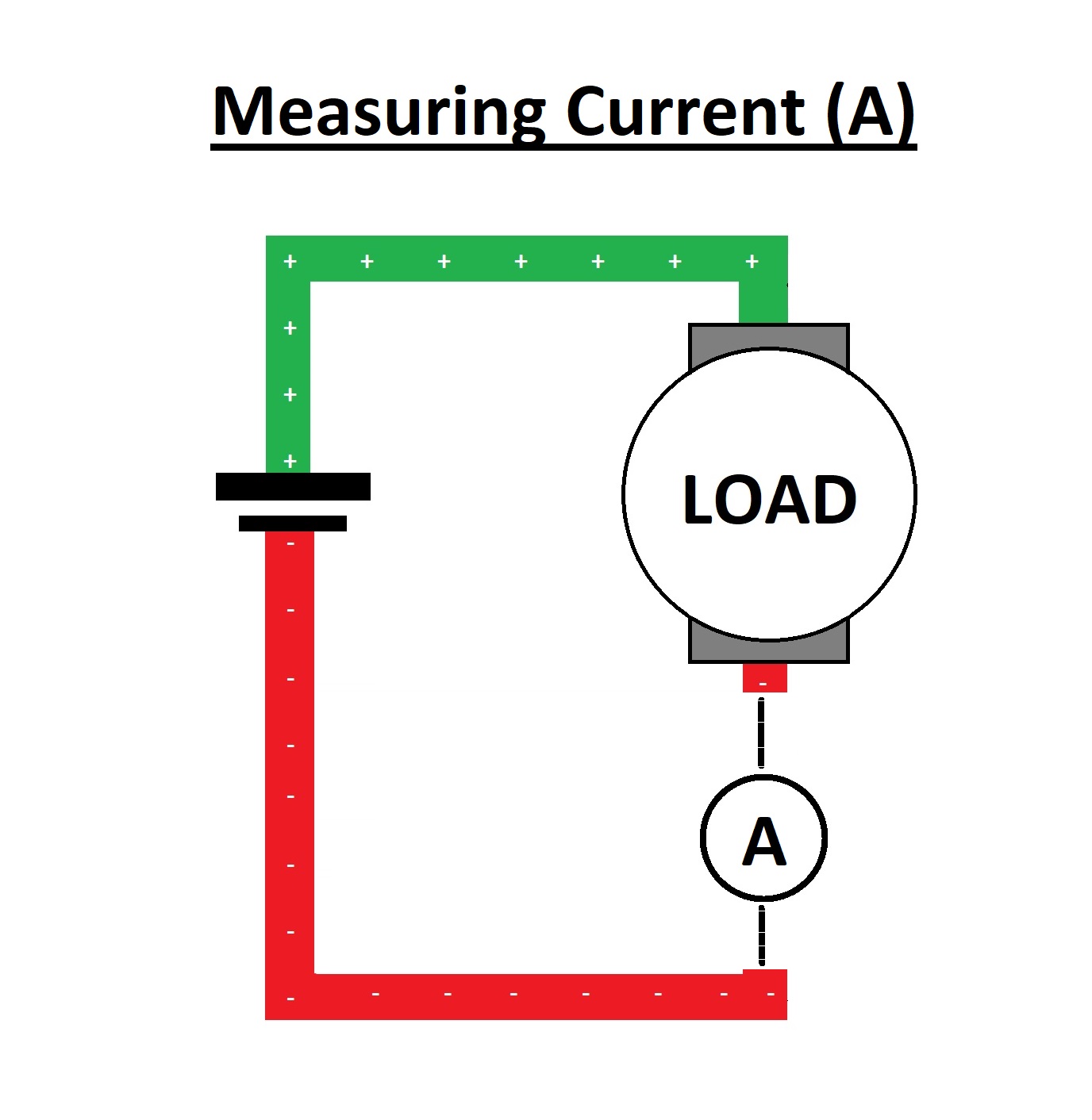
The Current is calculated by connecting series to the "Load".Here Units of Current is "Ampere(A)"
Resistance
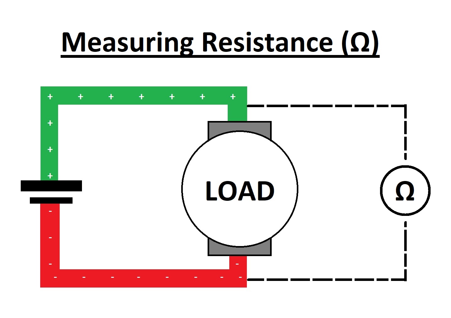
The Resistance is calculated by connecting parallel to the "Load"Here Units of Resistance is "Ohm(Ω)"
So we used a multimeter to find out the variables..
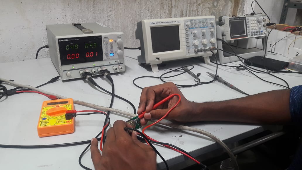
So here we got:
So power can be calculated as:

Substitute values in the equation:
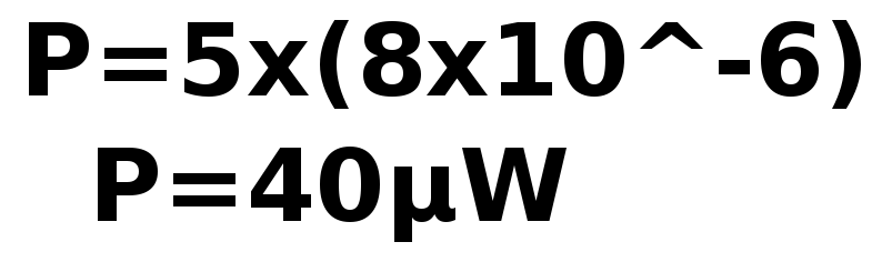
So the power of the output device is "40μW".
By repeating the process and we can find other output devices power consumption...