
Wild Card
Introduction
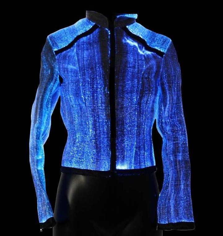
This week assignment is to make something new. I know, every week we do new things, But in this week i can do anything. The only pre requestment is Design and produce something with a digital fabrication process (incorporating computer-aided design and manufacturing) not covered in another assignment, documenting the requirements that your assignment meets, and including everything necessary to reproduce it. So i decided to make a E-textile. My plan is glow few LEDs that placed around the neck of a Tshirt . I decided to make a flexible PCB that can atach to any tshirt. Through this way, i can use them in any tshirt and also i can remove them while washing the Tshirt.
E-Textiles
LEDs and fiber optics as part of fashion Electronic textiles, also known as smart garments, smart clothing, smart textiles, or smart fabrics, are fabrics that enable digital components such as a battery and a light (including small computers), and electronics to be embedded in them. Smart textiles are fabrics that have been developed with new technologies that provide added value to the wearer. Pailes-Friedman of the Pratt Institute states that "what makes smart fabrics revolutionary is that they have the ability to do many things that traditional fabrics cannot, including communicate, transform, conduct energy and even grow. Learn more
Adafruit neopixel LEDs
hear i use neopixel LEDs.These LED strips are even more fun and glowy. you can control each LED individually! Yes, that's right, this is the digitally-addressable type of LED strip. You can set the color of each LED's red, green and blue component with 8-bit PWM precision (so 24-bit color per pixel). The LEDs are controlled by shift-registers that are chained up down the strip so you can shorten or lengthen the strip. Only 1 digital output pin are required to send data down. The PWM is built into each LED-chip so once you set the color you can stop talking to the strip and it will continue to PWM all the LEDs for you
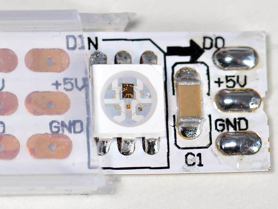
So in case you haven’t heard yet, digital LEDs are the go-to solution for any project that uses RGB LEDs and you want to avoid the rat's nest that ensures when using multiple RGB LEDs, each colour requiring its own connection. Digitally addressable LEDs allow you to control large numbers of LEDs using digital communication to tiny onboard chips integrated into the LEDs which read these digital commands and do all the heavy lifting for you. The go to LED chip for these purposes has been the WS2812 which you might know most prominently as Adafruit’s NeoPixels. The WS2812B LEDs have been around for a few years now, and come in two different flavours, WS2812 and WS2812B. Both operate similarly, however, require slightly different timing according to the datasheet. There are also other chips which power NeoPixel branded LEDs that work in the exact same way, with the same code and are the drop-in replacement, however, the WS2812 line is the most common.
Schematics and PCB design.
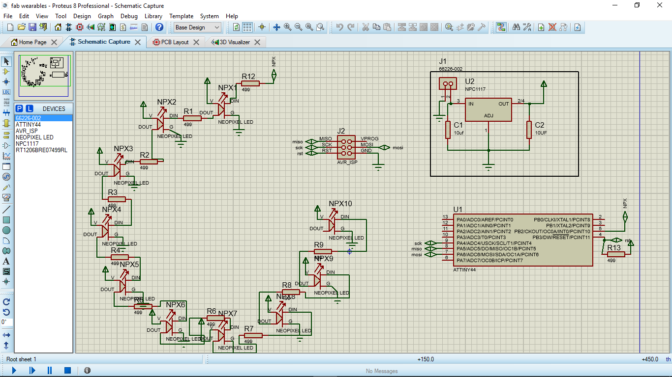
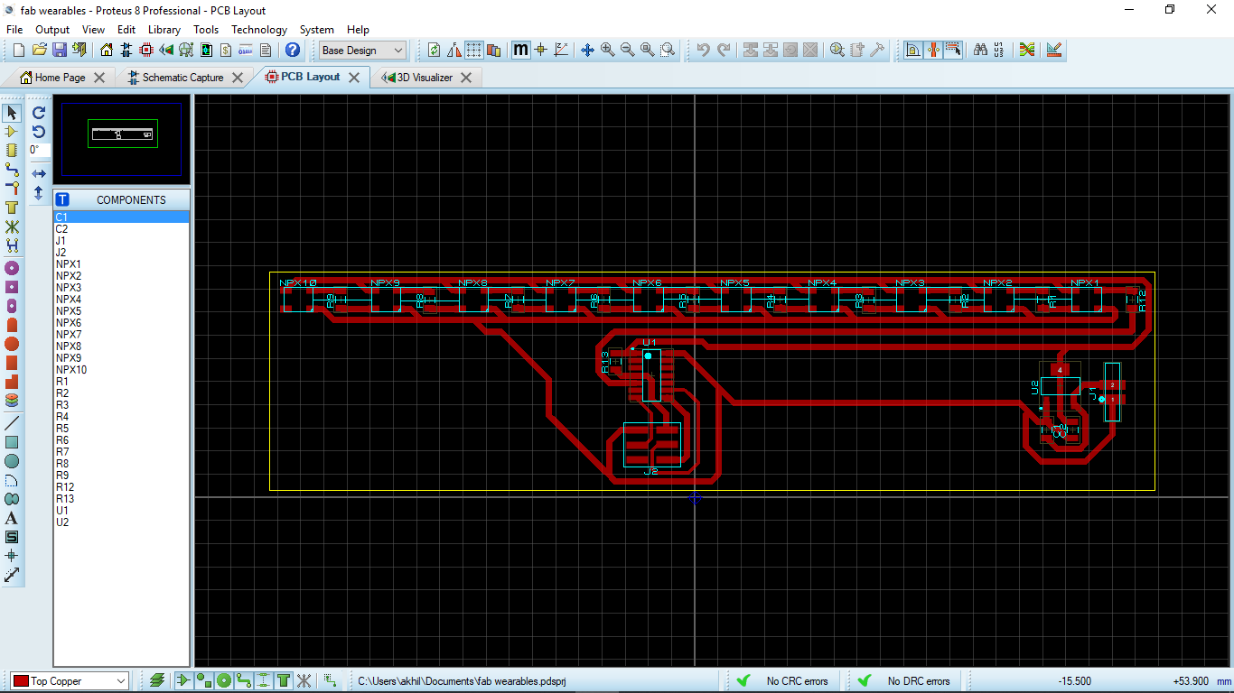
First i need to design the schematics. I started designing the schematics using proteus PCB. I used a Attiny44 Microcontroller. I have enough pins to conect all my LEDs and the sensor. I used NEOPIXEL LEDs. Its multi color LEDs and also can be addressable. So i need jst one pin to control full LEDs. i use 10 LEDs.I removed the ISP programing head because i just program them once. so i decided to remove them to avoide complexity in routing. I placed a 2x2 pin header to power the board externaly from a battery.
Download PCB design files
Making the Flexible PCB
Now i need to make the flexible PCB. I decided to build one in my own way. To make a flexingle PCB, I decided to choose chemical eching using Ferric Chloride(FeCl3). I choose a OHP sheet as the base material for the PCB. Above of the vynyl sheet i stacked a copper tap sheet.
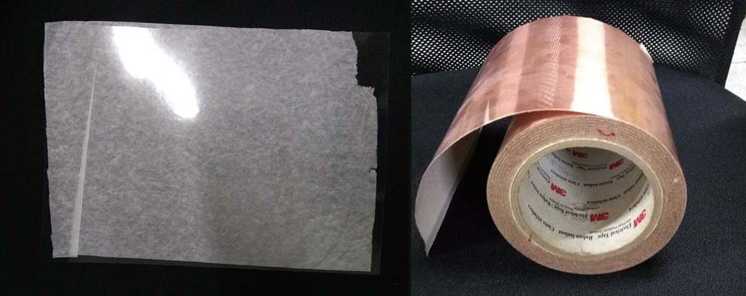
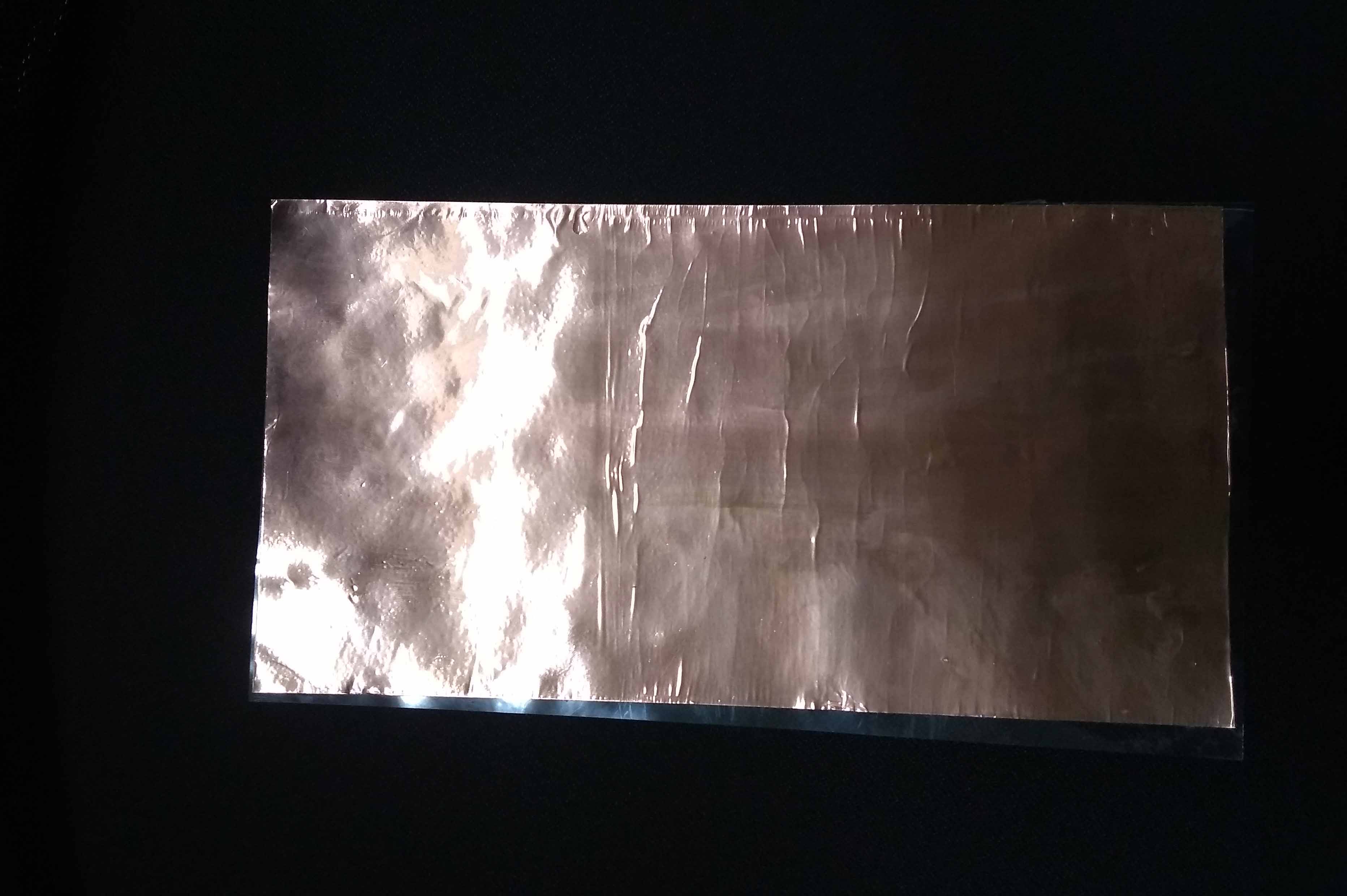
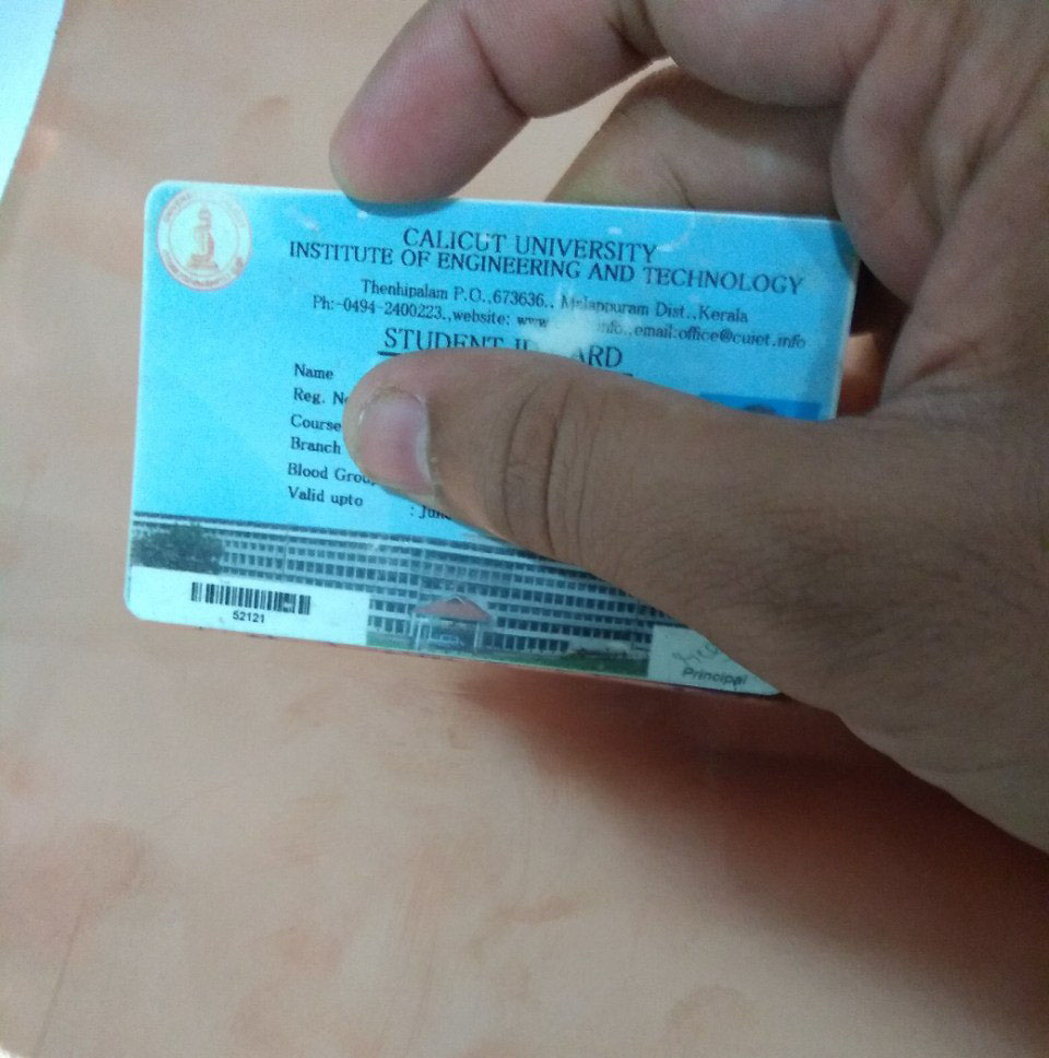
I removed the small bubbles traped inside the copper tap while placing the sheets together using a credit card.
Now the PCB board is ready but i need to make the design on the PCB. There are many ways to do that. I always choose milling the PCB using a PCB milling machine. I can also use vinyl cutter. So idecided to do in vinyl cutter machine.
Cut out PCB design using Vinyl cutter
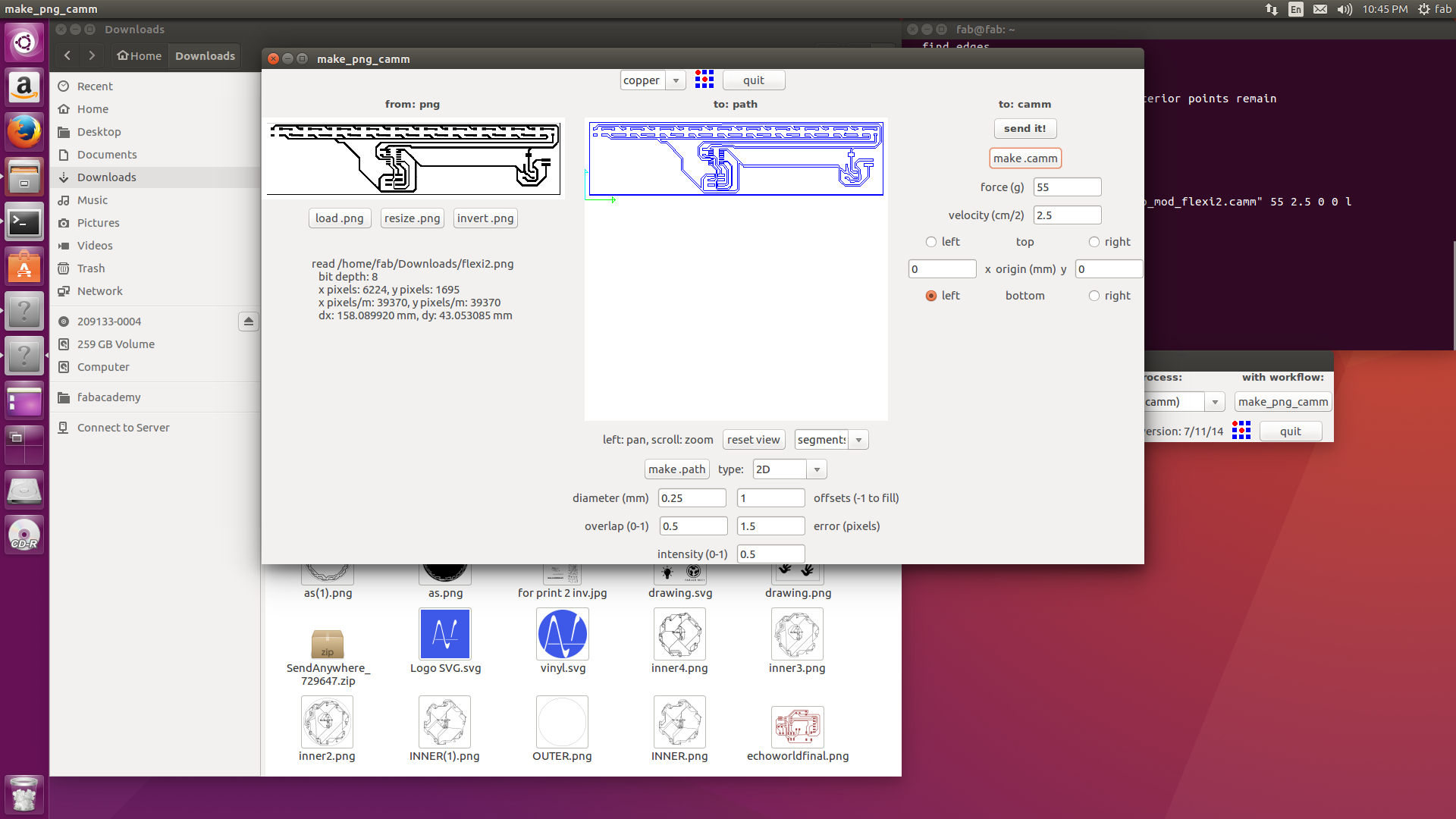
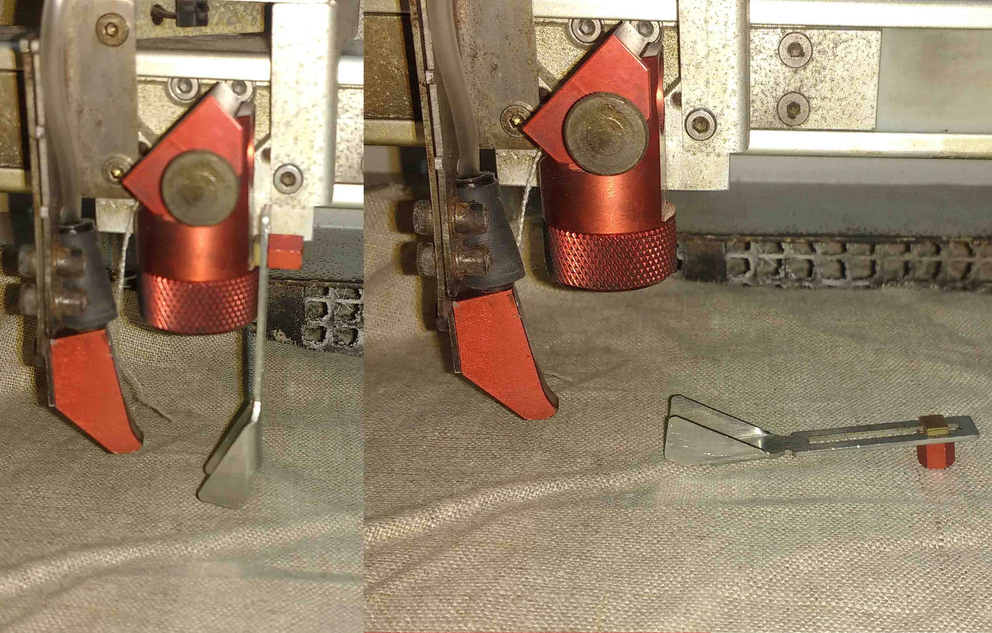
I placed the PCB sheet that i previously made in the vinyl cutter. After that opened the Fab modules and selected Roland vinyl cutter as machine. I loaded the png image file of my PCB design. I Selected Copper sheet as the material. i adjusted the force to 0. The machine started cutout the PCB.
After cutting out the PCB. I carefully removed the unwanted copper tapes from the sheet. There is high chance to rip the traces too, so i used a tweezer to remove the copper. Then i solder the components
Programming the board
Now i need to program the board to blink the LEDs. I wrote the code in arduino IDE. I does not gave a AVRISP pin header in my board because i just need only to program once and It is too difficult to route the traces. How ever i uploaded the code into the Attiny44 by directly taking wires from the programming pins (MISO,MOSI,SCK,RST,VCC,GND). If you dont know how to program Attiny microcontrollers using arduino please reffer my Embedded programming week
  #include <Adafruit_NeoPixel.h>

  #define LED_PIN    6

  #define LED_COUNT 10

  Adafruit_NeoPixel strip(LED_COUNT, LED_PIN, NEO_GRB + NEO_KHZ800);

  void setup() {
  #if defined(__AVR_ATtiny85__) && (F_CPU == 16000000)
    clock_prescale_set(clock_div_1);
  #endif
    strip.begin();
    strip.show();
    strip.setBrightness(50);
  }


  void loop() {
    colorWipe(strip.Color(255,   0,   0), 50);
    colorWipe(strip.Color(  0, 255,   0), 50);
    colorWipe(strip.Color(  0,   0, 255), 50);

    theaterChase(strip.Color(127, 127, 127), 50);
    theaterChase(strip.Color(127,   0,   0), 50);
    theaterChase(strip.Color(  0,   0, 127), 50);

    rainbow(10);
    theaterChaseRainbow(50);
  }

  void colorWipe(uint32_t color, int wait) {
    for (int i = 0; i < strip.numPixels(); i++) {
      strip.setPixelColor(i, color);
      strip.show();
      delay(wait);
    }

    void theaterChase(uint32_t color, int wait) {
      for (int a = 0; a < 10; a++) {
        for (int b = 0; b < 3; b++) {
          strip.clear();
          for (int c = b; c < strip.numPixels(); c += 3) {
            strip.setPixelColor(c, color);
          }
          strip.show();
          delay(wait);
        }
      }
    }

    void rainbow(int wait) {

      for (long firstPixelHue = 0; firstPixelHue < 5 * 65536; firstPixelHue += 256) {
        for (int i = 0; i < strip.numPixels(); i++) { // For each pixel in strip...
          int pixelHue = firstPixelHue + (i * 65536L / strip.numPixels());
          strip.setPixelColor(i, strip.gamma32(strip.ColorHSV(pixelHue)));
        }
        strip.show();
        delay(wait);
      }
    }


    void theaterChaseRainbow(int wait) {
      int firstPixelHue = 0;
      for (int a = 0; a < 30; a++) {
        strip.clear();
        for (int c = b; c < strip.numPixels(); c += 3) {
          int      hue   = firstPixelHue + c * 65536L / strip.numPixels();
          uint32_t color = strip.gamma32(strip.ColorHSV(hue));
          strip.setPixelColor(c, color);
        }
        strip.show();
        delay(wait);
        firstPixelHue += 65536 / 90;
      }
    }
  }
Download Arduino code
Stiching the LED
Herare i use velcro, to fix board in the board, its a paire of cloths used to fix each other.
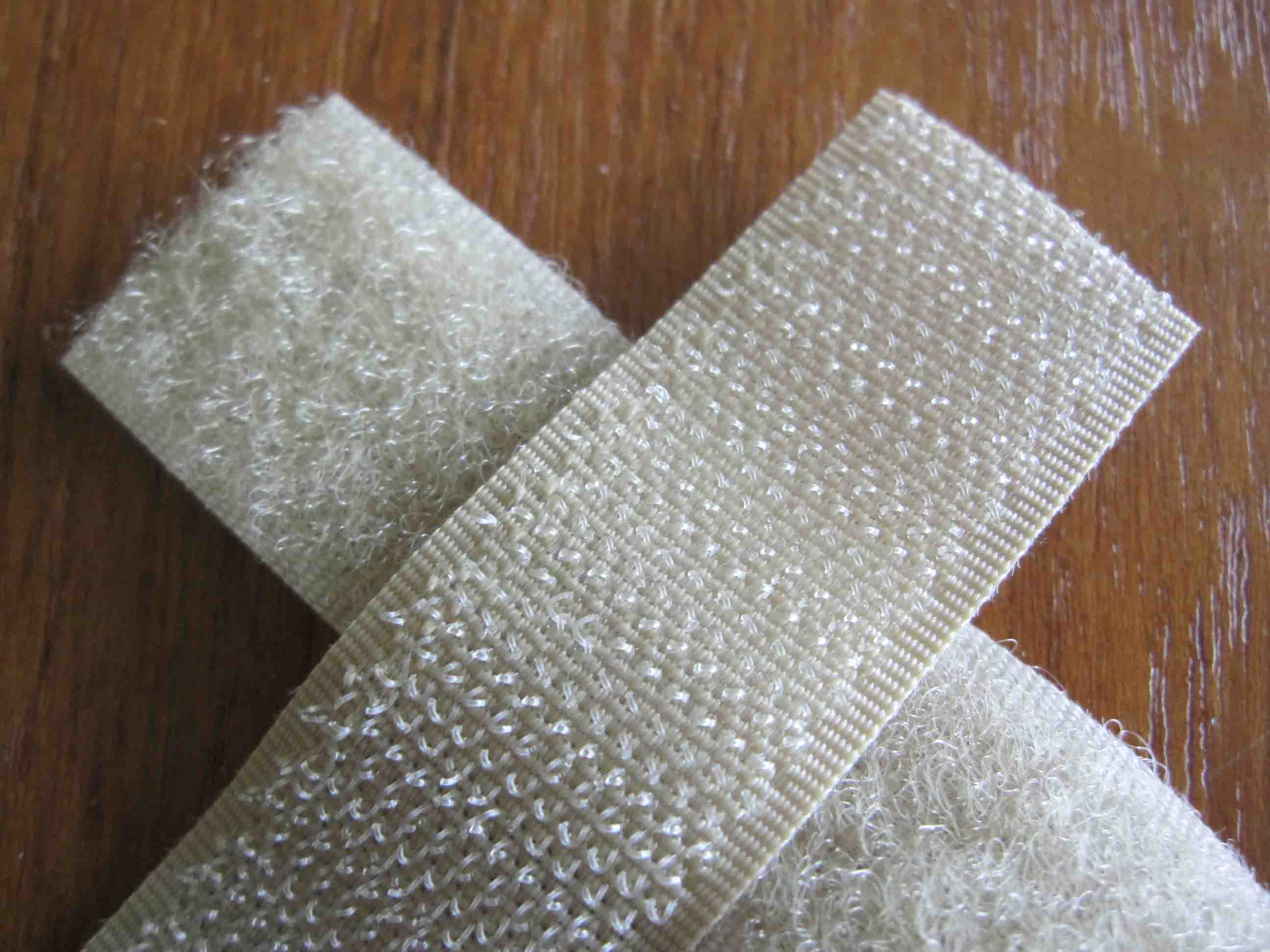
I fix Hook on board and Loop in my T-shirt. This will help to remve this as i wish, (for washing)
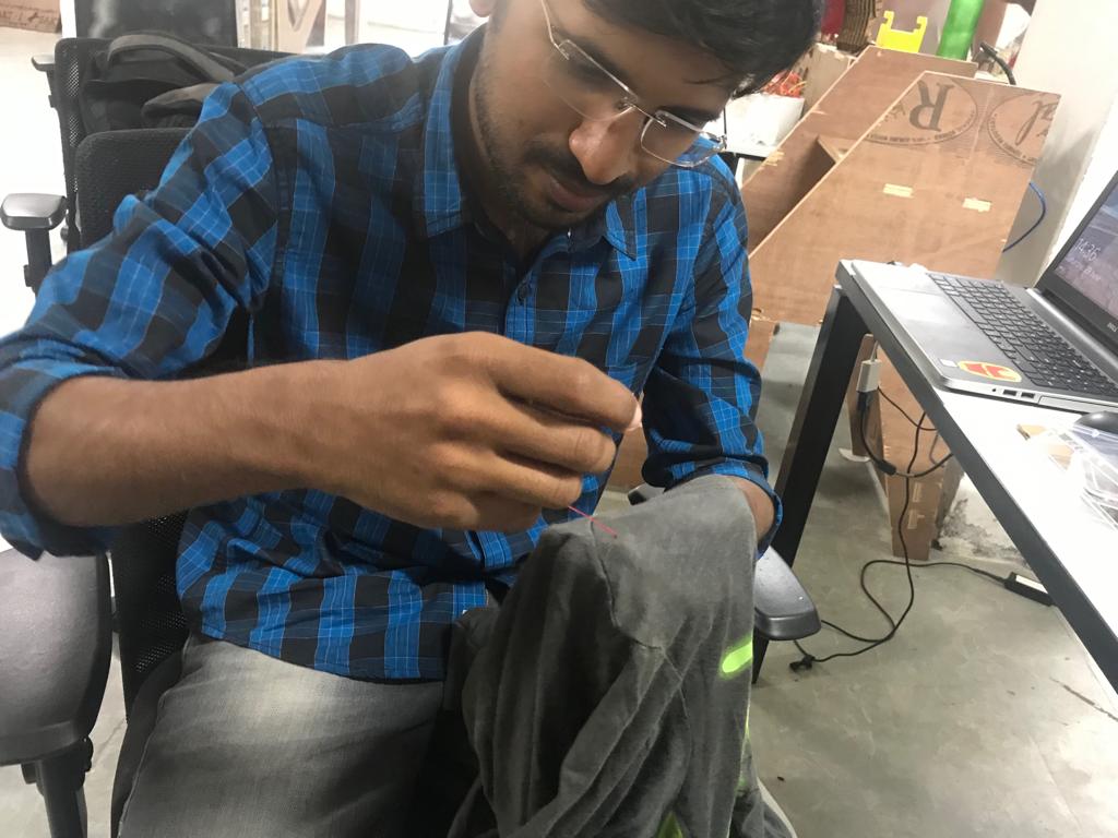
stiching is littile bit duifficult for me, my mother help to learn this, i m 1st ime to stiching.
E-Tshirt Demo
Composit
A composite material (also called a composition material or shortened to composite, which is the common name) is a material made from two or more constituent materials with significantly different physical or chemical properties that, when combined, produce a material with characteristics different from the individual components. The individual components remain separate and distinct within the finished structure, differentiating composites from mixtures and solid solutions.
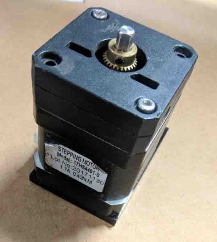
After completing my wearable work my global instructure ask me to make something whith digitalfabricattion So i deside to make a cover for my costom mde 3d-printer extruder. To reduce dust entering to the gear.
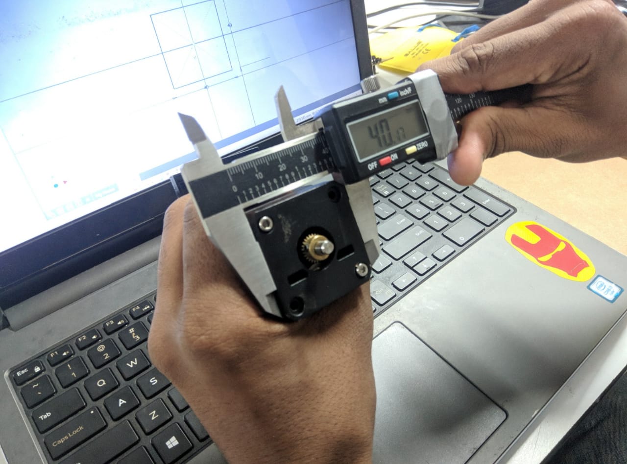
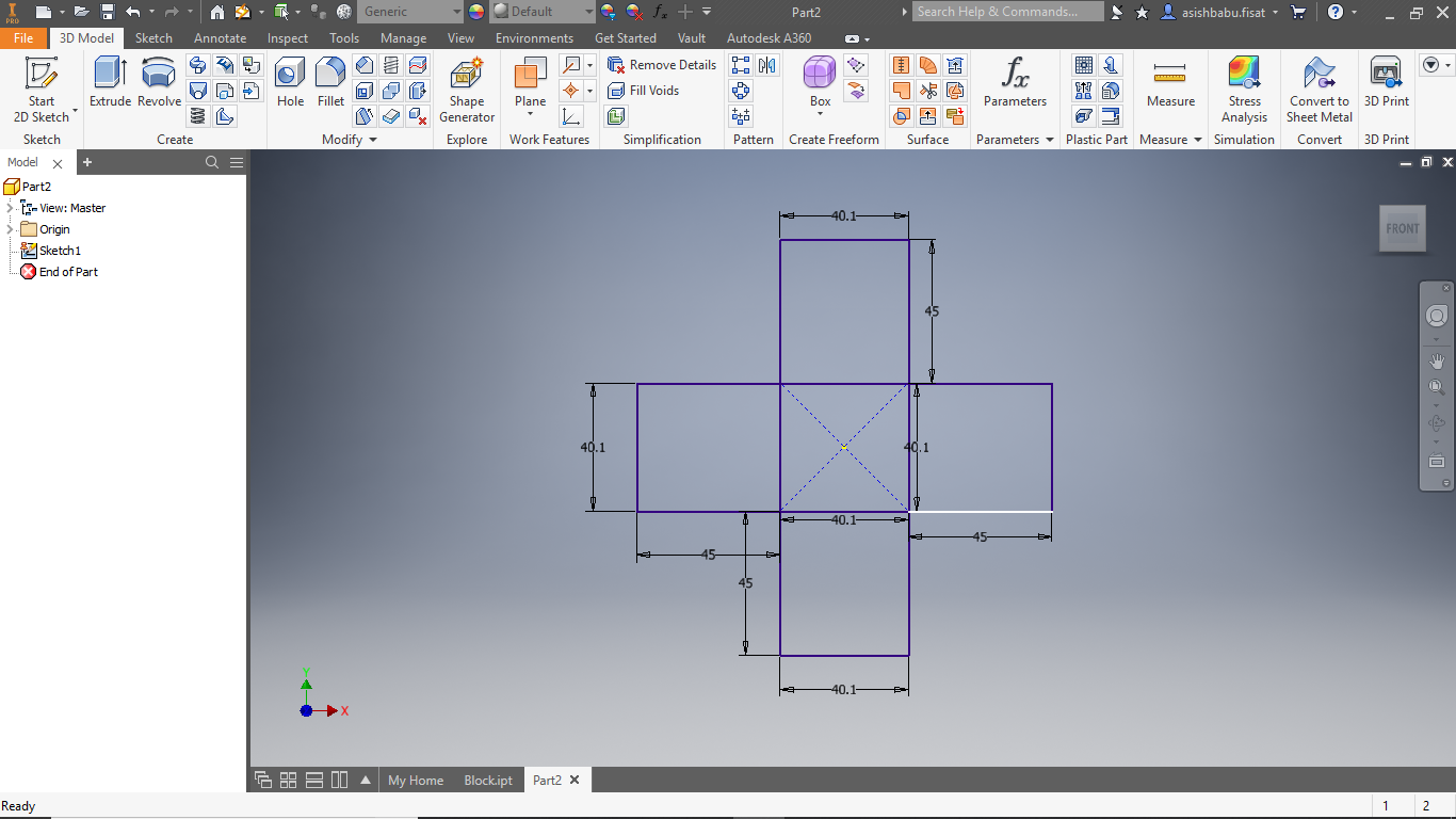
To do this i take the outer dimensions of the extruder. Then i designed it with inventor.
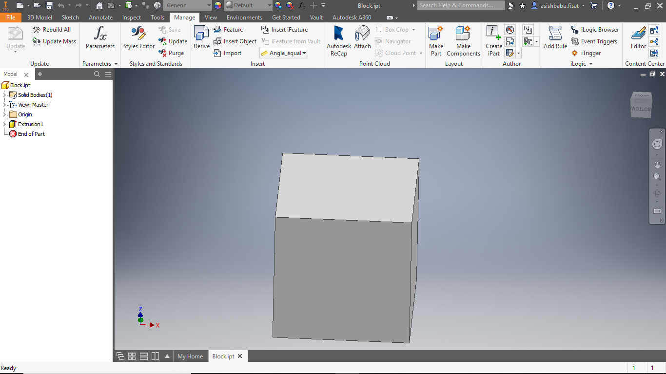
Then i make the design in Autodesk inventor
The i cut in thermocall by shop boat. The thermocal cant screw in shopboat bed, so i stick it on bed using a doublesided tape. Then we need ro set origin,z-axis setting, toolpath generation ..etc
when generate toolpath, try to select OUTSIDE CUT for our required dimensions.
otherwise we will face a difference due to bit diameter
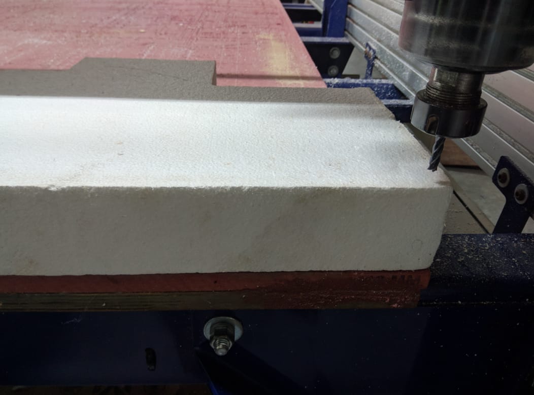
To know how to use shopboat, please refer my computer controled machining week
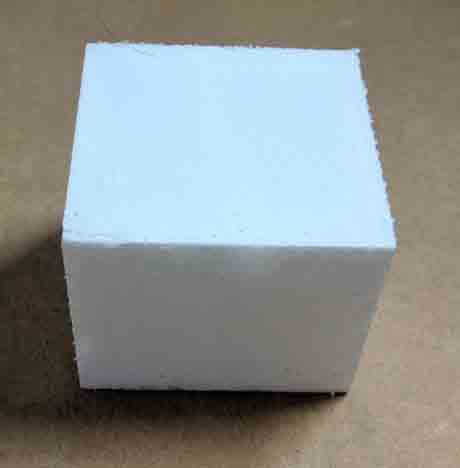
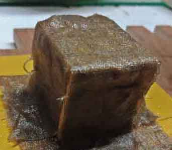
After milling, we got a finished block of thermocall with our measured dimensions.
Material used
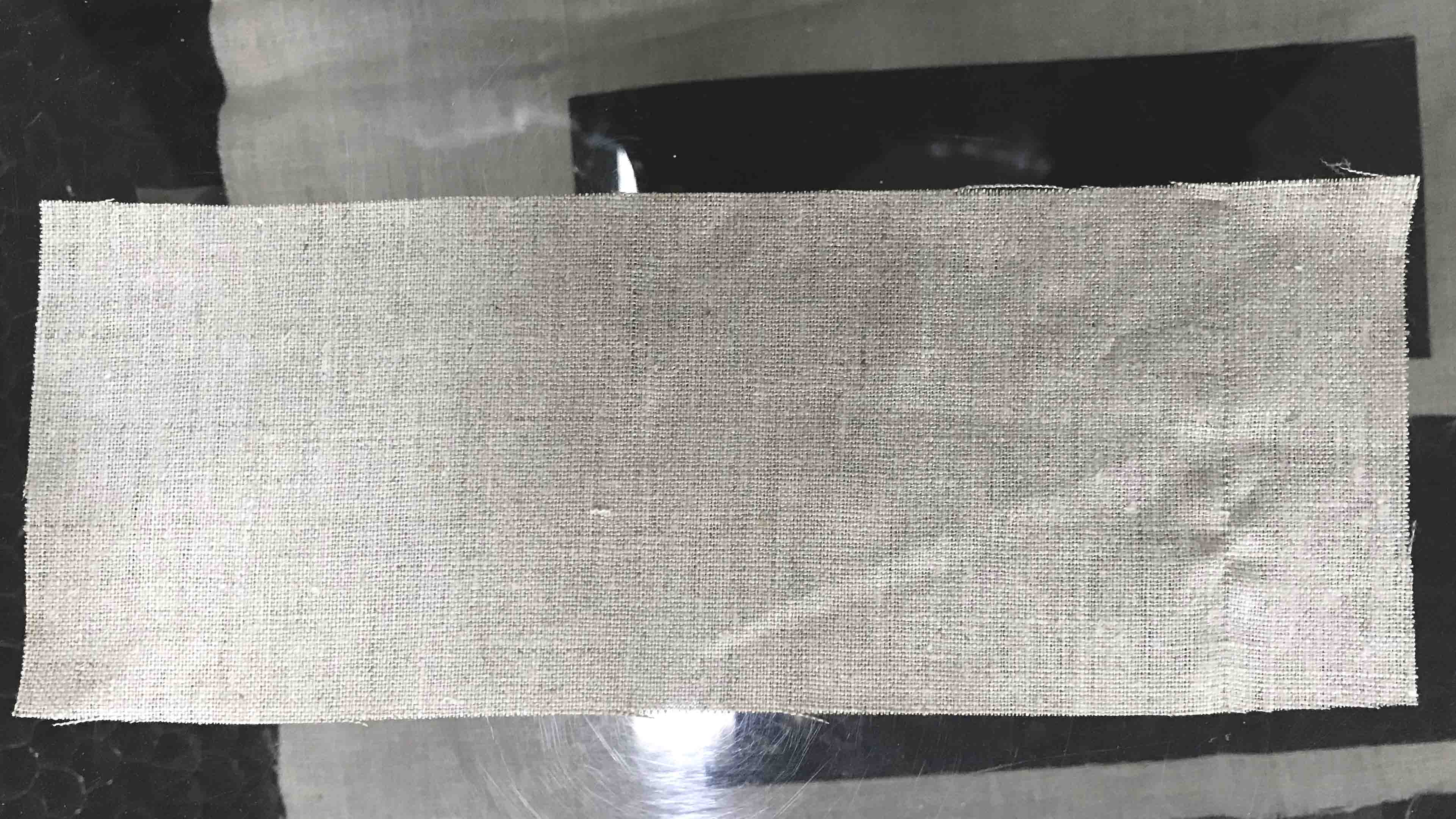
Linen fabricis used as composite
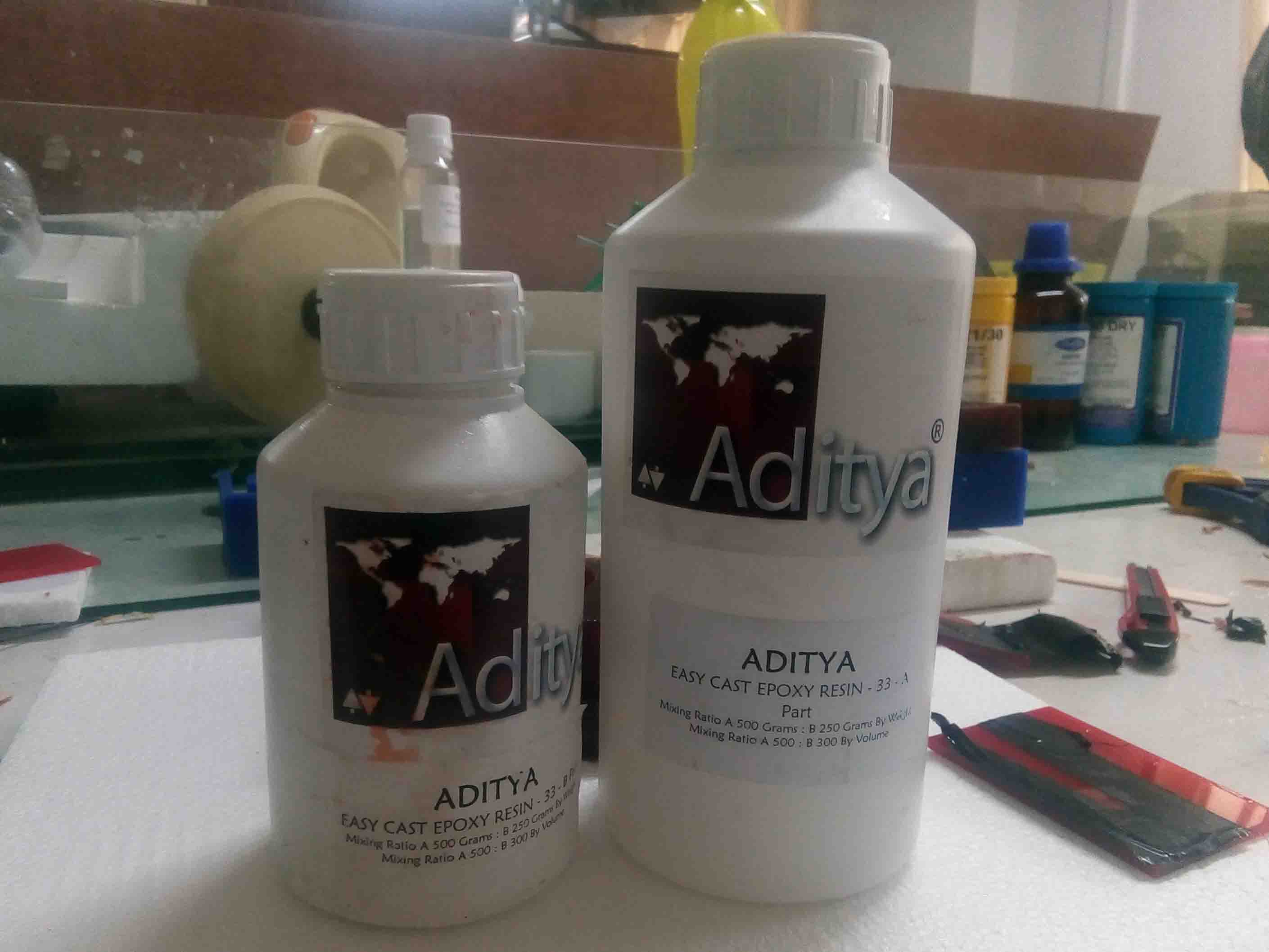
Epoxy resin is used for making the composite . The ratio is 1:2 by weight or 2:3 by volume
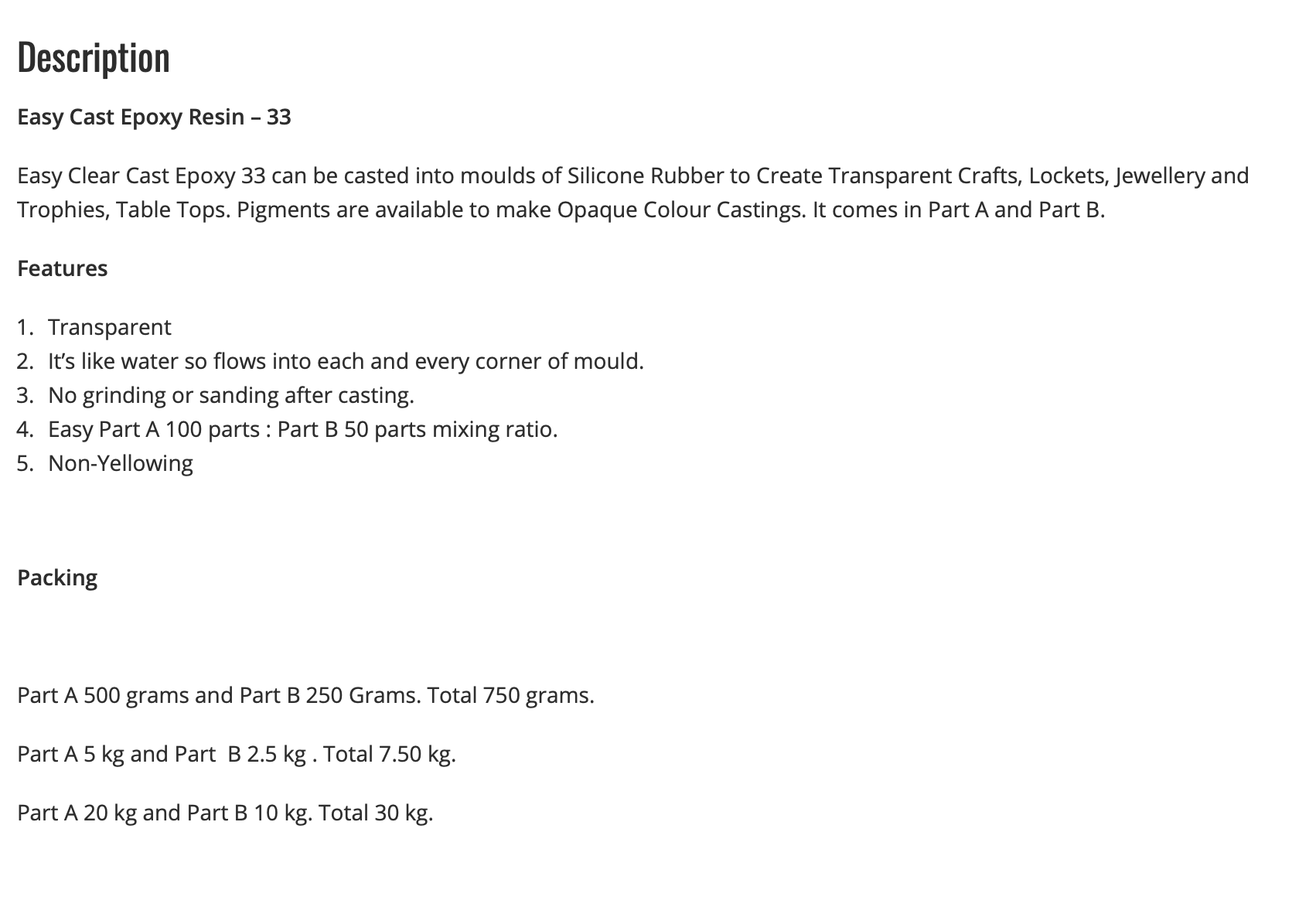
resine Description
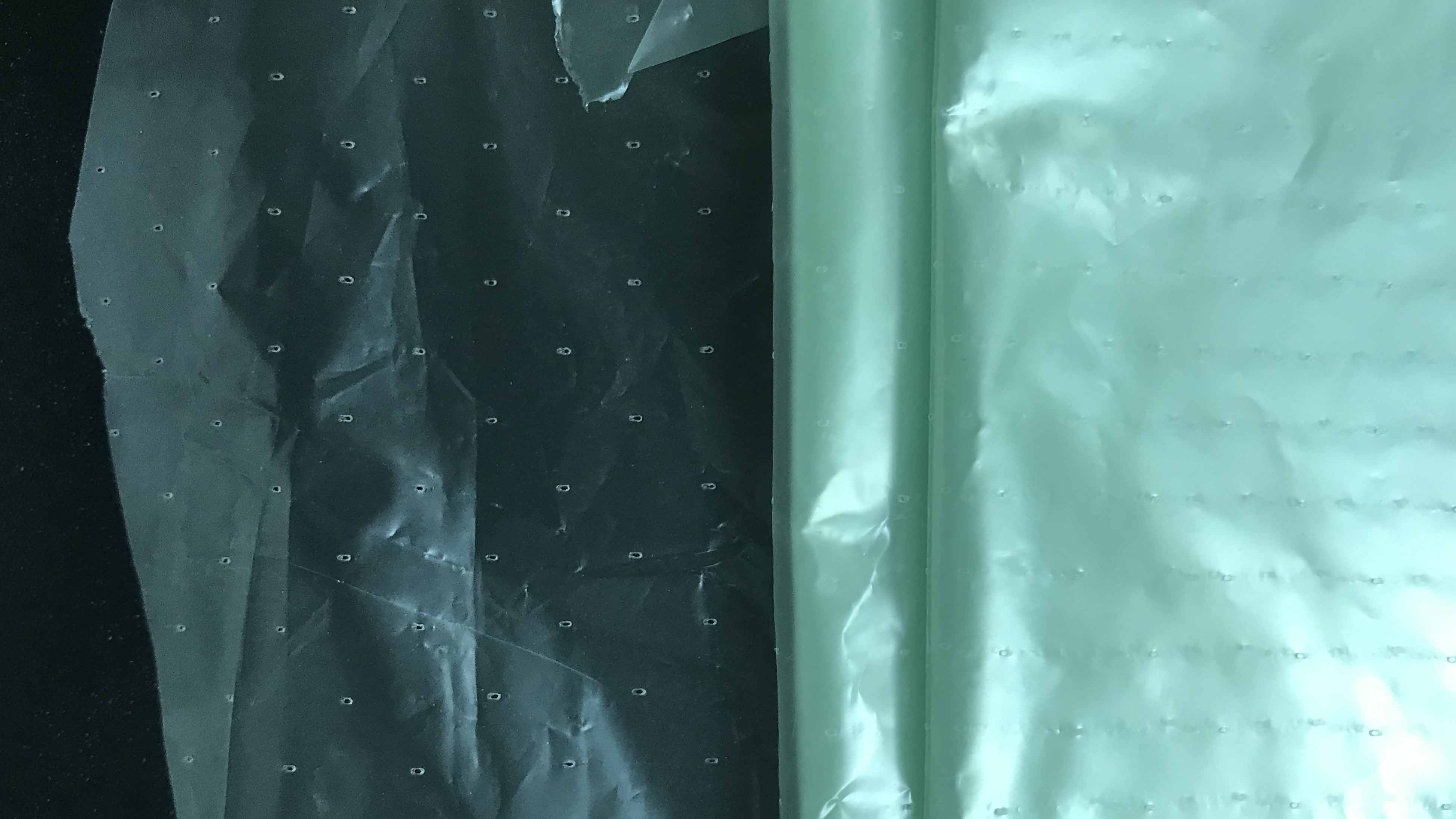
Bleed: is used to cover the composite. It is a plastic film with bleed holes when vaccum is applied, the excess resin will flow throgh this bleed holes
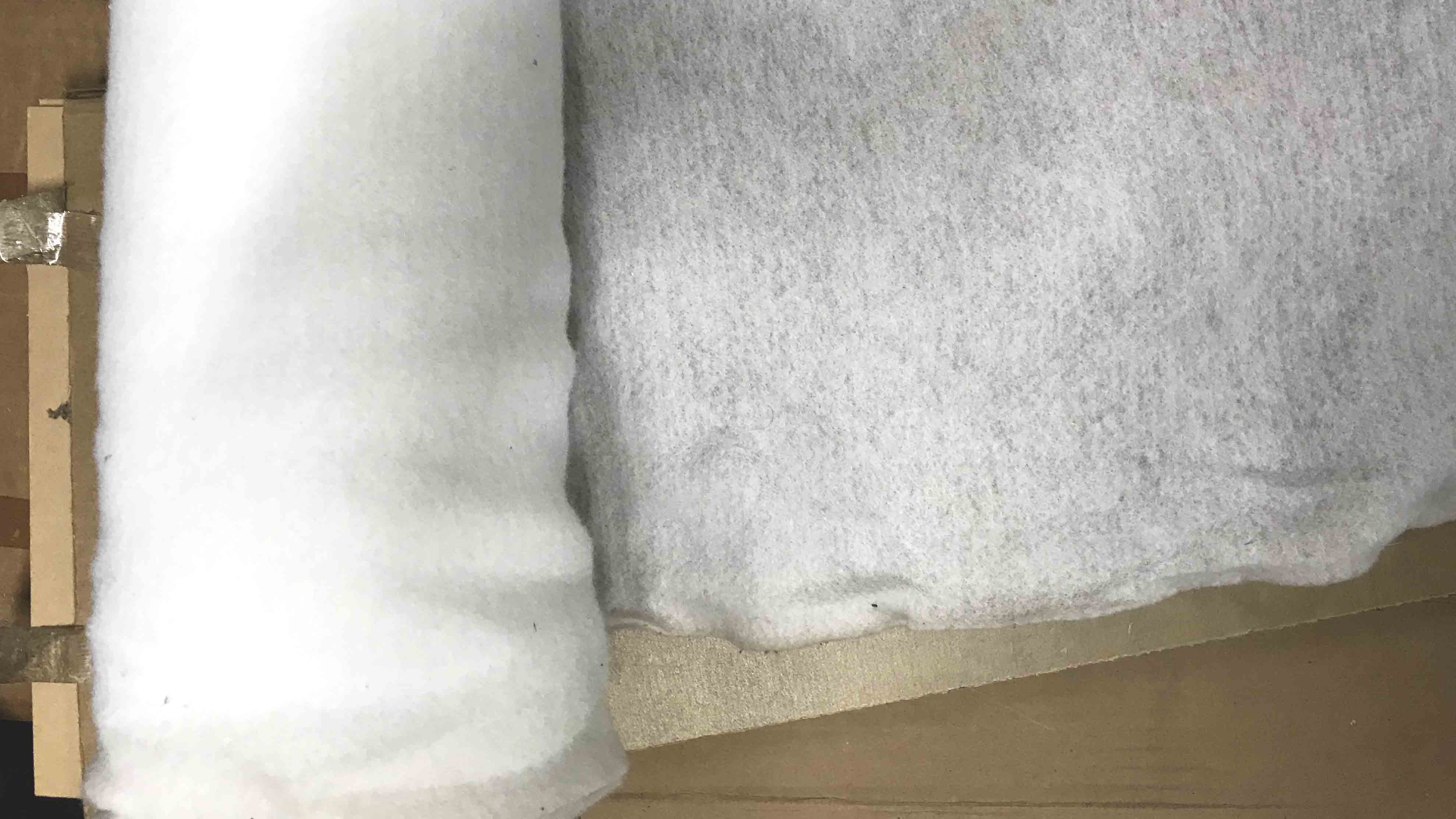
Breather is synthetic fibre used to release the mould
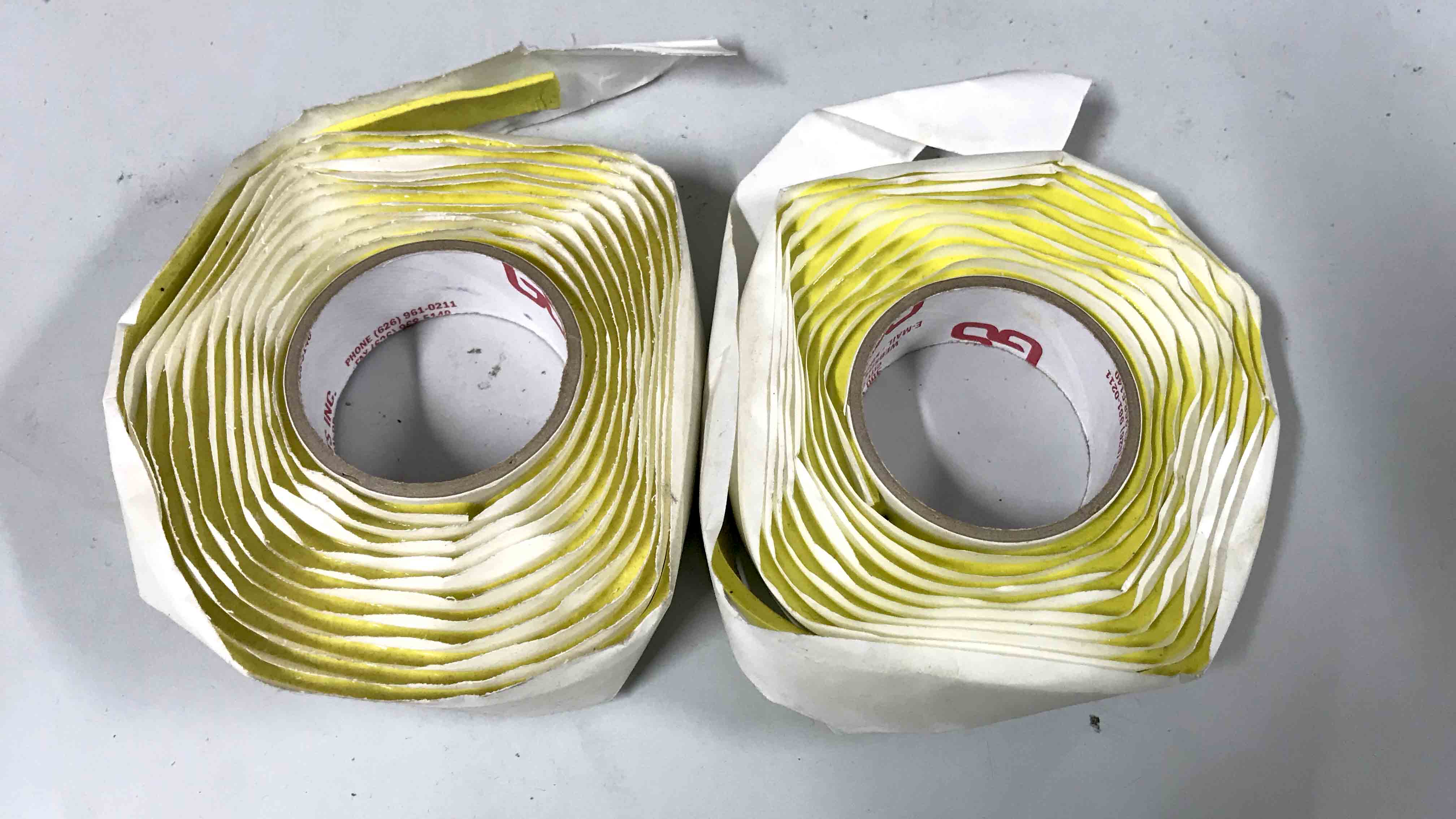
Tacky tape: is a butyl-based vacuum bag sealant giving high elasticity and tenacity. It has exceptional sealant properties, eliminating the risk of imperfect seals often found in the initial phases of vacuum bag application, so improving the vacuum efficiency and reducing labour. It is suitable for polyester, vinyl ester and epoxy laminating systems.
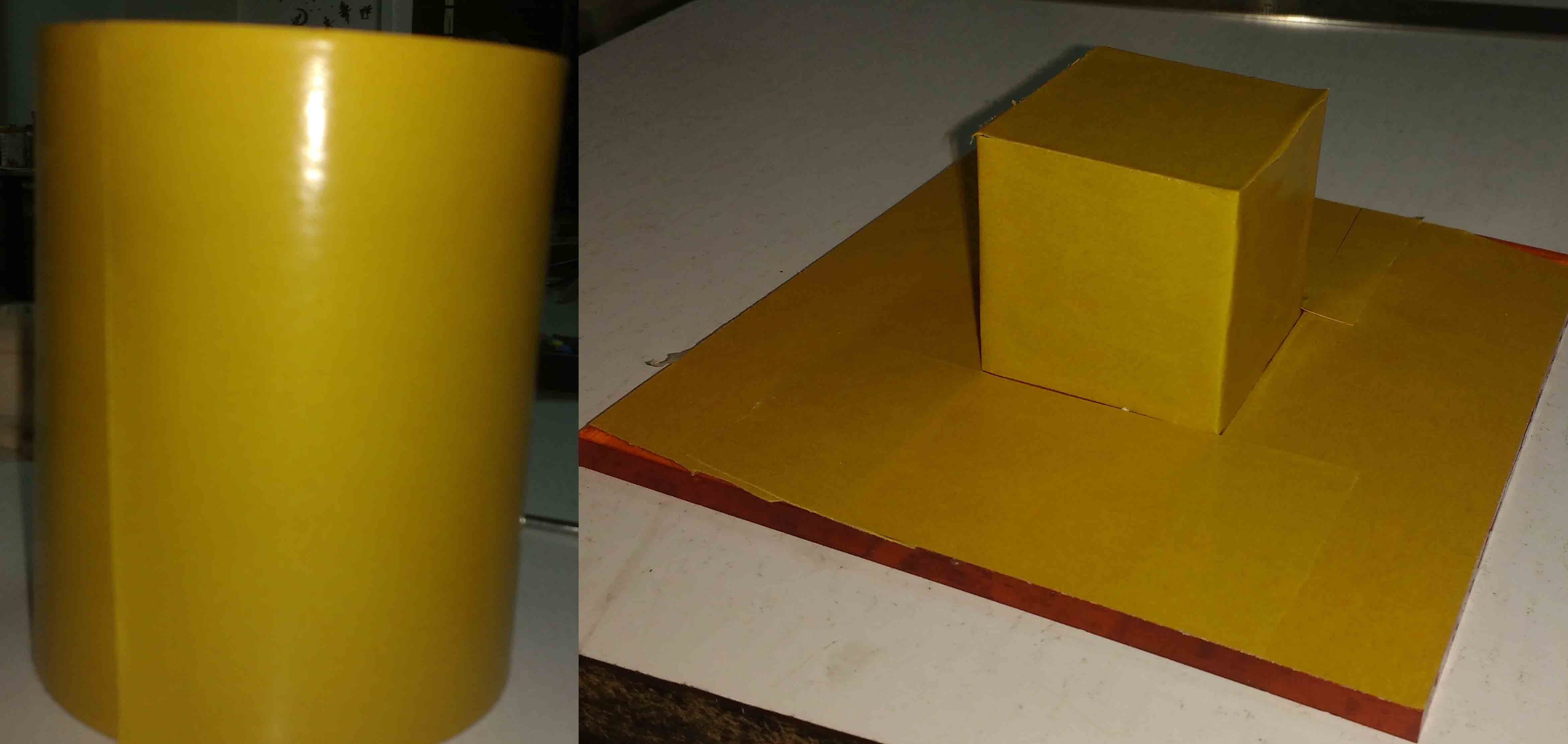
Cover the mold material with Release Film .I manually cutted the pieces with a pen knife. Otherwise the thermocol will absorb the resin and once it is dried, it will be difficult to remove the mold. . It is very difficult to remove the resin from clothes. so be careful when using resine
Laser cutting linen
in this time, The engnering graphic sections i learnd in my btech accadamic help me to make a design for cutting clothes. I convert each surfaces to a 2D plane for cut the clothes.
please refer my Computer-controlled cutting week to know how to use laser
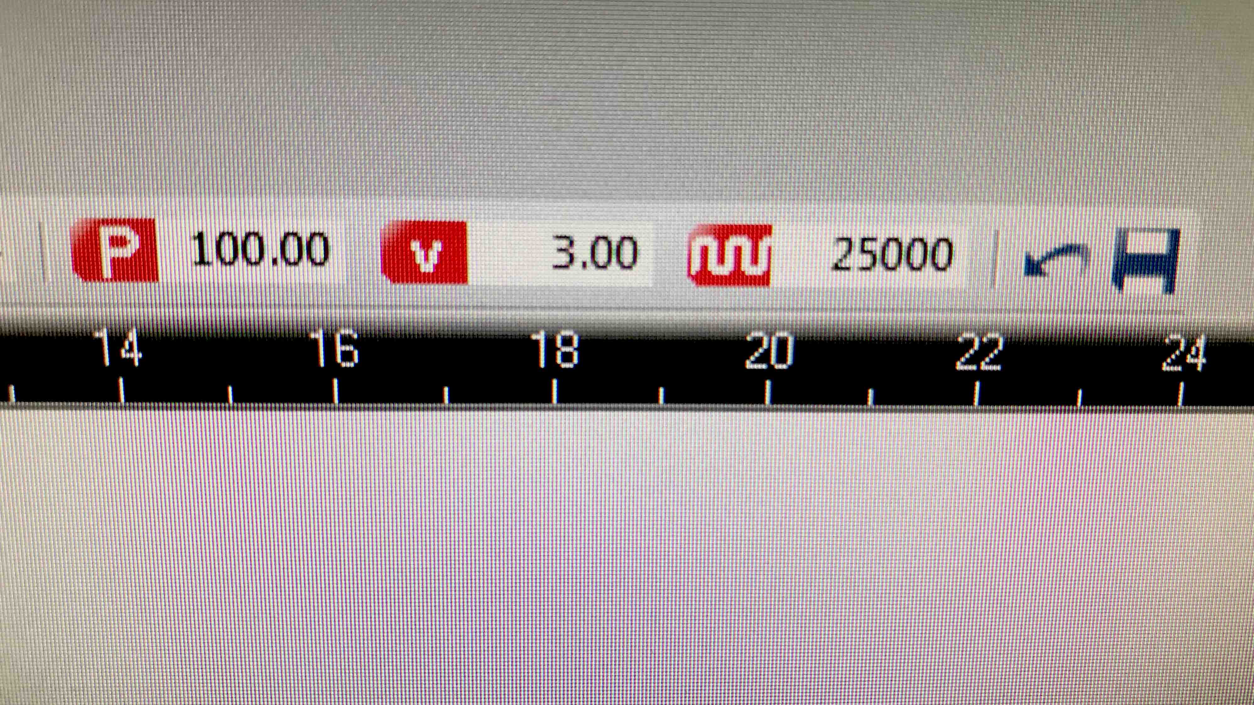
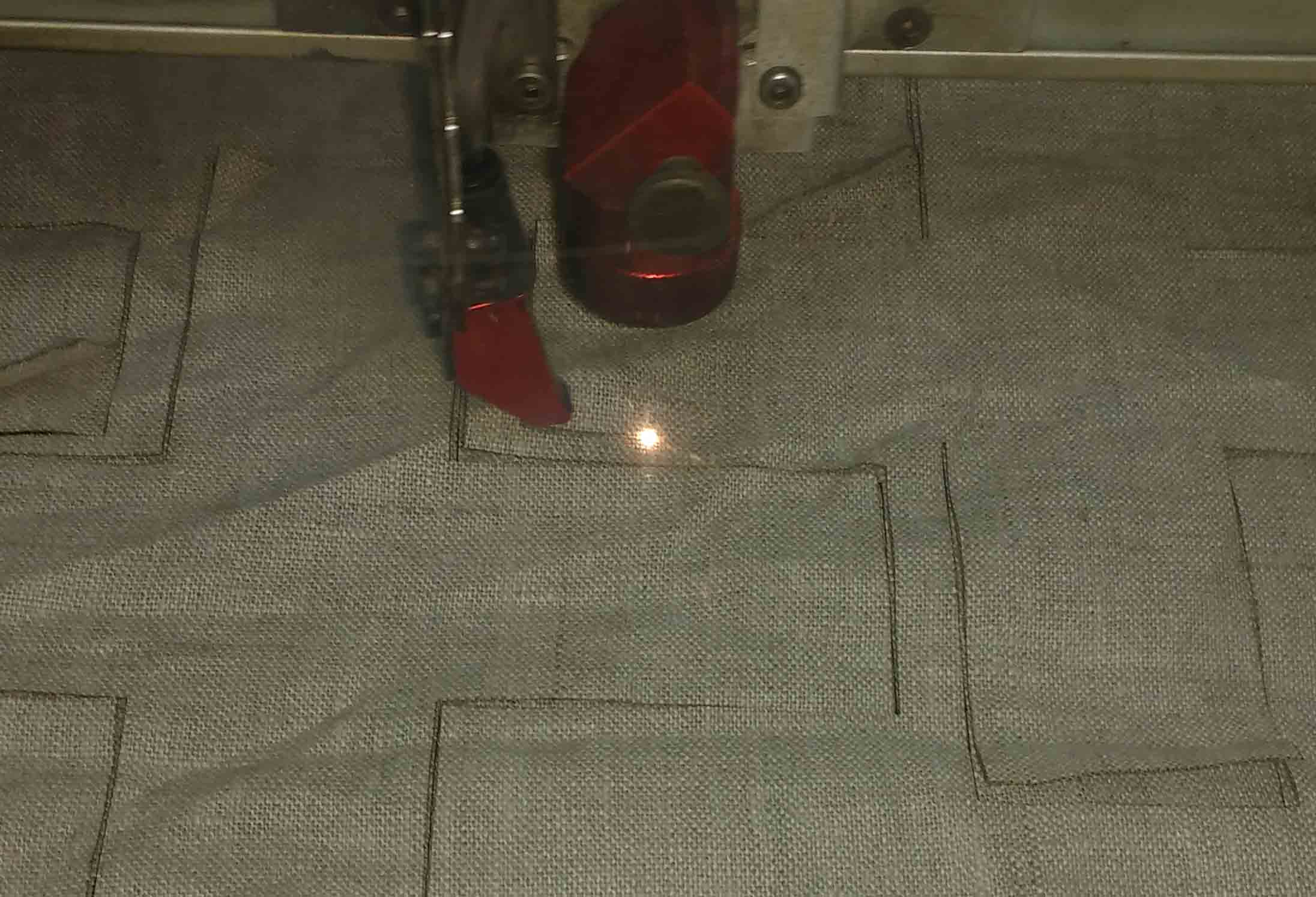
After focusing i cut the linen with the following settings
Then i cut the linan into peses
Casting the part
I used Easy Cast Transparent Epoxy Resin and it' having mixing ratio of 100A:50B and the curing time is about 24 hrs. This item i use in Molding and Casting week.
so please continue only after reading the instructions and safty precautions in that week. The mixing ratio and preprations are detailed in that week.
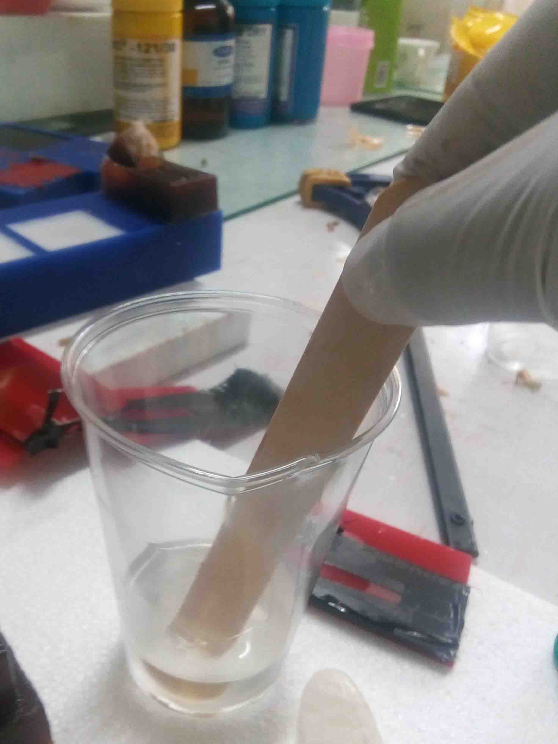
mix both parts with a stick, improper mixing may lead to problems in curing
Gently sock the fabric inthe resin and lay alternatively .1st lay the vertical pieces and then the horizontal pieces. Apply 2 or 3 similar layers above it .
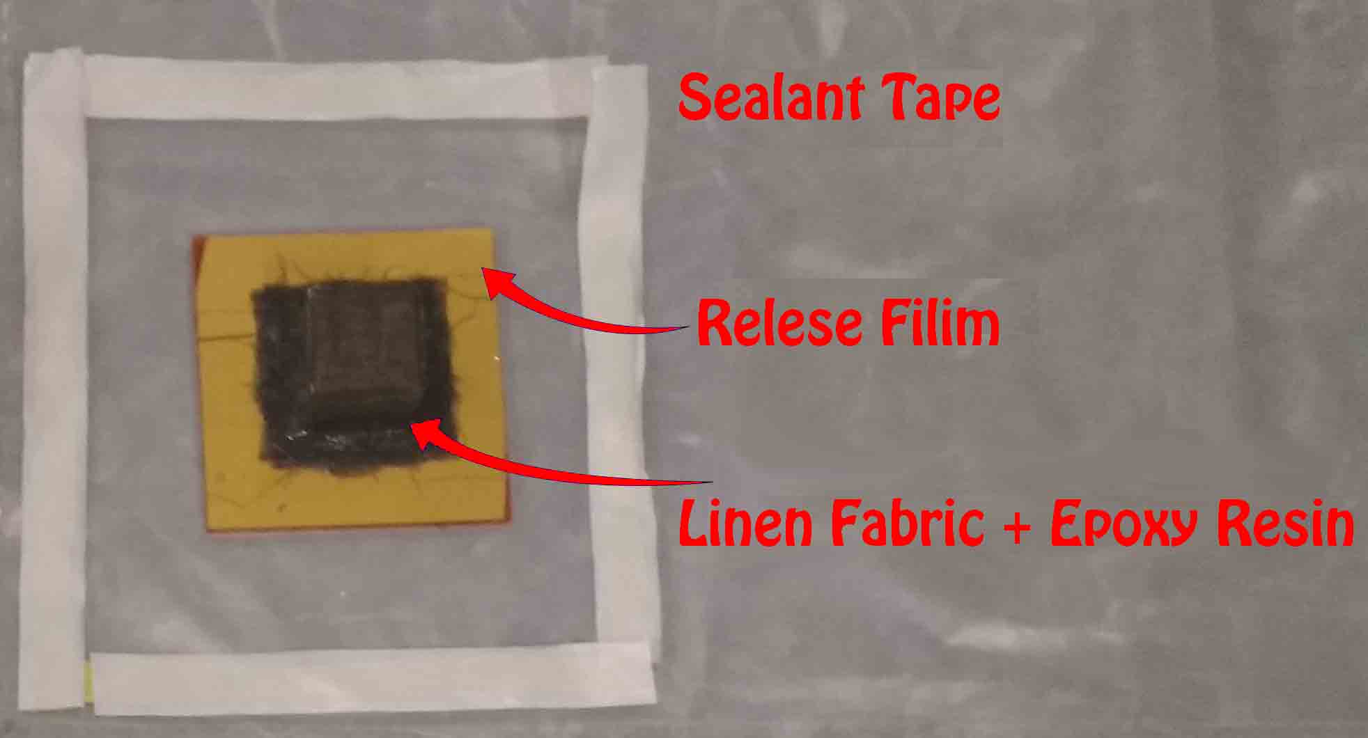
Place the mold and composite on the preset vacuum bag.The bag shoulg be prepared befor mixing the resing . It will ease the vacuuming process to suck excess resin from the composite.
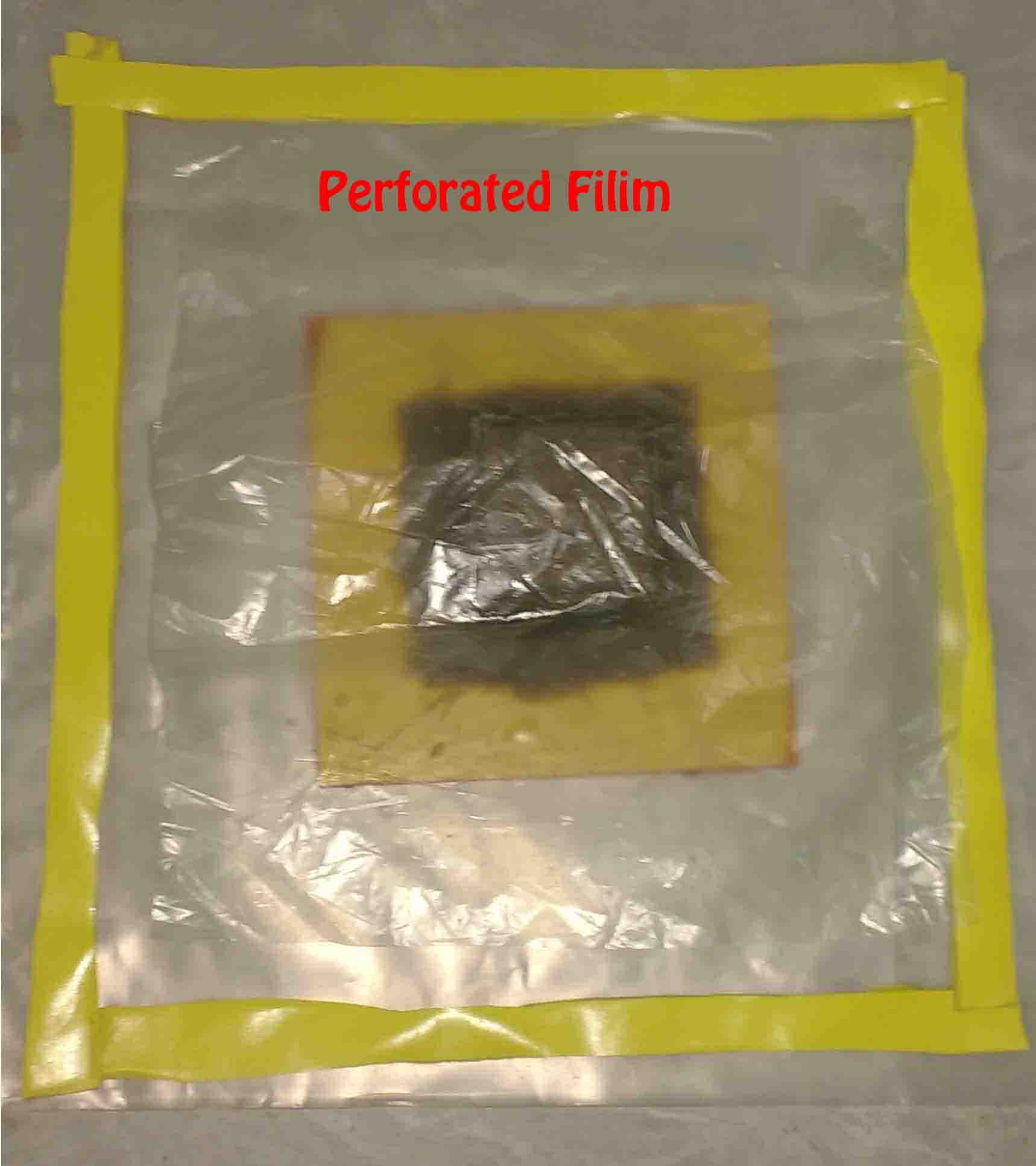
place the composit above the base of vacuum bag .Then place the perforated filim above it .
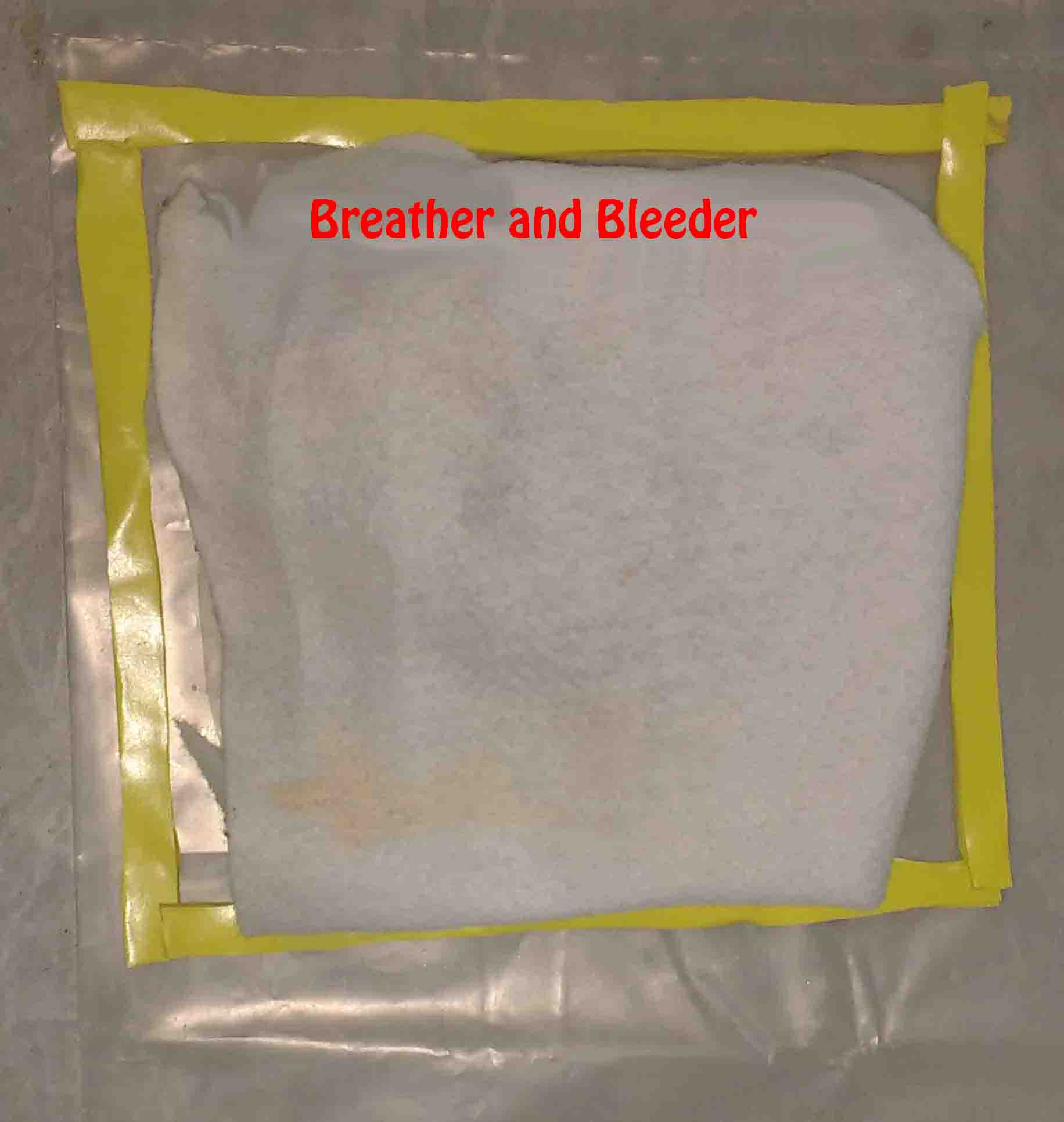
Place the Breather and Bleeder layer above it
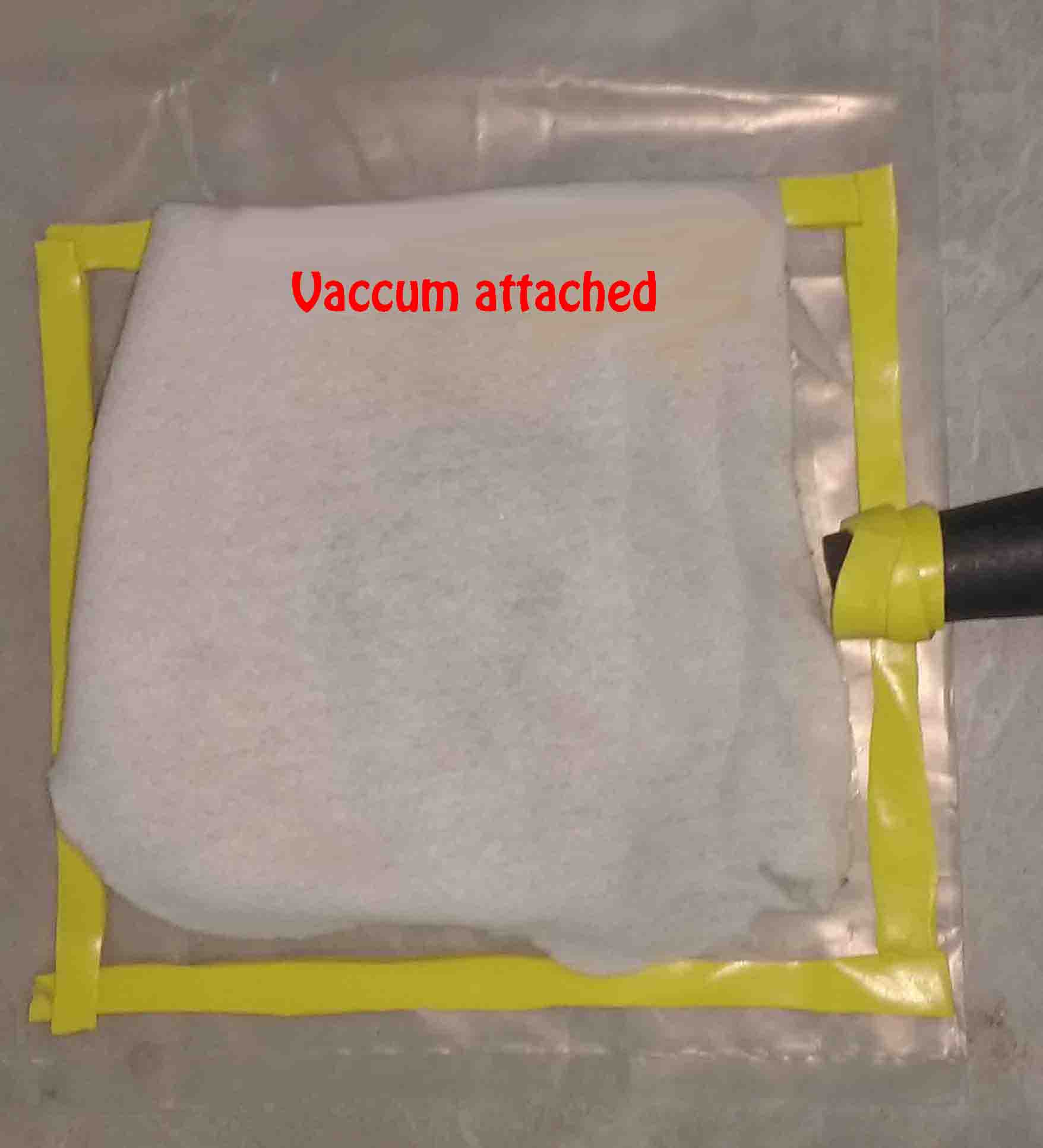
At last seal the bag by placing the top of vacuum bag.
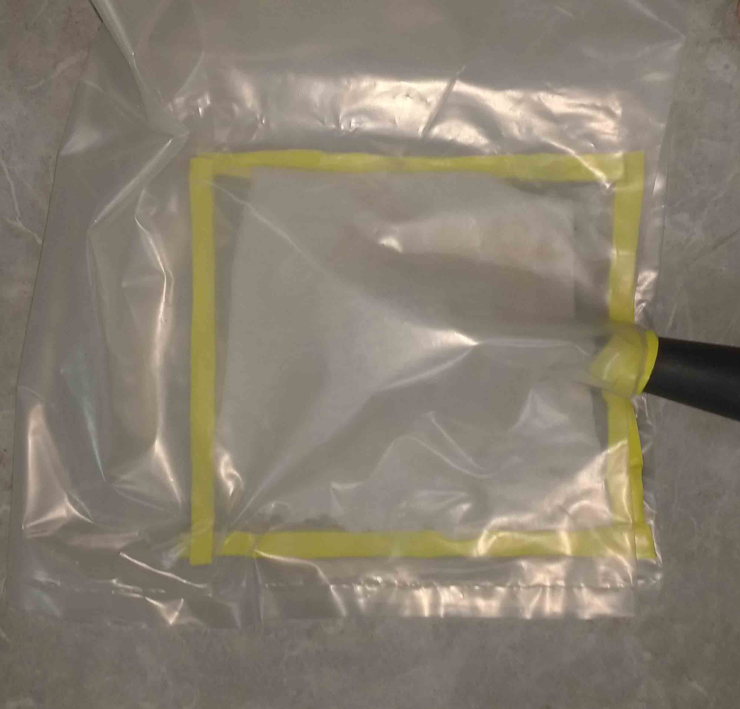
Connect the vacuum hose to the bag and start the vacuuming(I used vacuum cleaner for this).
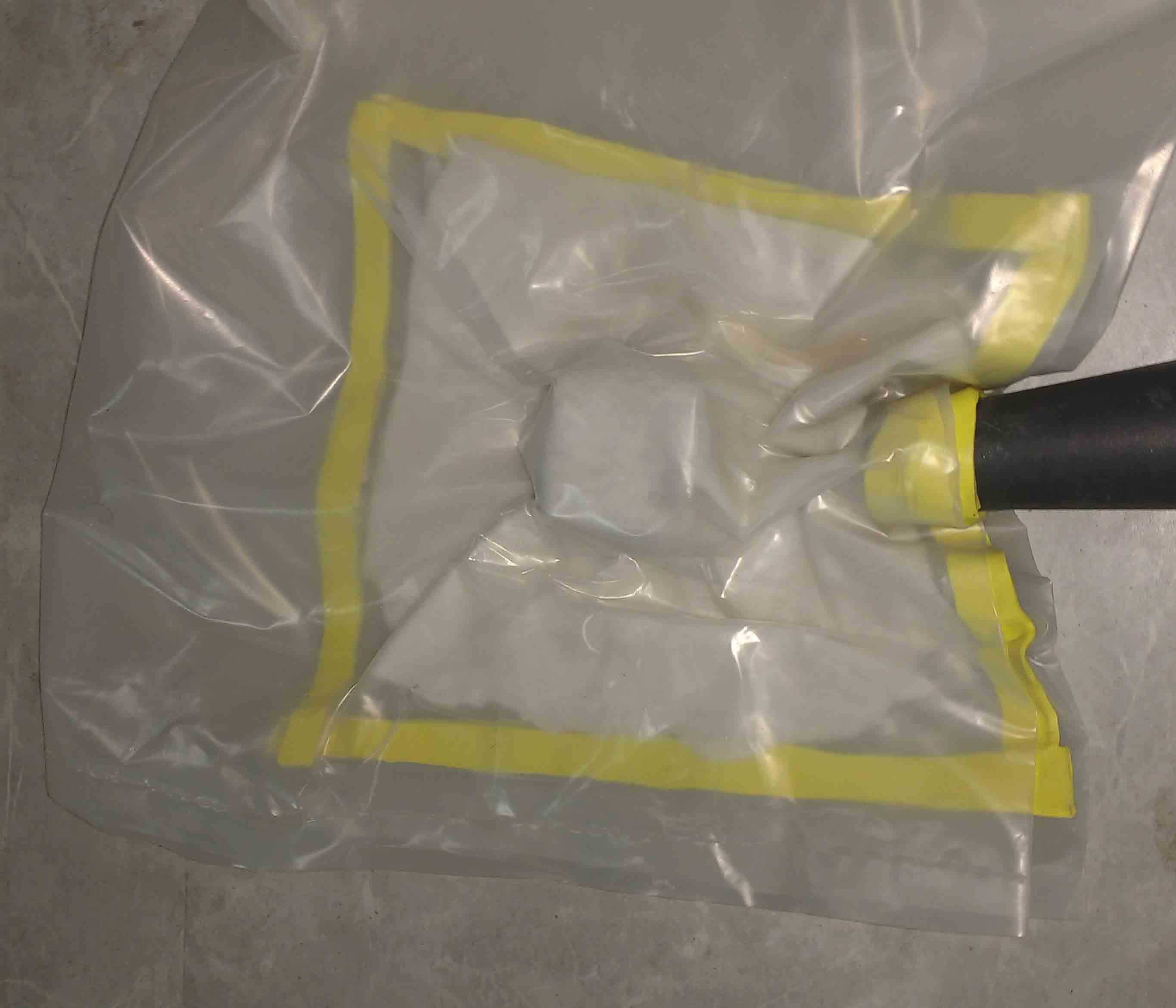
Then turn on the vaccum cleaner. it will suck air from the mould.
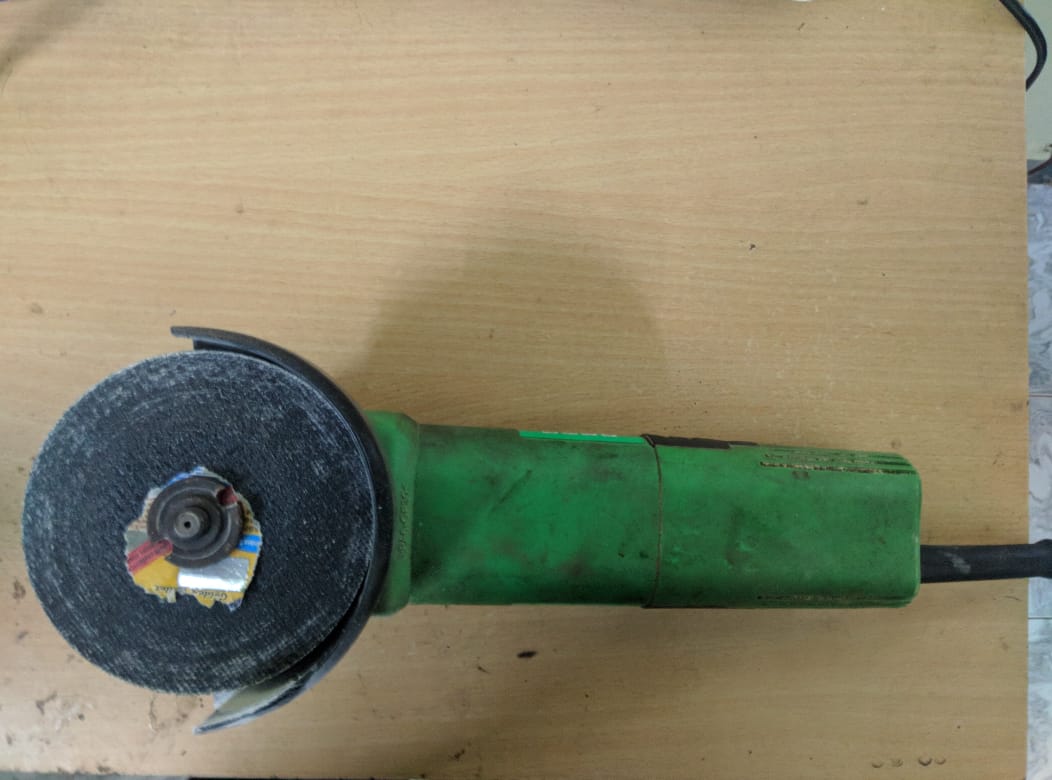
I let 24 hour for the composit to cure.Carefully remove the composit from the mould and trim the excess material. using an angle grainder
Finaly i got the following item, but unfotunatly this is failier for me because, the inner parts are not flat, so the motor cant cover using this. so this is totaly useless for me.
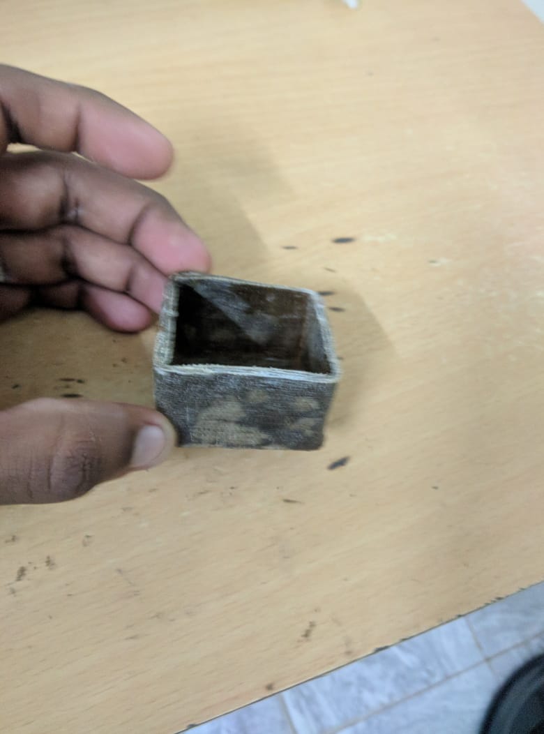
I find the problem, that when i try to press the composit layers, the thermocall block also pressed this lead to the non uniform walls.