Make Something Big!
Test Runout, Alignment, Speeds, Feeds, and Toolpaths for your machine
For this assignment I decided to make table . As I mentioned in Week4 Computer-controlled Cutting The design of week4 will help me in Week8. in week 4 i design a test part of the table , But here is the first step towards my final project .So intially i started work on sketch of the table where i discussed with my local insrutors Mr.Soahil Ahmed Somroand Mr. Noor Ahmed Pirwani.After discussing i started make sketch of the table in board and also tried on paper to clear sktech in my mind.
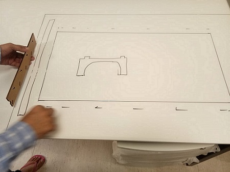
Sketch On Table
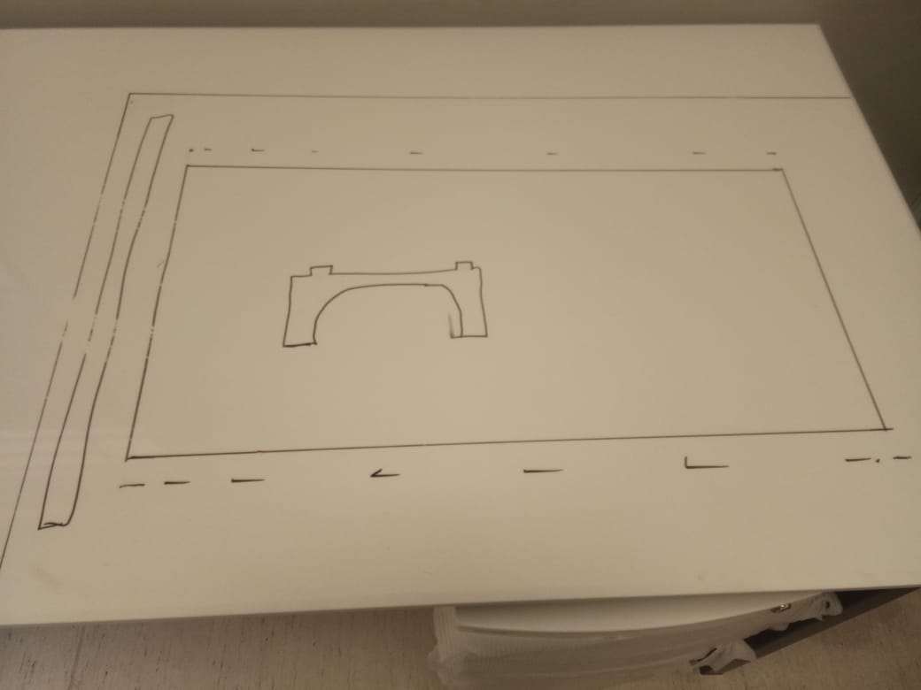
Anoher view
After doing this the next step i did is draw sketch on paper to clear my mind about design.Like how it looks like after designing etc.
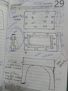
Sketch On paper
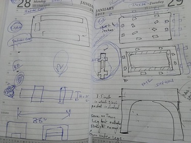
Sketch On paper
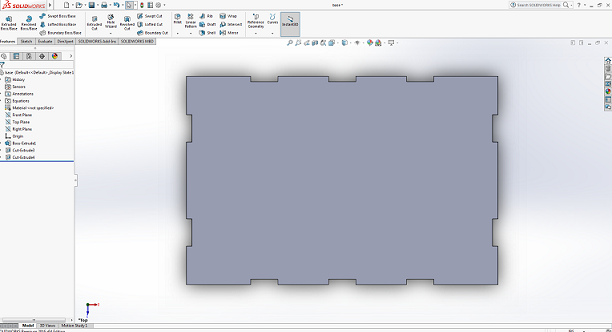
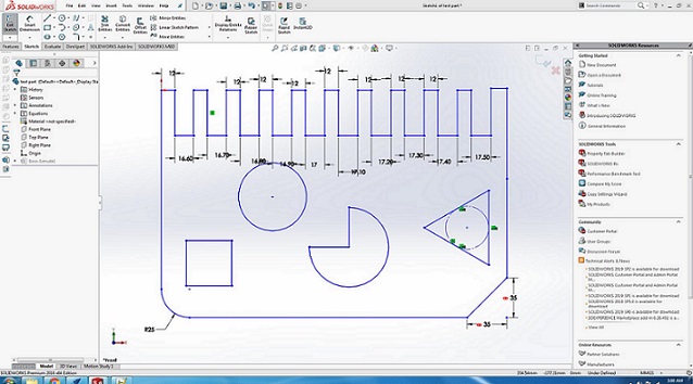
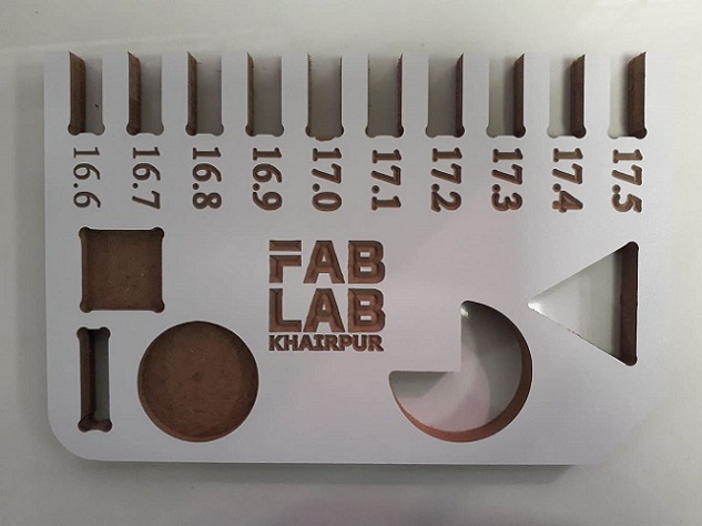
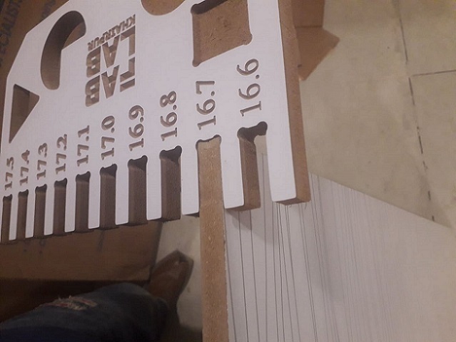
As i already mention that i have design test part of the table in week4 , So in this week I actually implementing that test part using CNC milling (Shop Bot). just i have to make that design accordingly , and setting things according to CNC Milling .
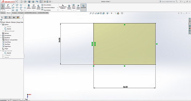
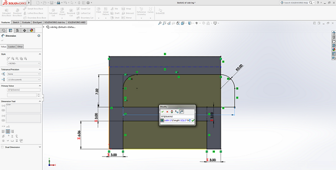
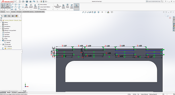
Defining The Dimensions
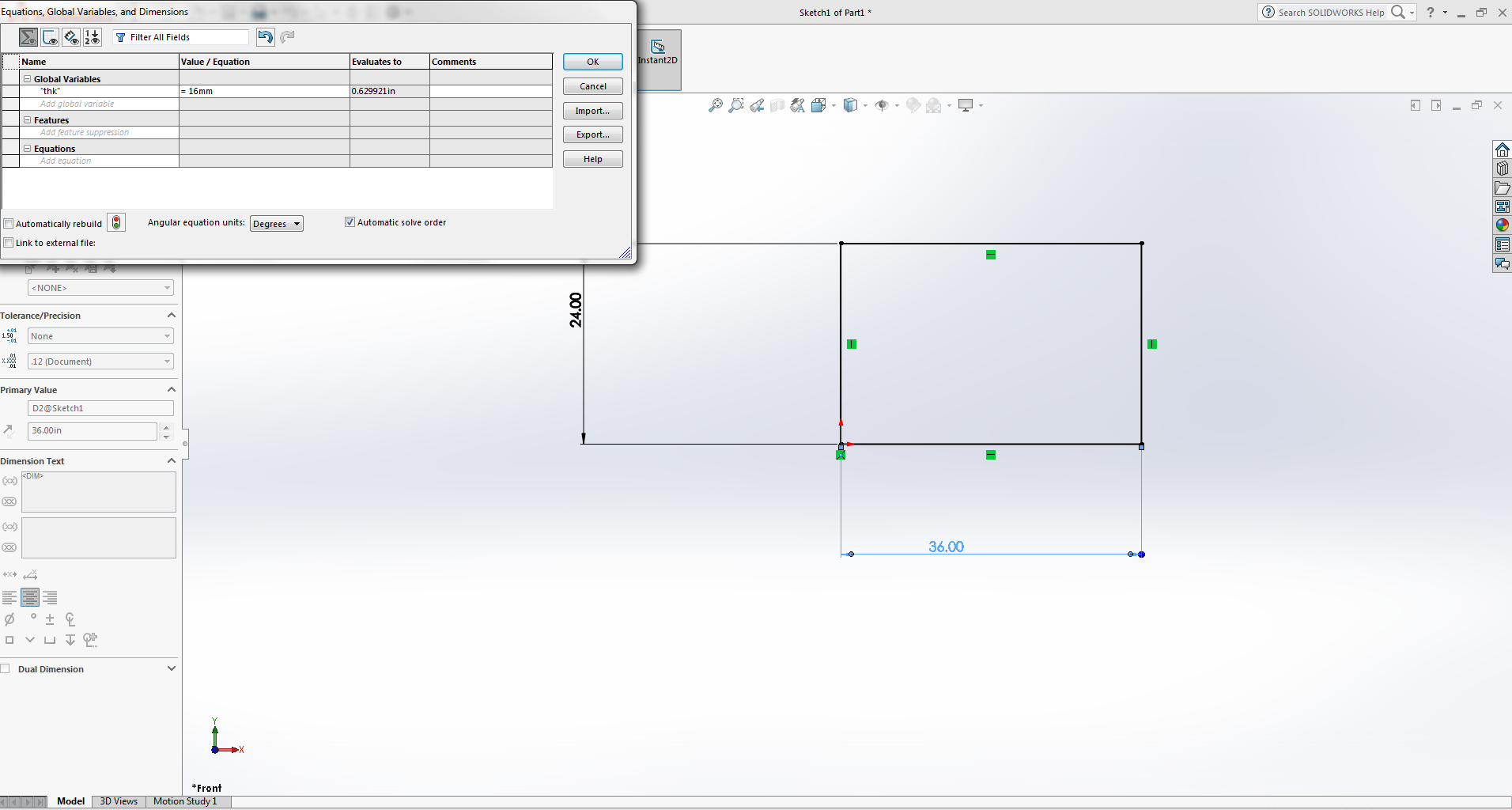
Definig Parametric Equation
Definig the thickness parameter as variable. I defined global variable name "thk" value 16mm according to the material thickness.
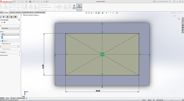
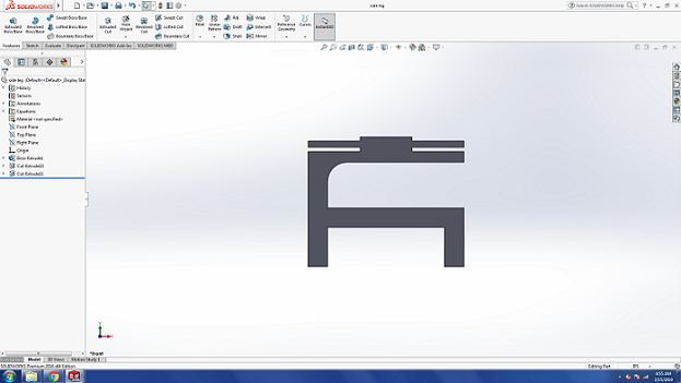
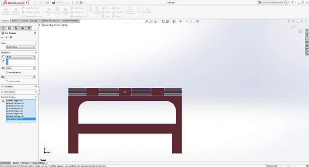
After Extrude Cut
Side leg
After Extrude Cut
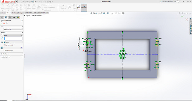
cuting outside from top
I did this by using the tool mirror entities.
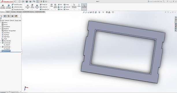
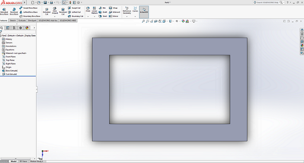
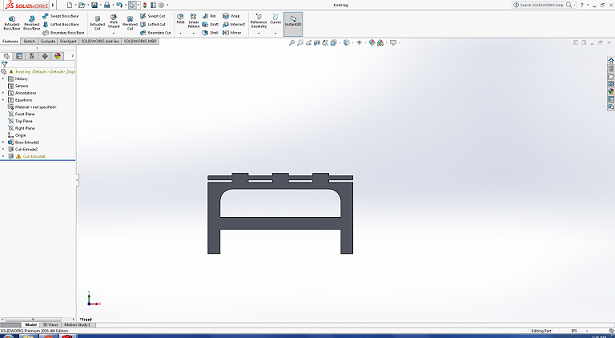
After Extrude Cut
Base
Now the next step is to make side legs from other side that is little grater than previuos side .
Base
Extrude Cut
After Extrude Cut
Now all the components are ready the next step is to assemble them . All Compoenets are put into assebly file where i mate all components.
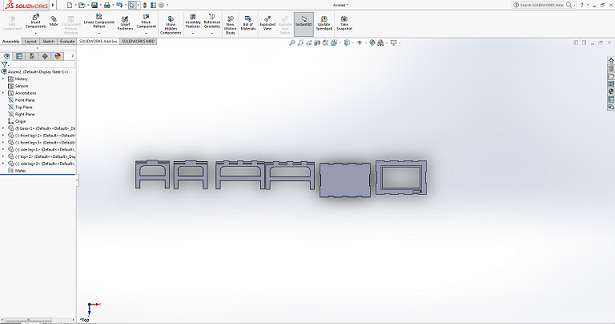
All Components are in Assembly
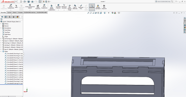
Final table
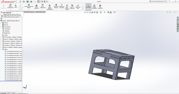
Another View
After succssfully doing assenbly the next step i did i make drwaing from assebly file , for dfx file
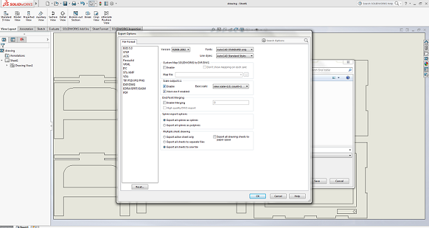
Making Drawing
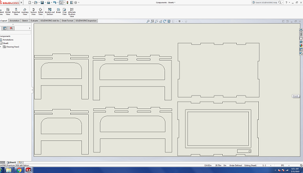
Making Drawing
The Next step afer dfx file is to generate G_code for shopbot machine for this i used Vcarve. Where intially i setting design according to the material size that we have and te toolpaths according to the design. After that i performed joining and dog bones repectively.
We are using VCarve Pro Software to generate the G-Code for ShopBot, below we described each step for this process:
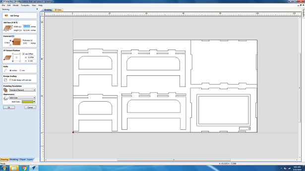
Fill the job setup menu by entering board dimensions (width, height and thickness), set the XY Datum Position by clicking on bottom left corner, set units (our dxf files are in millimeter so we select "mm" in this column) and in last for appearence we select MDF because we are using MDF, then click "OK" for file operations.
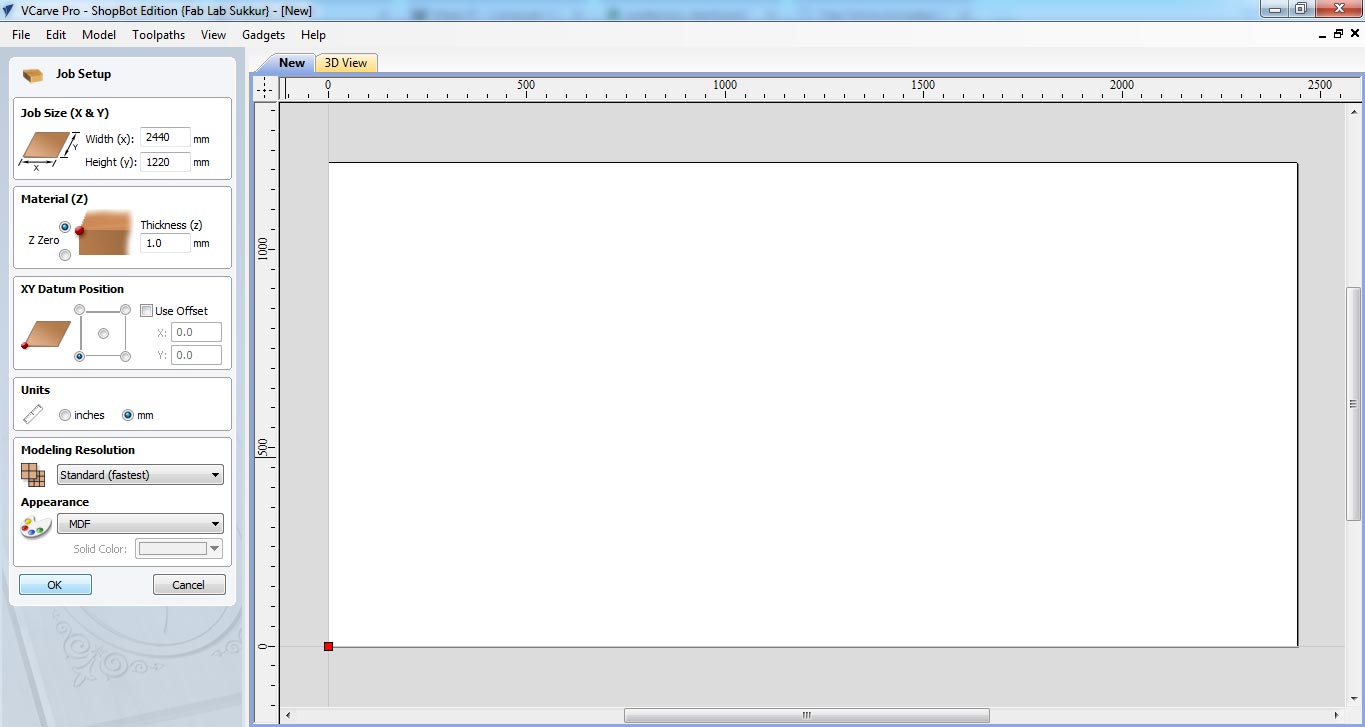
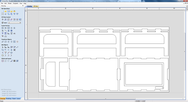
To generate a toolpath a vector is required, so we draw rectangle on whole board.
after making vector now we are setting up the toolpath. Click on "Pocket toolpath" option in toolpath tab, then set the cut depth to "1mm" this shaves the whole board over 1mm, then select the "tool", in our case we select 1/4" Spoil-board cutter (the picture of the tool is mentioned above). Now select the vector, name the toolpath and click on "Calculate"
Adjusting the components
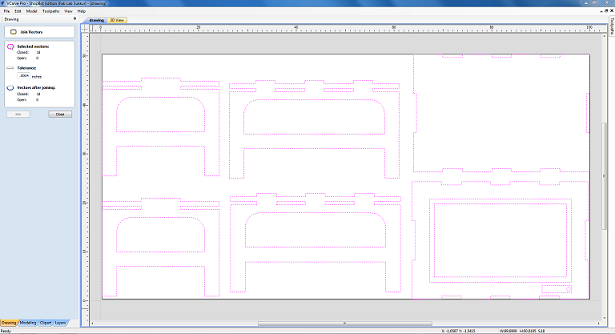
Joining
DOG-BONE:Dog bone corners are a jargon-y way to describe the shape of a corner that is extended outside the cut area to create a perfect 90º corner that looks like the cartoon shape of a canine chew toy.We used dog-bones for this problem in the design, For this command we have to just click on the filletcommand from the edit objects menu and from there we can select dog-bone and edit the object's corner. For further understanding you can click HERE .
DOG-BONE
Tool Information
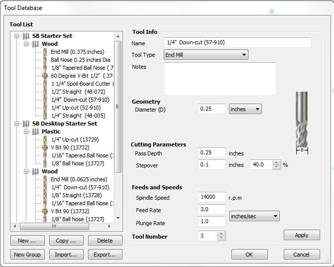
Tool Info
In the above image you can see the values of rpm,feedrate, stepover ,tool-diameter etc. basically these are the by default values and in our lab we mostly operate the machine on these values , so for I did follow these values and operate the machine and the result was completely accurate. So for we did cut the test part on these by default vales and also cut the final part on these values.
Shopbot software
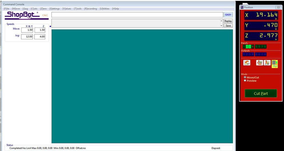
Shopbot software
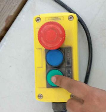
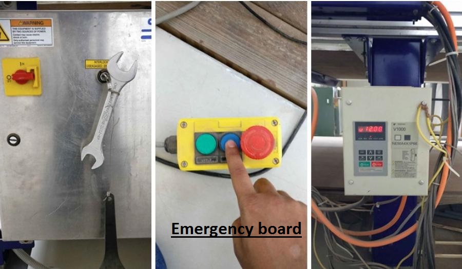
Emergency board
After Generating G-code the Next step is to finaly start cutting with Shopbo. Before doing that we need to make sure that the tools that we used according to the design and toolpaths that we generated or not if not so we need to change it. I used two tools one for writing fab lab khairpur name in legs of the table and second for other design
While Changing Tool
After changing tool i ready the job for CNC machine. Initially i cut the name that i want in table side and i changed tool accordignly.
Cuting Name
Cuting Name
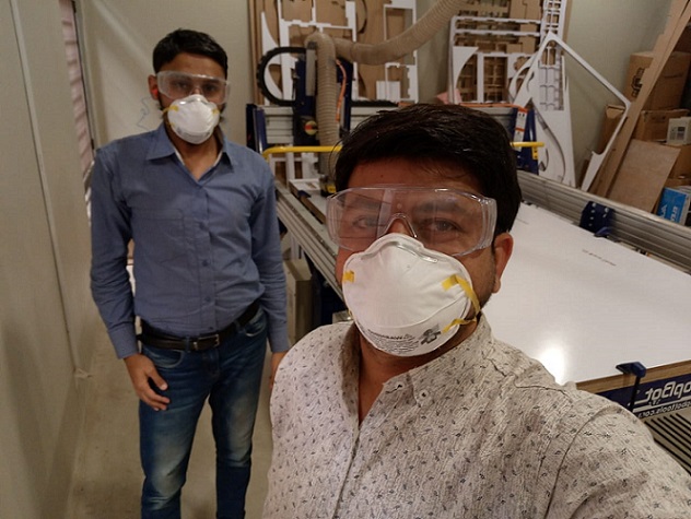
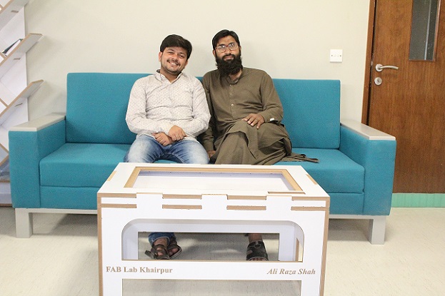
With Local Instructor
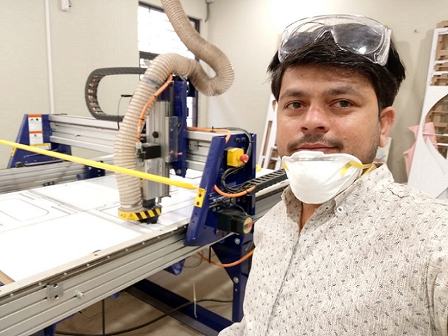
Selfie :-)
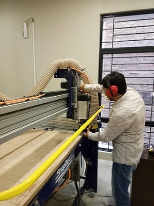
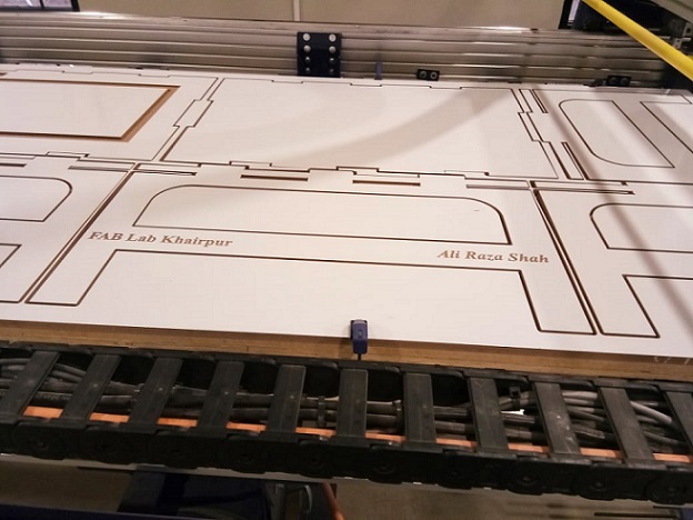
After Cutting the name the next step is to cut other compoenets for that i need only one and same tool for cut so i changed tool and given job to machine
Cutting Others part
Cutting pocket
It akes almost three hours to complete this job.Finaly here is the almost complete cut of the design
Almost completed
All parts
After cutting te next step is main and most critical part of the this week assingmnet is assmeblig the compoents .I taken almost three hours to assmeble the all components because before doing this we must be careful about the critical parts and sides of the design.
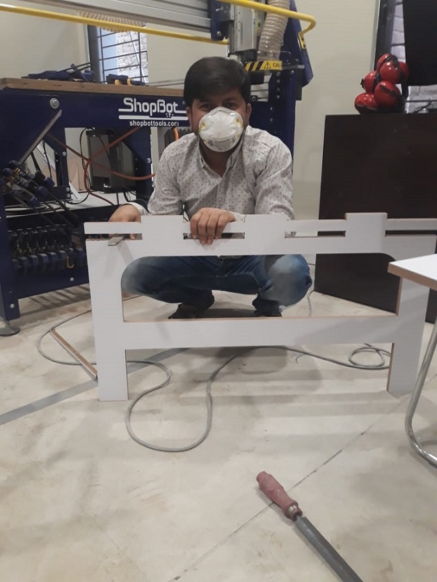
While assembling the compoenets
And here is the final design that is ready.
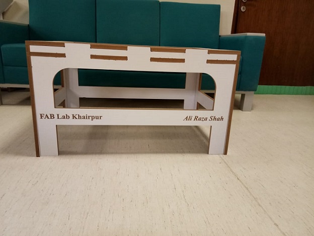
My Table
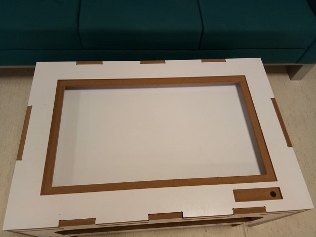
Top
Hero shot:-)
What is CNC Machining ? CNC Machining is a process used in the manufacturing sector that involves the use of computers to control machine tools. Tools that can be controlled in this manner include lathes, mills, routers and grinders. Initially we learnt how to run the cnc machine which is described below. For this we made a design in solid works and cut it in CNC.
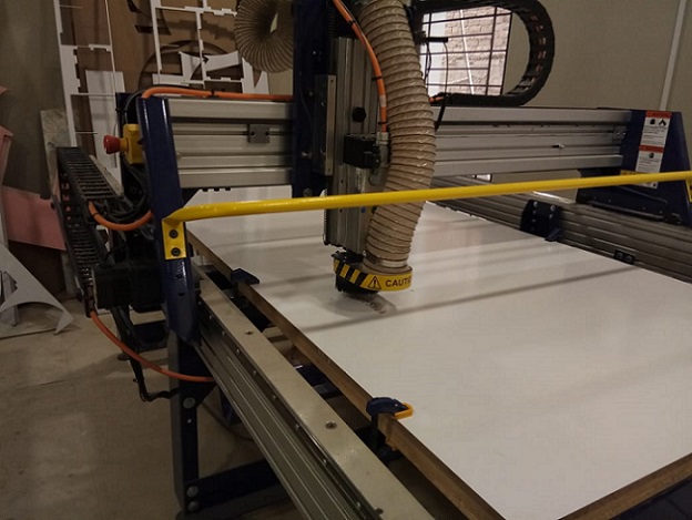
First and foremost we read this document where feeds, speeds and other stuff is explained very well after that we started with milling process so before starting with the milling process, the first thing that needs to be done is to install the desired milling bit, material and vacume chamber. The desired material can be placed and fixed tightly on the shopbot bedsheet. Placing the clamps is very crucial because if you placed them at wrong position then cnc machine might hit the clamps and ruins everything. Vacume chamber is also necessary which can be seen below in figure. This vacume is used to take off all the swarf outside of shopbot bedsheet and save in vacume chanmber. Furthermore it is very necessary that bit should be installed in the collet and this is done with the help of these special spanners. After doing this all we connect the system with the shopbot software installed using the 2 USB cables which are provided. On opening the software the axial location of the bit and a command like a screen appears.
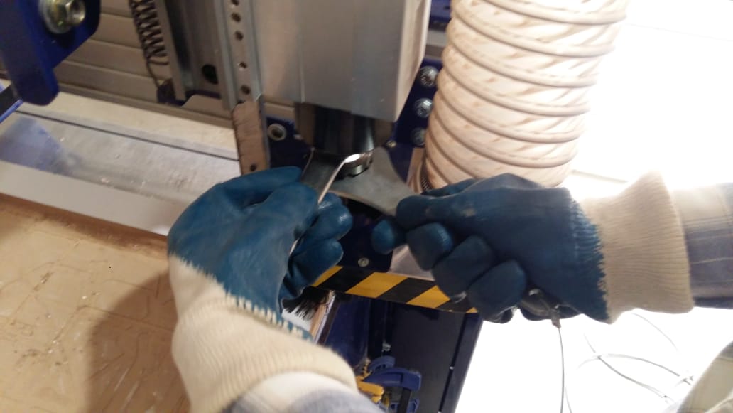
Installing bit
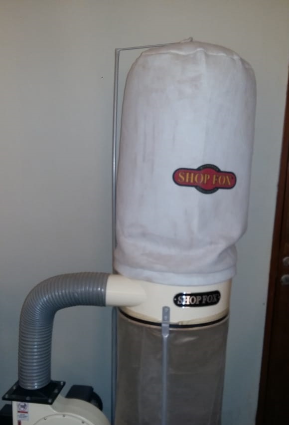
Shop Fox Vacume Chamber
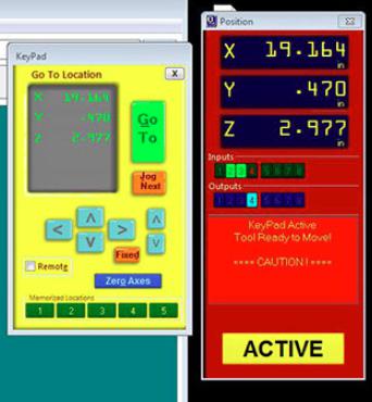
Now we need to move the drill bit to a point that we consider origin. To do this open the keypad option by clicking the yellow icon in the position menu. By using the arrow key or the on-screen arrows move the bit to the desired origin point. Setting Z could be slightly tricky. The bit should touch the bed exactly at a point that it scraps the top laye
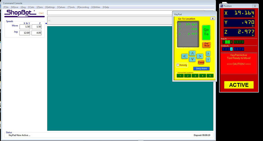
Setting Originr
The bit can be moved slowly by clicking on the fixed button. Once the origin is set, click on zero axes and set x,y, and z as zero
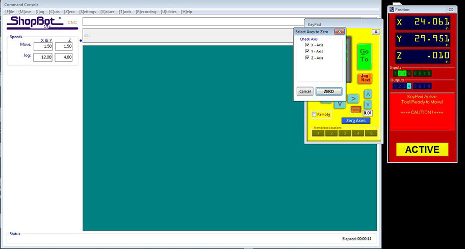
Setting x,y and z zero
Now its time to import the G-code into the software and this can be done by clicking the cut parts and choosing the GCODE file. Hit start. The code gets loaded up and a message appears to hit the start button in the control box.
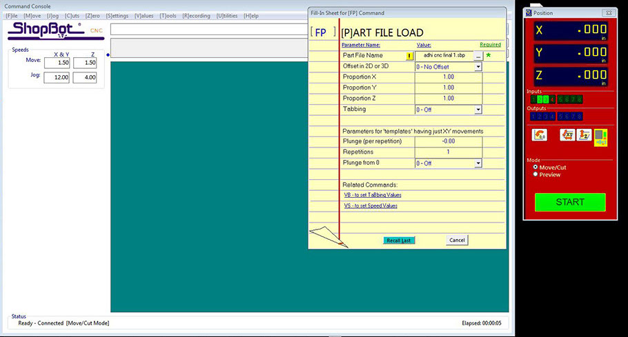
Importing G Code
Solidworks Design
After Cutting
After Cutting
It's All about this week , very creative and informative week so for and hope And many more to come!
You may Download all files from here
.png)