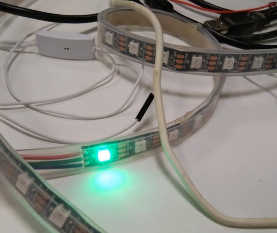
In this week group assignment we have to measure power consumptions of an output device.I Have used Led Strip as output device So I measured power consumptions over a individul Led in strip.
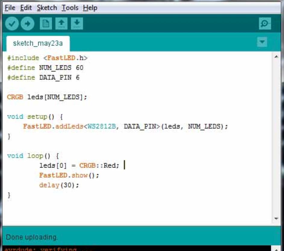
As one of our project is on RGB LEDs so we decide to find the power consumption of RGBs on different color pattern We write some codes which blink 1 RGB with specific color and measure current
on that project
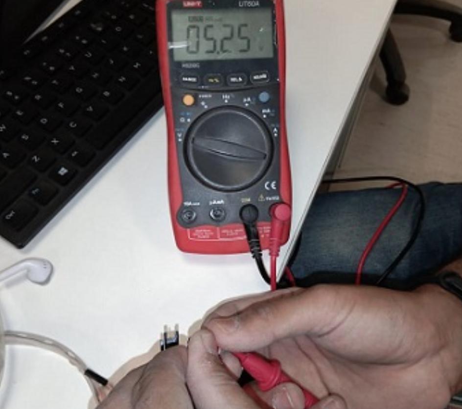
Current accros led
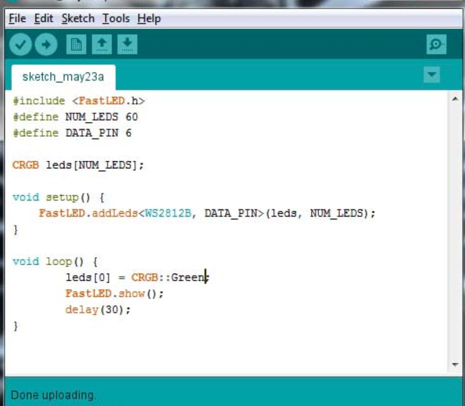
The current is measured 47mA which is multiplied with 5 Volts is equal to 235mW. Pogram For Green LED Green LED Current Across Green LED
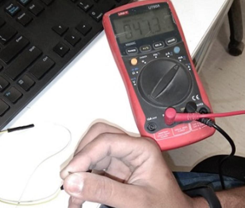
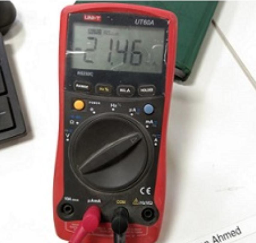
The current is measured 21.46mA which is multiplied with 5 Volts is equal to107.3mW. Same procss is used for other colors too.
Individual assignment
This is the 11th week of FAB LAB 2019 and its the week of output devices, on the 3rd april 2019 prof. Neil gave us detailed lecture on output devices and tols us about different output devices like RGB Led, LED array,
Displays, Speakers, different Motors, Hydraulis and many more. This is not the first time I am working on output devices but I ahve worked on different output devices, For the Individual assignment of the week I choose
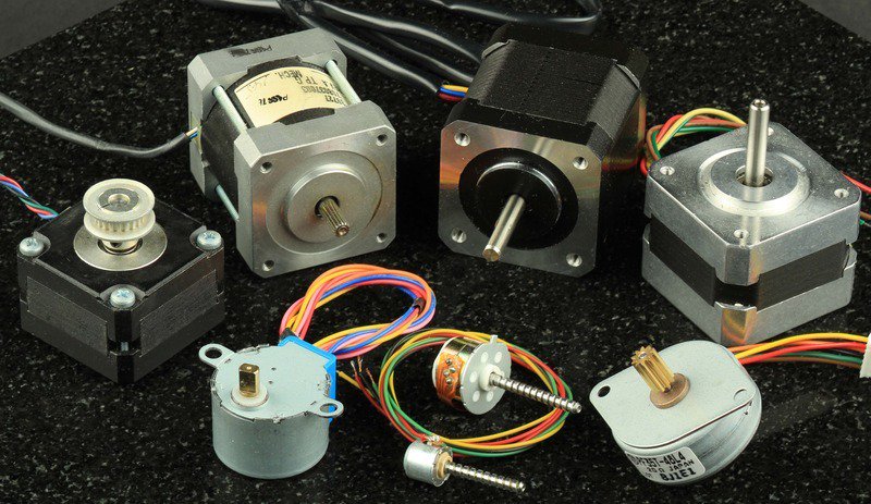
the Stepper motor. Previously I have worked with dc motors, servo motors adn BLDC but its first time I am working on the stepper motor.
Different stepper motors
Basically Stepper motors are DC motors that move in discrete steps. They have multiple coils that are organized in groups called "phases". By energizing each phase in sequence, the motor will rotate, one step at a time.
With a computer controlled stepping we can achieve very precise positioning or speed control.
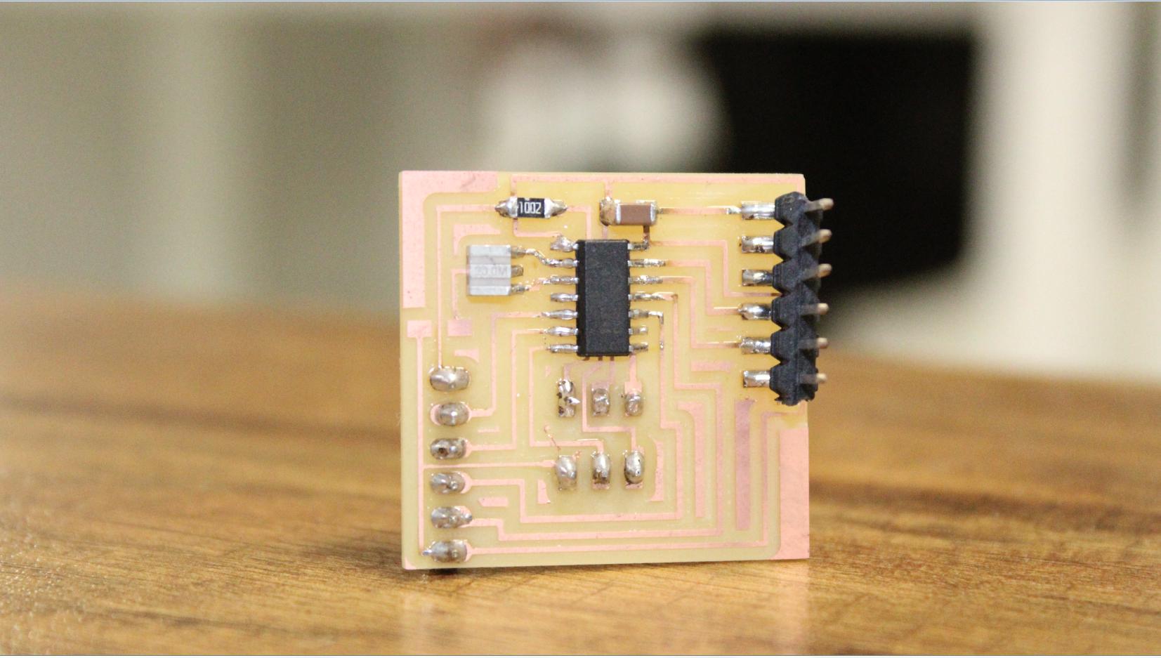
For the stepper motor first I need a microcontroller board and the driver. Last week(Week10) I made a generic board of the Attiny44 and now I can use that board and control the Stepper Motor, further
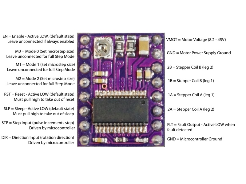
I have a stepper motor driver drv8825.
Attiny44 Board
The DRV8825 provides an integrated motor driver solution for printers, scanners, and other automated equipment applications. The device has two H-bridge drivers, and can drive a bipolar stepper motor or two DC motors.
The DRV8825 can supply up to 2.5-A peak or 1.75-A RMS output current (with proper heatsinking at 24 V and 25 degree C).A simple step/direction interface allows easy interfacing to controller circuits. Pins
allow configuration of the motor in full-step up to 1/32-step modes.
The Stepper motor Driver
drv8825
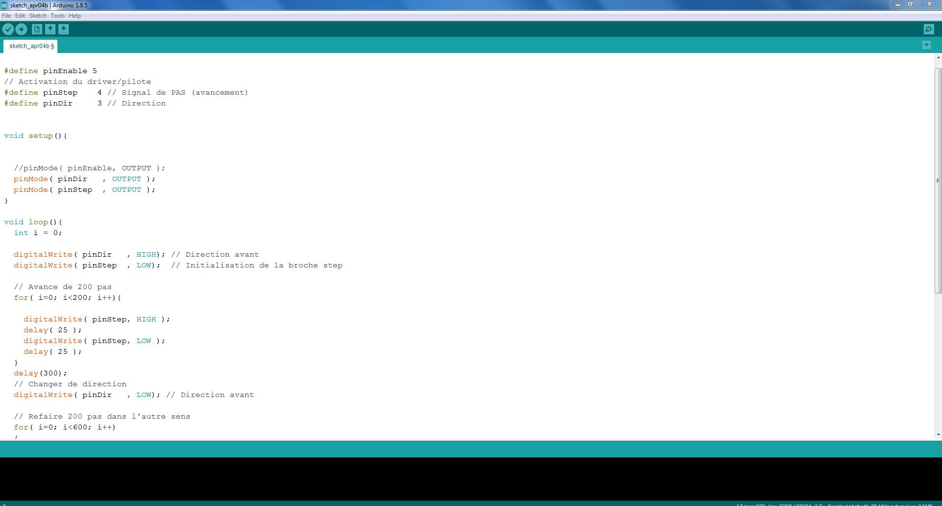
Last week I used this Attiny44 bpoard with the Ultrasonic sensor, now I have to just write the code and upload it. For this purpose I am using the Arduino IDE.
There are two ways to control the stepper one is we can use the stepper motors's library so we can use differnt commads and can control the speed and direction
of the motor, anr the other way is the simple way, we can simple use the pinMode and digitalWrite command in Arduino and can make the direction and step HIGH and LOW. I am using the 2nd simple way.
Writing the code in Arduino IDE.
Arduino IDE
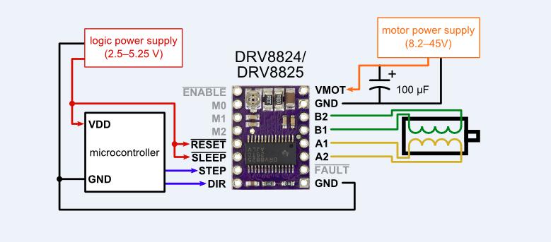
Connections
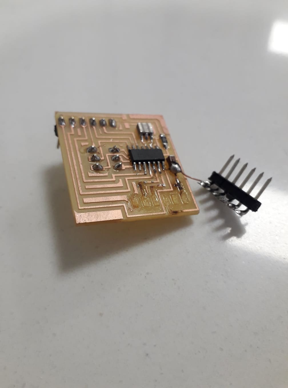
Actually during the wirring process I made a mistake and the board was badly damaged by Me.
Attiny44 board
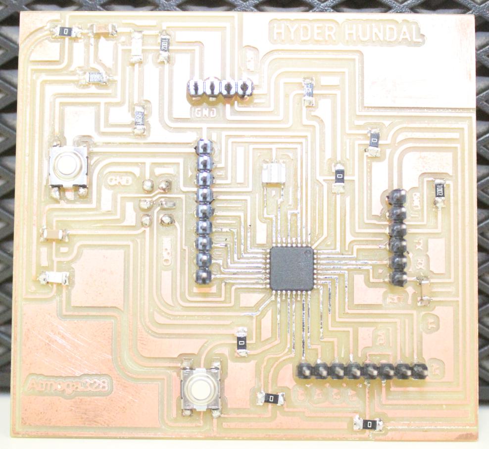
So now I am using my board of final project(atmega328p board), I will upload the code in this board and will run the stepper motor. Basically I need two digital pins, one digital pin for the direction and one PWM pin
for the step of motor.
For the further information about my attiny44 board and files you can click HERE.
For the further information about my Atmega328p board and files you can click HERE.
Atmega328p Board
Finaly I did upload the code and run the stepper motor.I am using the nema 17 stepper motor.