Electronics Design
This week's assignment is about the design process of a microcontroller board. I decided to not only make the board, but make it do something. I will 3d print a cube that has leds on all of it's six sides and only the one on the top will light up. To do that I will use an accelerometer for which I will have a dedicated connector on the board I will design.
So first of all, Eagle is really easy to use to make a board you basically only need 3 functions:
First is the add part function

It allows you to add components from a huge list preinstalled parts and can be augmented with downloadable libraries.
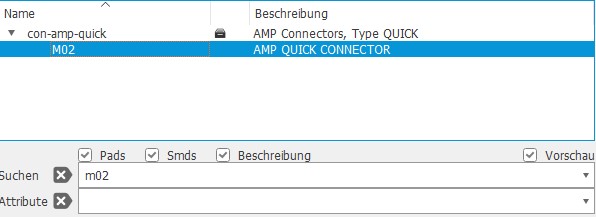
When you click it, it opens up the window below.Here you can search for whatever component you might need at the moment.
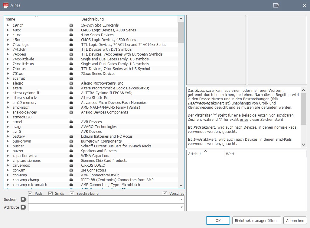
As an example let's say I wanted a 2 pin pin header, I just type "m02" into the searchbar and viola we have the part we want and can place it wherever we want on the schematic.
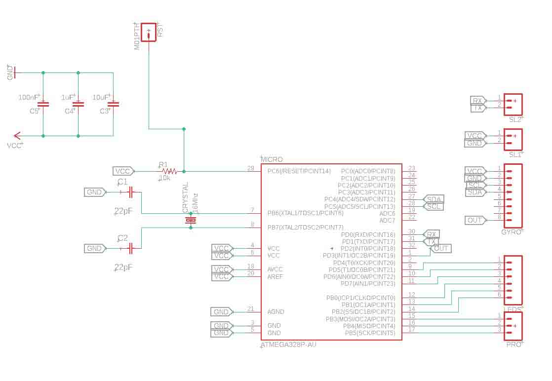
Second one is the net function, to put it simply you can draw wires with it and connect components on your schematic. It is really easy to use, just select it and left-click wherever you want a connection to be.

And lastly there is the label function, it basically does the same thing as the net tool, but in a much more tidy way. The traces don't get connected directly, but through references. So if two traces have the same label, they will be connected on the board.

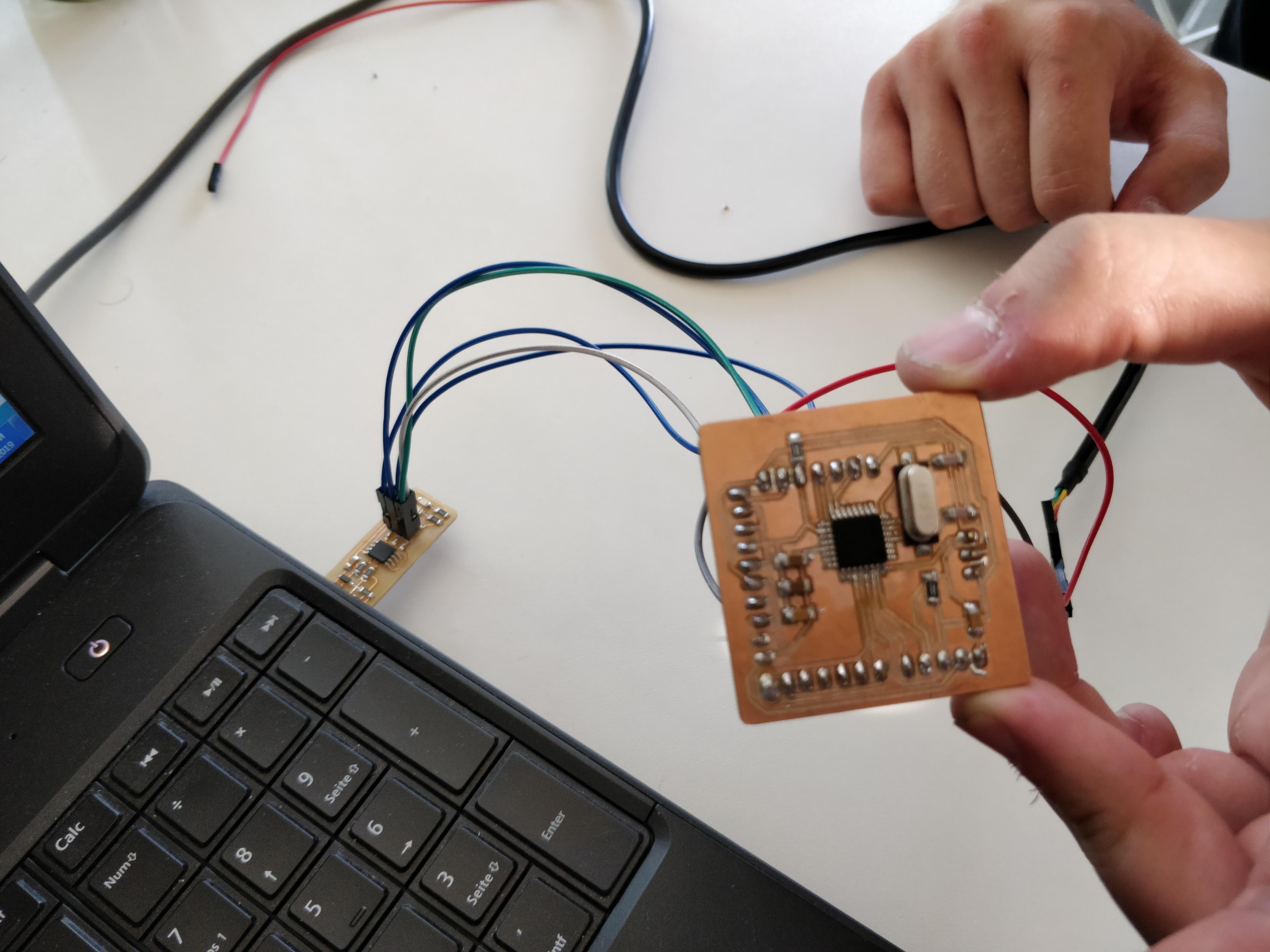
So using these tools and techniques, I came up with this simple board. All of the capacitors and the VCCs and GNDs, as well as the crystal are stated in the Datasheet of the AtMega328p and are therefore pretty much given. The only thing I did was expose the pins I would need to be able to interface with my accelerometer, a few programming pins and a button for the reset line.
I then changed into the board view and started arranging my components to take up the least amount of space on the board, while still being far enough away from each other to prevent shorts. Then I routed the traces to connect the components together. This is the tool you need to select, to create traces. Also set the width to 12, we tested that to be the best width for milling traces in our group assignment.


After you have connected up everything
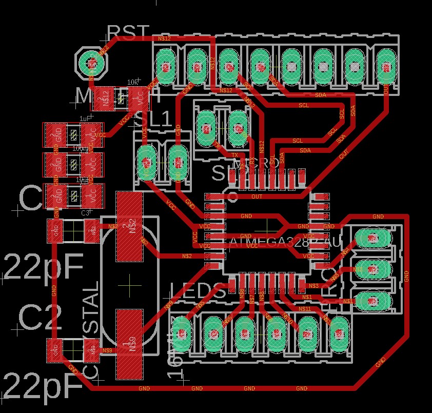
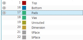
you now need to export your design. Before you do that though, turn off the visibility of every layer but these three:
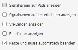
Then you can go into the settings and under "misc" deselect these checkoxes:
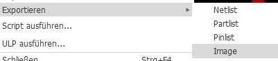
Now you can go to file - export - image
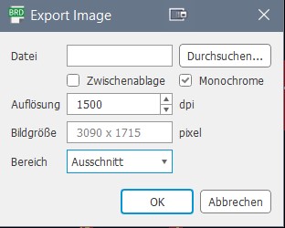
and choose monochrome, set the dpi to 1500 and set the area to "window".
This is what ypu should end up with after exporting:
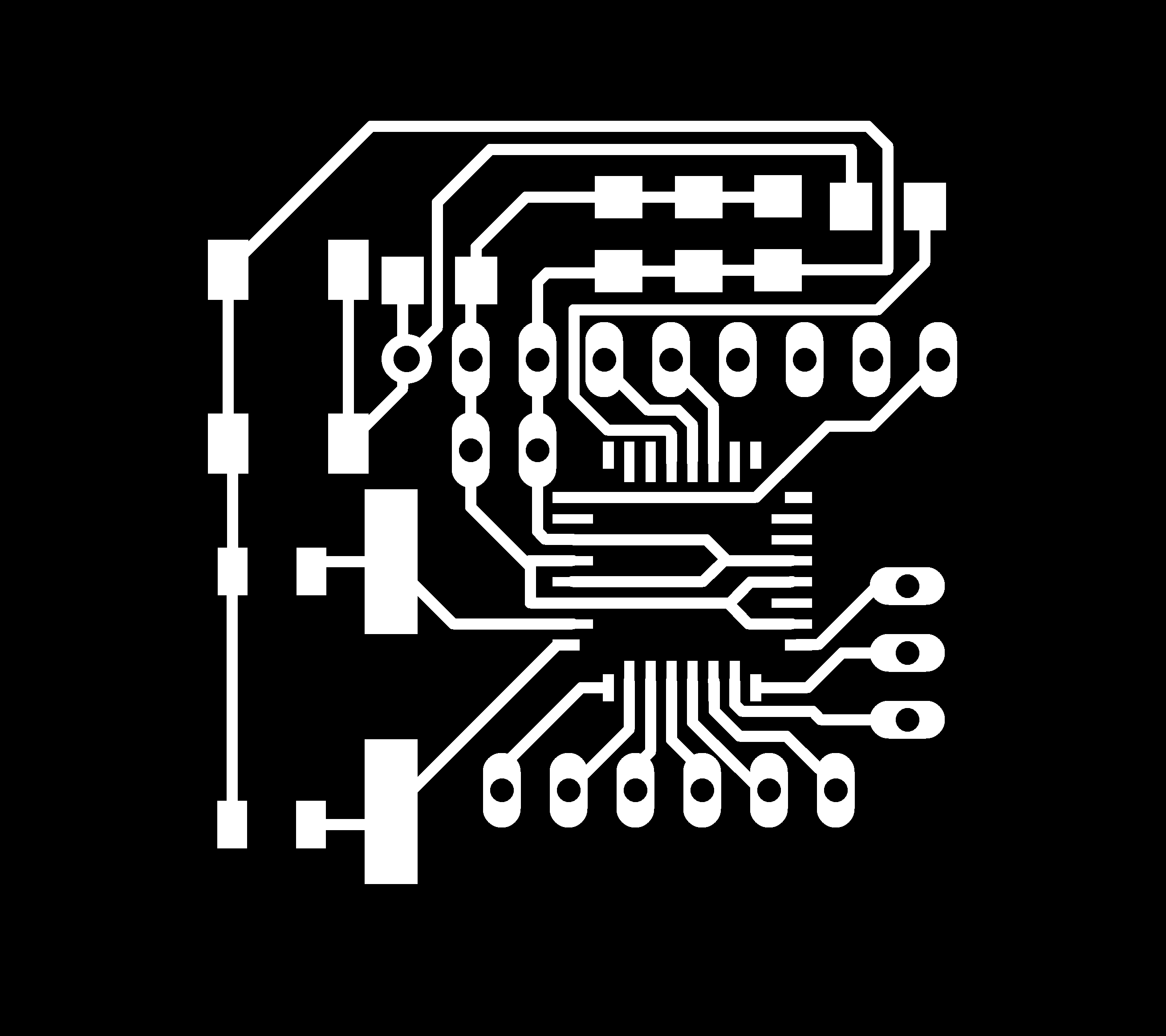
Now you can go to any raster image processing tool of your choice, open the image, draw a white polygon around it and save it as something else than the other image.
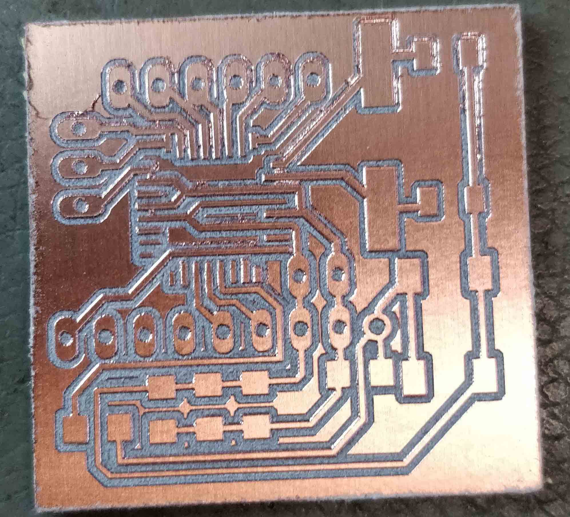
And now you are at the point, where the Electronics production assignment started off at.
After the milling process, this is what the "raw" board looked like. As you can see, it does not have any holes for the through hole components, that is because I prefer to drill these manually for no particular reason at all.
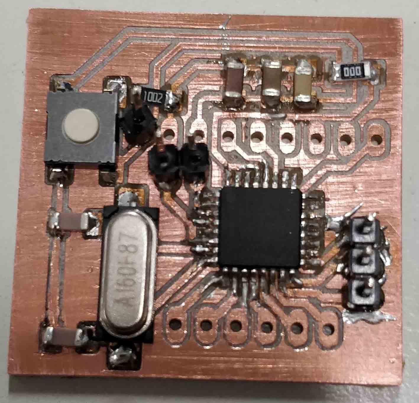
So next I drilled the holes and soldered everything to the board, I left most of the holes as they are because this is where the accelerometer and the wires for the leds are going to go. The only holes I soldered pins to are the ones I will use to program the board.
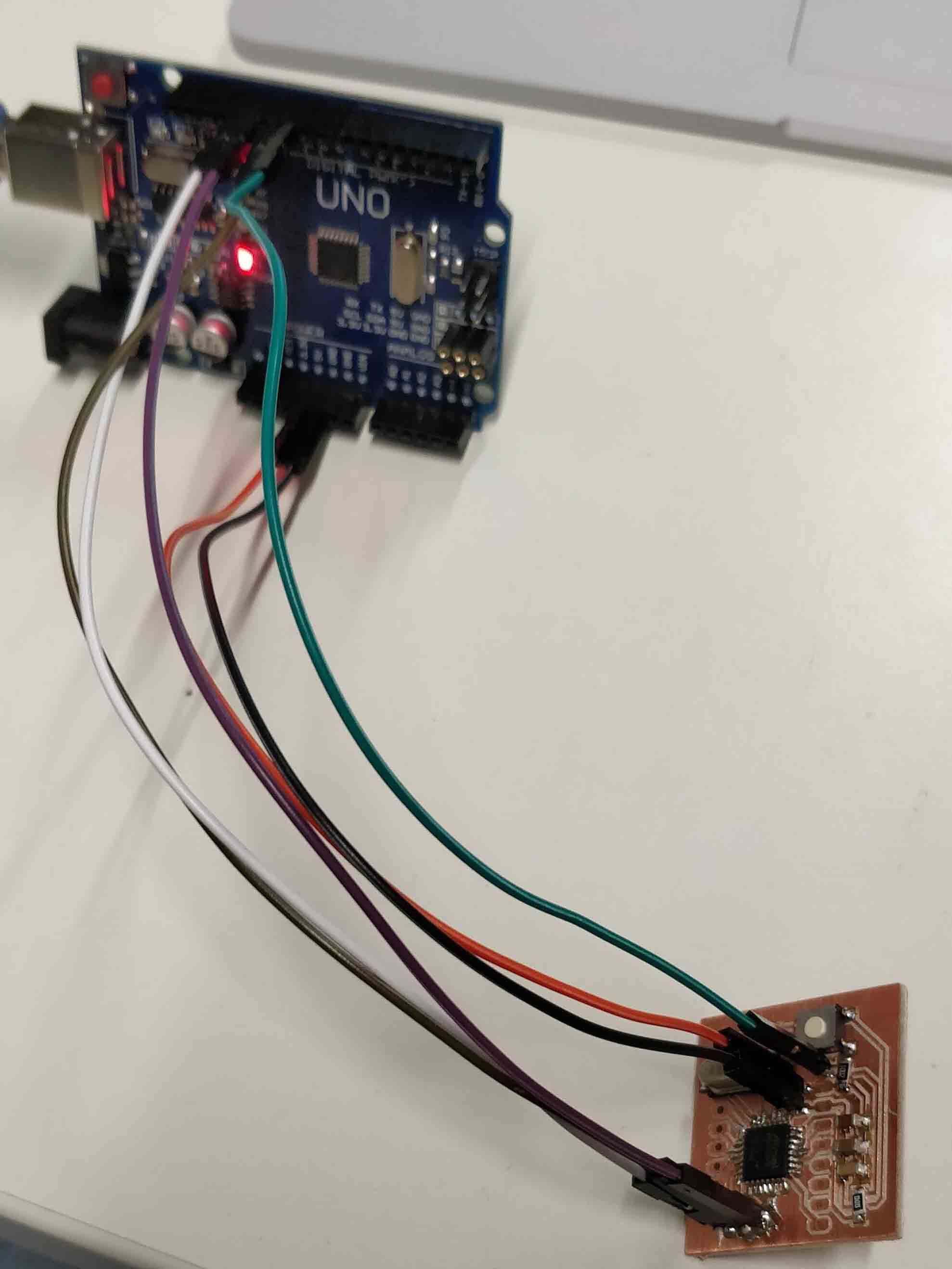
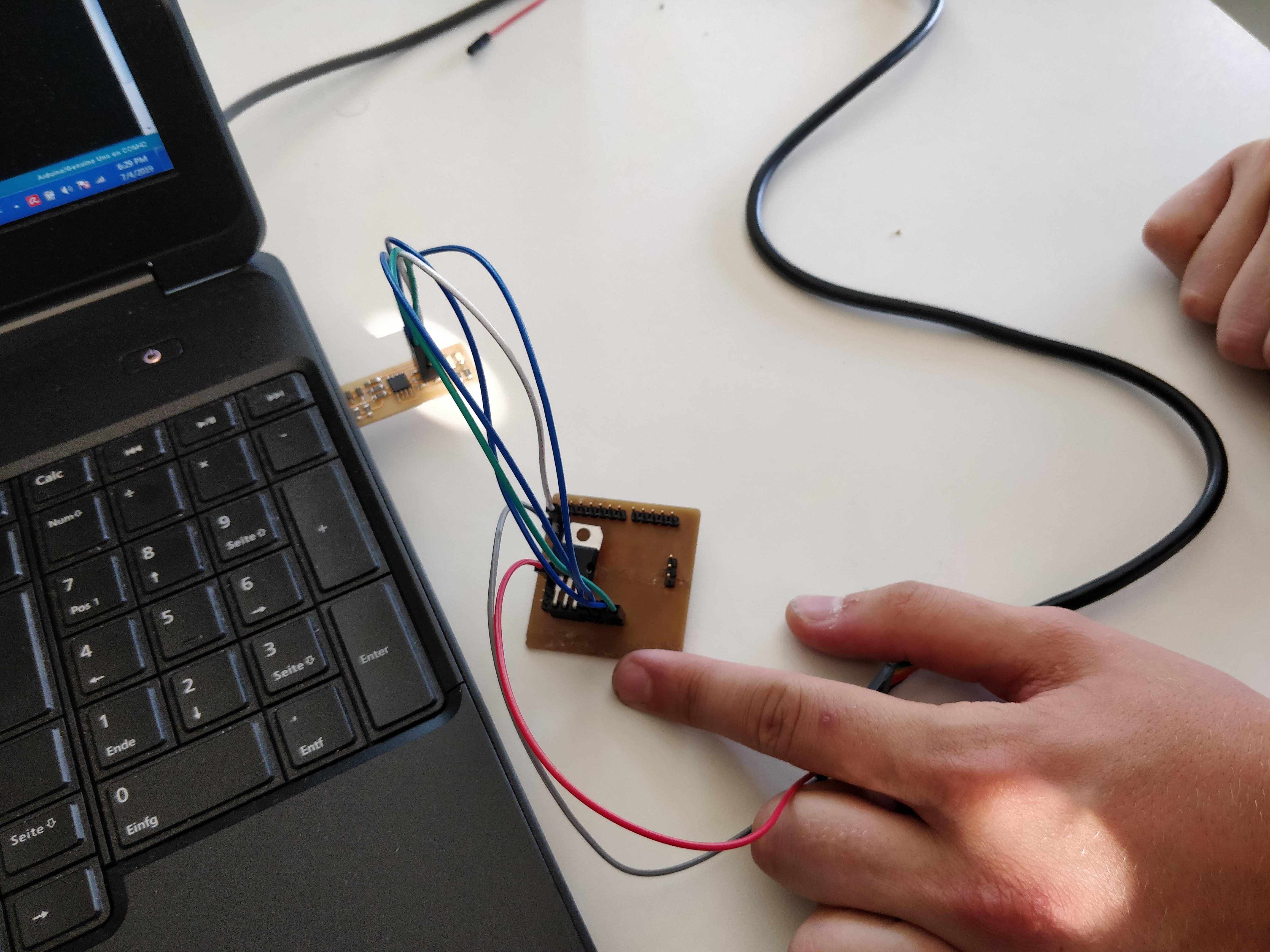
I then used my Arduino as an ISP to burn the bootloader onto my AtMega328p. This is done by connecting pins 10, 11, 12 and 13 to the board's RST, MISO, MOSI and SCK. Also the board has to be powered of course. Then I uploaded the "Arduino as ISP" sketch to my arduino by opening it under Examples - 11.ArduinoISP and clicking the upload button.
Then I changed the programmer under tools - Programmer to "Arduino as ISP", that allows me to upload code to my board when sketch - upload using programmer is clicked.
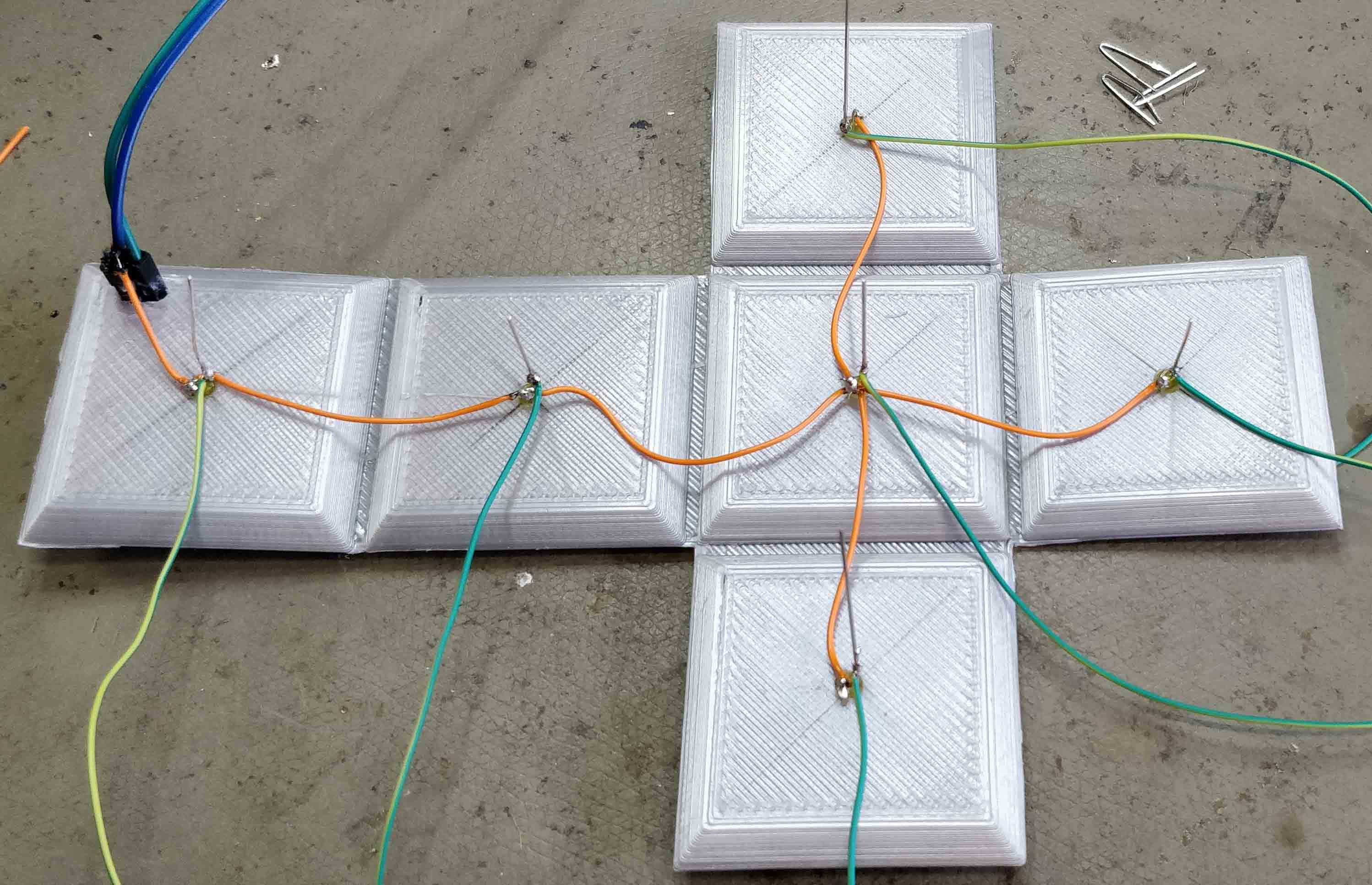
I then 3d printed a pattern, that can be heated up and bent to form a cube. I then marked the center of each of it's sides.
After that I drilled holes in the marks I made beforehand. Since I was going to use 3mm leds, I opted for a slightly smaller drillbit to make them fit snuggly.
Then I inserted a led into each of the holes amd fixed them in place with a little bit of ca-glue.
Now I connected each of the leds kathodes, because they can share a common ground. I also snipped off the overhanging part of the leds legs, because there is not much space inside the cube.
After that I drilled two more holes into the cube, to be able to get VCC and GND inside of it. Also I connected a wire to each of the leds anodes.
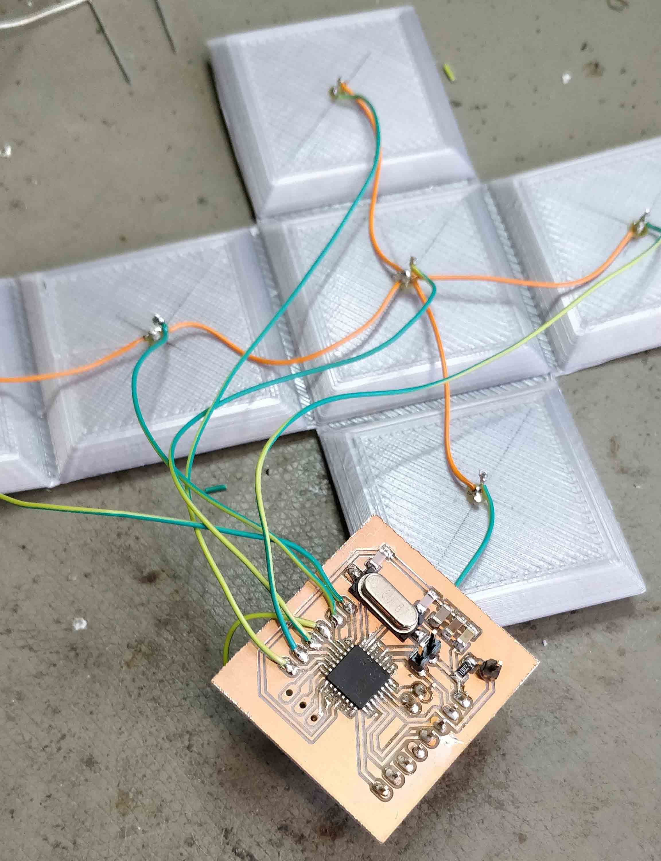
Each of those wires is now soldered directly to the board. Also the accelerometer is soldered into place.
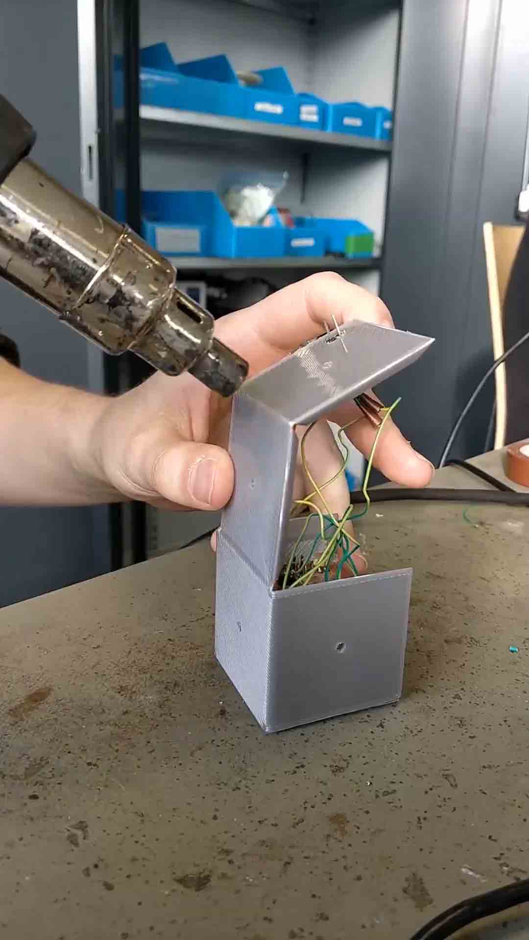
Then the Cube is bent into place using a hot air gun.
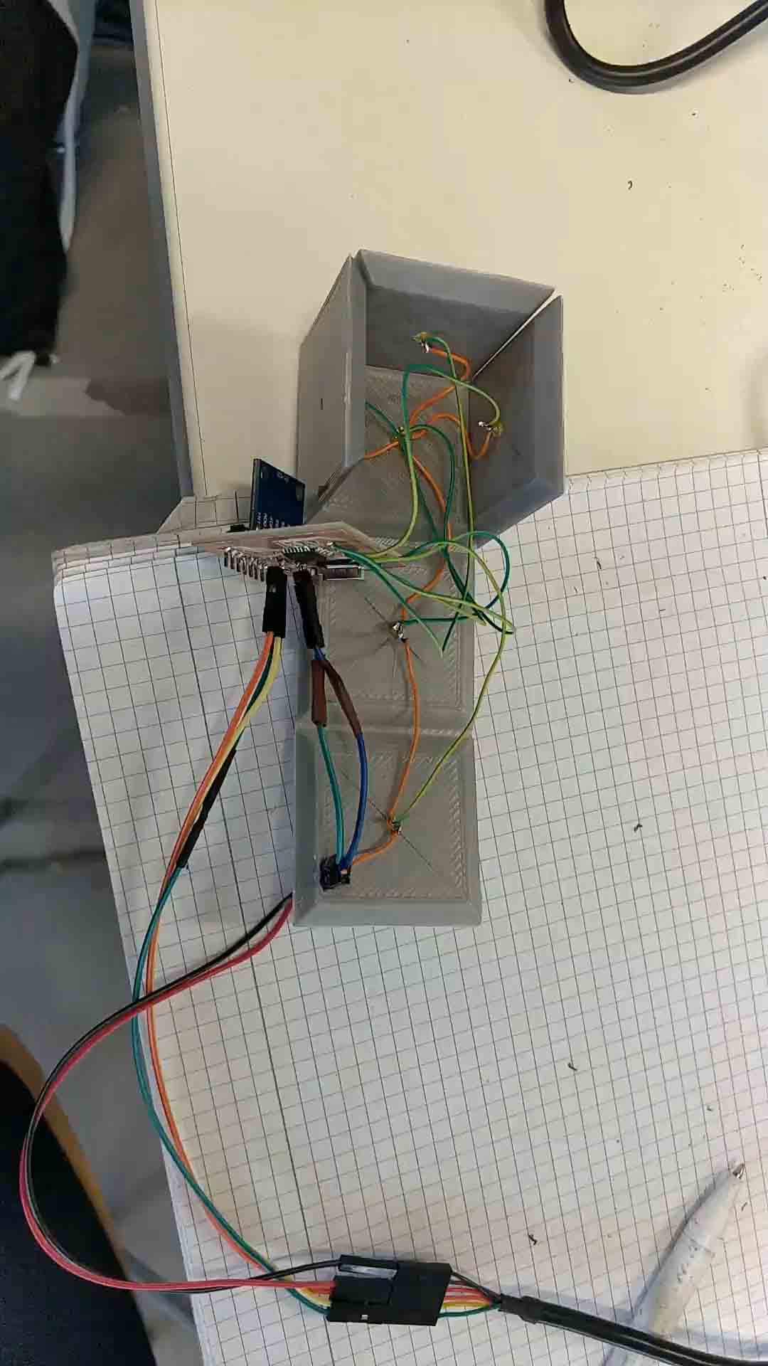
After that all of the electronics are placed inside the cube and the rest of it's sides are bent into place.
And this is the final result:
To program a board with my FabISP, I first needed to install the right drivers for it. Even though it was recognized beforehand, the arduino IDE did not recognize it as a "USBtinyISP". Therefore I had to get the latest drivers for it, which can be found on this website.
After installing these drivers, the ISP got recognized by windows without any complaints whatsoever.

Then it was just a matter of connecting the ISP to one of the boards I made in the lab. This is done using the programming pins, so :
Only the VCC had to come from an outside source, since I disconnected the jumper on my FabISP.
Then I plugged the ISP into one of my free USB-ports. In the arduino IDE I selected "USBtinyISP" as the programmer.

And that's pretty much it! I could now just click on the "burn bootloader" button and it was successful.
A little note to add is, that the ISP does not get recognized as a COM-port, which may seem weird at first, but makes sense because the computer recognized the ISP as a USBtinyISP and the arduino IDE searches for devices with that signature whenever you upload something.
And that's it, as you can see the FabISP successfully burned the bootloader on one of my boards, which confirms it is working.
download the files
So first of all, Eagle is really easy to use to make a board you basically only need 3 functions:
First is the add part function
It allows you to add components from a huge list preinstalled parts and can be augmented with downloadable libraries.
When you click it, it opens up the window below.Here you can search for whatever component you might need at the moment.
As an example let's say I wanted a 2 pin pin header, I just type "m02" into the searchbar and viola we have the part we want and can place it wherever we want on the schematic.
Second one is the net function, to put it simply you can draw wires with it and connect components on your schematic. It is really easy to use, just select it and left-click wherever you want a connection to be.
And lastly there is the label function, it basically does the same thing as the net tool, but in a much more tidy way. The traces don't get connected directly, but through references. So if two traces have the same label, they will be connected on the board.
So using these tools and techniques, I came up with this simple board. All of the capacitors and the VCCs and GNDs, as well as the crystal are stated in the Datasheet of the AtMega328p and are therefore pretty much given. The only thing I did was expose the pins I would need to be able to interface with my accelerometer, a few programming pins and a button for the reset line.
I then changed into the board view and started arranging my components to take up the least amount of space on the board, while still being far enough away from each other to prevent shorts. Then I routed the traces to connect the components together. This is the tool you need to select, to create traces. Also set the width to 12, we tested that to be the best width for milling traces in our group assignment.
After you have connected up everything
you now need to export your design. Before you do that though, turn off the visibility of every layer but these three:
Then you can go into the settings and under "misc" deselect these checkoxes:
Now you can go to file - export - image
and choose monochrome, set the dpi to 1500 and set the area to "window".
This is what ypu should end up with after exporting:
Now you can go to any raster image processing tool of your choice, open the image, draw a white polygon around it and save it as something else than the other image.
And now you are at the point, where the Electronics production assignment started off at.
After the milling process, this is what the "raw" board looked like. As you can see, it does not have any holes for the through hole components, that is because I prefer to drill these manually for no particular reason at all.
So next I drilled the holes and soldered everything to the board, I left most of the holes as they are because this is where the accelerometer and the wires for the leds are going to go. The only holes I soldered pins to are the ones I will use to program the board.
I then used my Arduino as an ISP to burn the bootloader onto my AtMega328p. This is done by connecting pins 10, 11, 12 and 13 to the board's RST, MISO, MOSI and SCK. Also the board has to be powered of course. Then I uploaded the "Arduino as ISP" sketch to my arduino by opening it under Examples - 11.ArduinoISP and clicking the upload button.
Then I changed the programmer under tools - Programmer to "Arduino as ISP", that allows me to upload code to my board when sketch - upload using programmer is clicked.
/* ============================================
I2Cdev device library code is placed under the MIT license
Copyright (c) 2012 Jeff Rowberg

Permission is hereby granted, free of charge, to any person obtaining a copy
of this software and associated documentation files (the "Software"), to deal
in the Software without restriction, including without limitation the rights
to use, copy, modify, merge, publish, distribute, sublicense, and/or sell
copies of the Software, and to permit persons to whom the Software is
furnished to do so, subject to the following conditions:

The above copyright notice and this permission notice shall be included in
all copies or substantial portions of the Software.

THE SOFTWARE IS PROVIDED "AS IS", WITHOUT WARRANTY OF ANY KIND, EXPRESS OR
IMPLIED, INCLUDING BUT NOT LIMITED TO THE WARRANTIES OF MERCHANTABILITY,
FITNESS FOR A PARTICULAR PURPOSE AND NONINFRINGEMENT. IN NO EVENT SHALL THE
AUTHORS OR COPYRIGHT HOLDERS BE LIABLE FOR ANY CLAIM, DAMAGES OR OTHER
LIABILITY, WHETHER IN AN ACTION OF CONTRACT, TORT OR OTHERWISE, ARISING FROM,
OUT OF OR IN CONNECTION WITH THE SOFTWARE OR THE USE OR OTHER DEALINGS IN
THE SOFTWARE.
===============================================
*/

#include "I2Cdev.h"

#include "MPU6050_6Axis_MotionApps20.h"
#if I2CDEV_IMPLEMENTATION == I2CDEV_ARDUINO_WIRE
    #include "Wire.h"
#endif

MPU6050 mpu;
#define OUTPUT_READABLE_YAWPITCHROLL


#define INTERRUPT_PIN 3  // use pin 2 on Arduino Uno & most boards
#define LED_PIN 13 // (Arduino is 13, Teensy is 11, Teensy++ is 6)
#define LED_PIN1 5
#define LED_PIN2 6
#define LED_PIN3 7
#define LED_PIN4 8
#define LED_PIN5 9
#define LED_PIN6 10
bool blinkState = false;

// MPU control/status vars
bool dmpReady = false;  // set true if DMP init was successful
uint8_t mpuIntStatus;   // holds actual interrupt status byte from MPU
uint8_t devStatus;      // return status after each device operation (0 = success, !0 = error)
uint16_t packetSize;    // expected DMP packet size (default is 42 bytes)
uint16_t fifoCount;     // count of all bytes currently in FIFO
uint8_t fifoBuffer[64]; // FIFO storage buffer

// orientation/motion vars
Quaternion q;           // [w, x, y, z]         quaternion container
VectorInt16 aa;         // [x, y, z]            accel sensor measurements
VectorInt16 aaReal;     // [x, y, z]            gravity-free accel sensor measurements
VectorInt16 aaWorld;    // [x, y, z]            world-frame accel sensor measurements
VectorFloat gravity;    // [x, y, z]            gravity vector
float euler[3];         // [psi, theta, phi]    Euler angle container
float ypr[3];           // [yaw, pitch, roll]   yaw/pitch/roll container and gravity vector

// packet structure for InvenSense teapot demo
uint8_t teapotPacket[14] = { '$', 0x02, 0,0, 0,0, 0,0, 0,0, 0x00, 0x00, '\r', '\n' };


// ================================================================
// ===               INTERRUPT DETECTION ROUTINE                ===
// ================================================================

volatile bool mpuInterrupt = false;     // indicates whether MPU interrupt pin has gone high
void dmpDataReady() {
    mpuInterrupt = true;
}


// ================================================================
// ===                      INITIAL SETUP                       ===
// ================================================================

void setup() {

    // join I2C bus (I2Cdev library doesn't do this automatically)
    #if I2CDEV_IMPLEMENTATION == I2CDEV_ARDUINO_WIRE
        Wire.begin();
        Wire.setClock(400000); // 400kHz I2C clock. Comment this line if having compilation difficulties
    #elif I2CDEV_IMPLEMENTATION == I2CDEV_BUILTIN_FASTWIRE
        Fastwire::setup(400, true);
    #endif

    // initialize serial communication
    // (115200 chosen because it is required for Teapot Demo output, but it's
    // really up to you depending on your project)
    Serial.begin(38400);
    while (!Serial); // wait for Leonardo enumeration, others continue immediately

    // NOTE: 8MHz or slower host processors, like the Teensy @ 3.3V or Arduino
    // Pro Mini running at 3.3V, cannot handle this baud rate reliably due to
    // the baud timing being too misaligned with processor ticks. You must use
    // 38400 or slower in these cases, or use some kind of external separate
    // crystal solution for the UART timer.

    // initialize device
    Serial.println(F("Initializing I2C devices..."));
    mpu.initialize();
    pinMode(INTERRUPT_PIN, INPUT);

    // verify connection
    Serial.println(F("Testing device connections..."));
    Serial.println(mpu.testConnection() ? F("MPU6050 connection successful") : F("MPU6050 connection failed"));

    // wait for ready
    /*Serial.println(F("\nSend any character to begin DMP programming and demo: "));
    while (Serial.available() && Serial.read()); // empty buffer
    while (!Serial.available());                 // wait for data
    while (Serial.available() && Serial.read()); // empty buffer again
*/
    // load and configure the DMP
    Serial.println(F("Initializing DMP..."));
    devStatus = mpu.dmpInitialize();

    // supply your own gyro offsets here, scaled for min sensitivity
    mpu.setXGyroOffset(220);
    mpu.setYGyroOffset(76);
    mpu.setZGyroOffset(-85);
    mpu.setZAccelOffset(1788); // 1688 factory default for my test chip

    // make sure it worked (returns 0 if so)
    if (devStatus == 0) {
        // turn on the DMP, now that it's ready
        Serial.println(F("Enabling DMP..."));
        mpu.setDMPEnabled(true);

        // enable Arduino interrupt detection
        Serial.print(F("Enabling interrupt detection (Arduino external interrupt "));
        Serial.print(digitalPinToInterrupt(INTERRUPT_PIN));
        Serial.println(F(")..."));
        attachInterrupt(digitalPinToInterrupt(INTERRUPT_PIN), dmpDataReady, RISING);
        mpuIntStatus = mpu.getIntStatus();

        // set our DMP Ready flag so the main loop() function knows it's okay to use it
        Serial.println(F("DMP ready! Waiting for first interrupt..."));
        dmpReady = true;

        // get expected DMP packet size for later comparison
        packetSize = mpu.dmpGetFIFOPacketSize();
    } else {
        // ERROR!
        // 1 = initial memory load failed
        // 2 = DMP configuration updates failed
        // (if it's going to break, usually the code will be 1)
        Serial.print(F("DMP Initialization failed (code "));
        Serial.print(devStatus);
        Serial.println(F(")"));
    }

    // configure LED for output
    pinMode(LED_PIN1,OUTPUT);
    pinMode(LED_PIN2,OUTPUT);
    pinMode(LED_PIN3,OUTPUT);
    pinMode(LED_PIN4,OUTPUT);
    pinMode(LED_PIN5,OUTPUT);
    pinMode(LED_PIN6,OUTPUT);
    pinMode(LED_PIN, OUTPUT);
}


// ================================================================
// ===                    MAIN PROGRAM LOOP                     ===
// ================================================================

void loop() {
    // if programming failed, don't try to do anything
    if (!dmpReady) return;

    // wait for MPU interrupt or extra packet(s) available
    while (!mpuInterrupt && fifoCount < packetSize) {
        if (mpuInterrupt && fifoCount < packetSize) {
          // try to get out of the infinite loop
          fifoCount = mpu.getFIFOCount();
        }
        // other program behavior stuff here
        // .
        // .
        // .
        // if you are really paranoid you can frequently test in between other
        // stuff to see if mpuInterrupt is true, and if so, "break;" from the
        // while() loop to immediately process the MPU data
        // .
        // .
        // .
    }

    // reset interrupt flag and get INT_STATUS byte
    mpuInterrupt = false;
    mpuIntStatus = mpu.getIntStatus();

    // get current FIFO count
    fifoCount = mpu.getFIFOCount();

    // check for overflow (this should never happen unless our code is too inefficient)
    if ((mpuIntStatus & _BV(MPU6050_INTERRUPT_FIFO_OFLOW_BIT)) || fifoCount >= 1024) {
        // reset so we can continue cleanly
        mpu.resetFIFO();
        fifoCount = mpu.getFIFOCount();
        Serial.println(F("FIFO overflow!"));

    // otherwise, check for DMP data ready interrupt (this should happen frequently)
    } else if (mpuIntStatus & _BV(MPU6050_INTERRUPT_DMP_INT_BIT)) {
        // wait for correct available data length, should be a VERY short wait
        while (fifoCount < packetSize) fifoCount = mpu.getFIFOCount();

        // read a packet from FIFO
        mpu.getFIFOBytes(fifoBuffer, packetSize);

        // track FIFO count here in case there is > 1 packet available
        // (this lets us immediately read more without waiting for an interrupt)
        fifoCount -= packetSize;

        #ifdef OUTPUT_READABLE_YAWPITCHROLL
            // display Euler angles in degrees
            mpu.dmpGetQuaternion(&q, fifoBuffer);
            mpu.dmpGetGravity(&gravity, &q);
            mpu.dmpGetYawPitchRoll(ypr, &q, &gravity);
            if(ypr[1] * 180/M_PI < 30 && ypr[1] * 180/M_PI > (-30) && ypr[2] * 180/M_PI < (-30) && ypr[2] * 180/M_PI > (-90)){
              digitalWrite(LED_PIN1,HIGH);
              digitalWrite(LED_PIN2,LOW);
              digitalWrite(LED_PIN3,LOW);
              digitalWrite(LED_PIN4,LOW);
              digitalWrite(LED_PIN5,LOW);
              digitalWrite(LED_PIN6,LOW);
            }else if(ypr[1] * 180/M_PI < 200 && ypr[1] * 180/M_PI > (140) && ypr[2] * 180/M_PI < (-140) && ypr[2] * 180/M_PI > (-200)){
              digitalWrite(LED_PIN3,HIGH);
              digitalWrite(LED_PIN1,LOW);
              digitalWrite(LED_PIN2,LOW);
              digitalWrite(LED_PIN4,LOW);
              digitalWrite(LED_PIN5,LOW);
              digitalWrite(LED_PIN6,LOW);
            }else if(ypr[1] * 180/M_PI < -30 && ypr[1] * 180/M_PI > (-90) && ypr[2] * 180/M_PI < (30) && ypr[2] * 180/M_PI > (-20)){
              digitalWrite(LED_PIN2,HIGH);
              digitalWrite(LED_PIN1,LOW);
              digitalWrite(LED_PIN3,LOW);
              digitalWrite(LED_PIN4,LOW);
              digitalWrite(LED_PIN5,LOW);
              digitalWrite(LED_PIN6,LOW);
            }else if(ypr[1] * 180/M_PI < 30 && ypr[1] * 180/M_PI > (-30) && ypr[2] * 180/M_PI < (30) && ypr[2] * 180/M_PI > (-20)){
              digitalWrite(LED_PIN6,HIGH);
              digitalWrite(LED_PIN1,LOW);
              digitalWrite(LED_PIN2,LOW);
              digitalWrite(LED_PIN3,LOW);
              digitalWrite(LED_PIN4,LOW);
              digitalWrite(LED_PIN5,LOW);
            }else if(ypr[1] * 180/M_PI < 90 && ypr[1] * 180/M_PI > (30) && ypr[2] * 180/M_PI < (30) && ypr[2] * 180/M_PI > (-20)){
              digitalWrite(LED_PIN5,HIGH);
              digitalWrite(LED_PIN1,LOW);
              digitalWrite(LED_PIN2,LOW);
              digitalWrite(LED_PIN3,LOW);
              digitalWrite(LED_PIN4,LOW);
              digitalWrite(LED_PIN6,LOW);
            }else if(ypr[1] * 180/M_PI < 30 && ypr[1] * 180/M_PI > (-30) && ypr[2] * 180/M_PI < (90) && ypr[2] * 180/M_PI > (40)){
              digitalWrite(LED_PIN4,HIGH);
              digitalWrite(LED_PIN1,LOW);
              digitalWrite(LED_PIN2,LOW);
              digitalWrite(LED_PIN3,LOW);
              digitalWrite(LED_PIN5,LOW);
              digitalWrite(LED_PIN6,LOW);
            }else{
              digitalWrite(LED_PIN1,LOW);
              digitalWrite(LED_PIN2,LOW);
              digitalWrite(LED_PIN3,LOW);
              digitalWrite(LED_PIN4,LOW);
              digitalWrite(LED_PIN5,LOW);
              digitalWrite(LED_PIN6,LOW);
            }
        #endif


        // blink LED to indicate activity
        blinkState = !blinkState;
        digitalWrite(LED_PIN, blinkState);
    }
}
I then 3d printed a pattern, that can be heated up and bent to form a cube. I then marked the center of each of it's sides.
After that I drilled holes in the marks I made beforehand. Since I was going to use 3mm leds, I opted for a slightly smaller drillbit to make them fit snuggly.
Then I inserted a led into each of the holes amd fixed them in place with a little bit of ca-glue.
Now I connected each of the leds kathodes, because they can share a common ground. I also snipped off the overhanging part of the leds legs, because there is not much space inside the cube.
After that I drilled two more holes into the cube, to be able to get VCC and GND inside of it. Also I connected a wire to each of the leds anodes.
Each of those wires is now soldered directly to the board. Also the accelerometer is soldered into place.
Then the Cube is bent into place using a hot air gun.
After that all of the electronics are placed inside the cube and the rest of it's sides are bent into place.
And this is the final result:
FabISP programming
To program a board with my FabISP, I first needed to install the right drivers for it. Even though it was recognized beforehand, the arduino IDE did not recognize it as a "USBtinyISP". Therefore I had to get the latest drivers for it, which can be found on this website.
After installing these drivers, the ISP got recognized by windows without any complaints whatsoever.
Then it was just a matter of connecting the ISP to one of the boards I made in the lab. This is done using the programming pins, so :
- SCK - SCK
- MISO - MISO
- MOSI - MOSI
- RST - RST
- GND - GND
Only the VCC had to come from an outside source, since I disconnected the jumper on my FabISP.
Then I plugged the ISP into one of my free USB-ports. In the arduino IDE I selected "USBtinyISP" as the programmer.
And that's pretty much it! I could now just click on the "burn bootloader" button and it was successful.
A little note to add is, that the ISP does not get recognized as a COM-port, which may seem weird at first, but makes sense because the computer recognized the ISP as a USBtinyISP and the arduino IDE searches for devices with that signature whenever you upload something.
And that's it, as you can see the FabISP successfully burned the bootloader on one of my boards, which confirms it is working.
Group Assignment
Here you can find this week's group assignment.download the files