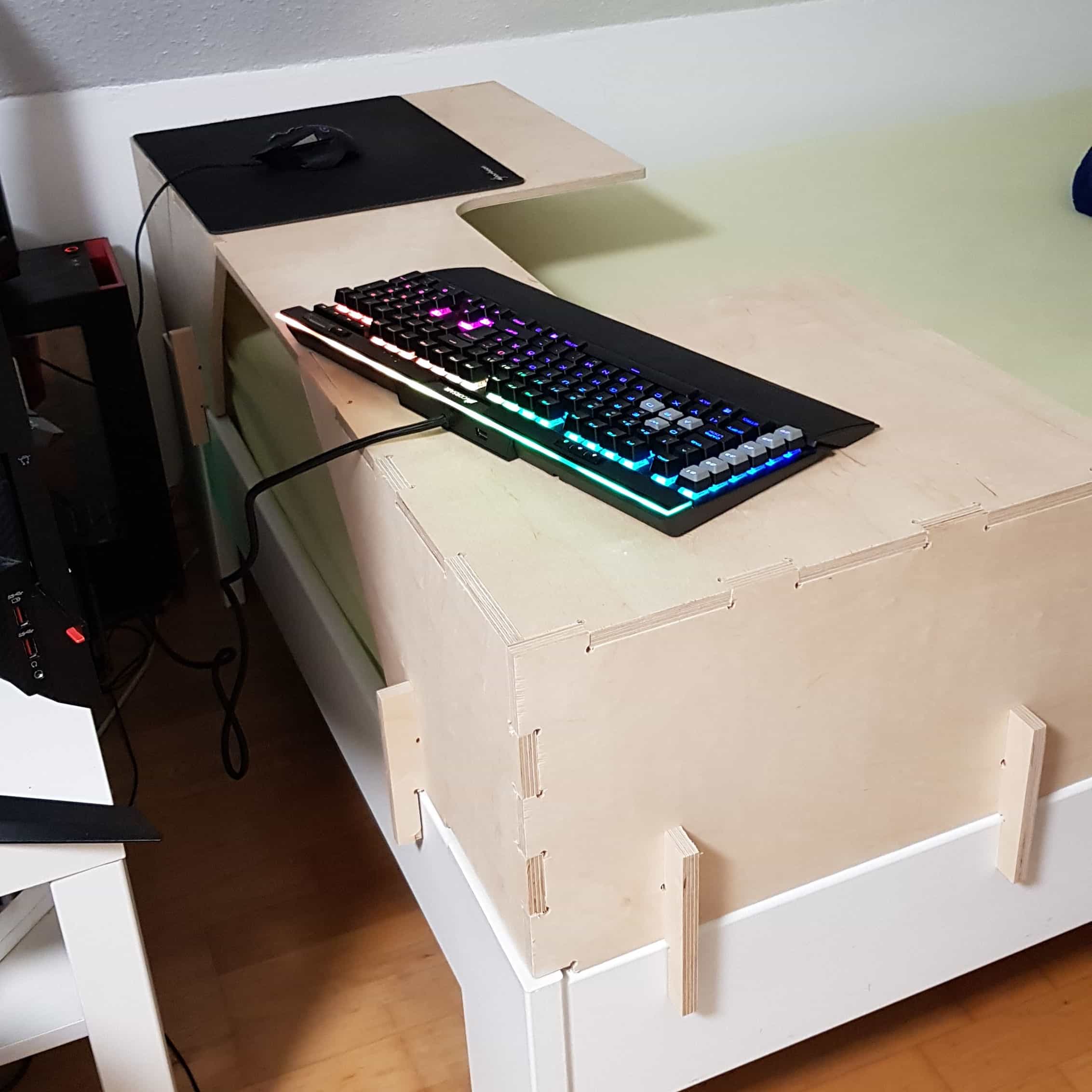
In this weeks assignment, I had the task to create something big using the cnc-machine. The assignment required designing and cutting, so I decided to make a desk for my bed.
The background story of my idea goes back a while. A few years ago I decided to change my desk to a couch in my room. But since I had a desk computer that I would never change for a laptop, I've decided to put my computer and my monitors in front of my bed, so that I could turn my bed into my desk. Now after a few years I have realized that dont having a table for your mouse and keyboard sucks. So I came to the idea to create a desk that I can stick onto my bed so that I have have both a bed and a desk.
I have worked with fusion360, a 2d/3d modeling software. If you would like to have a quick introduction into fusion check my 3rd week's assignment
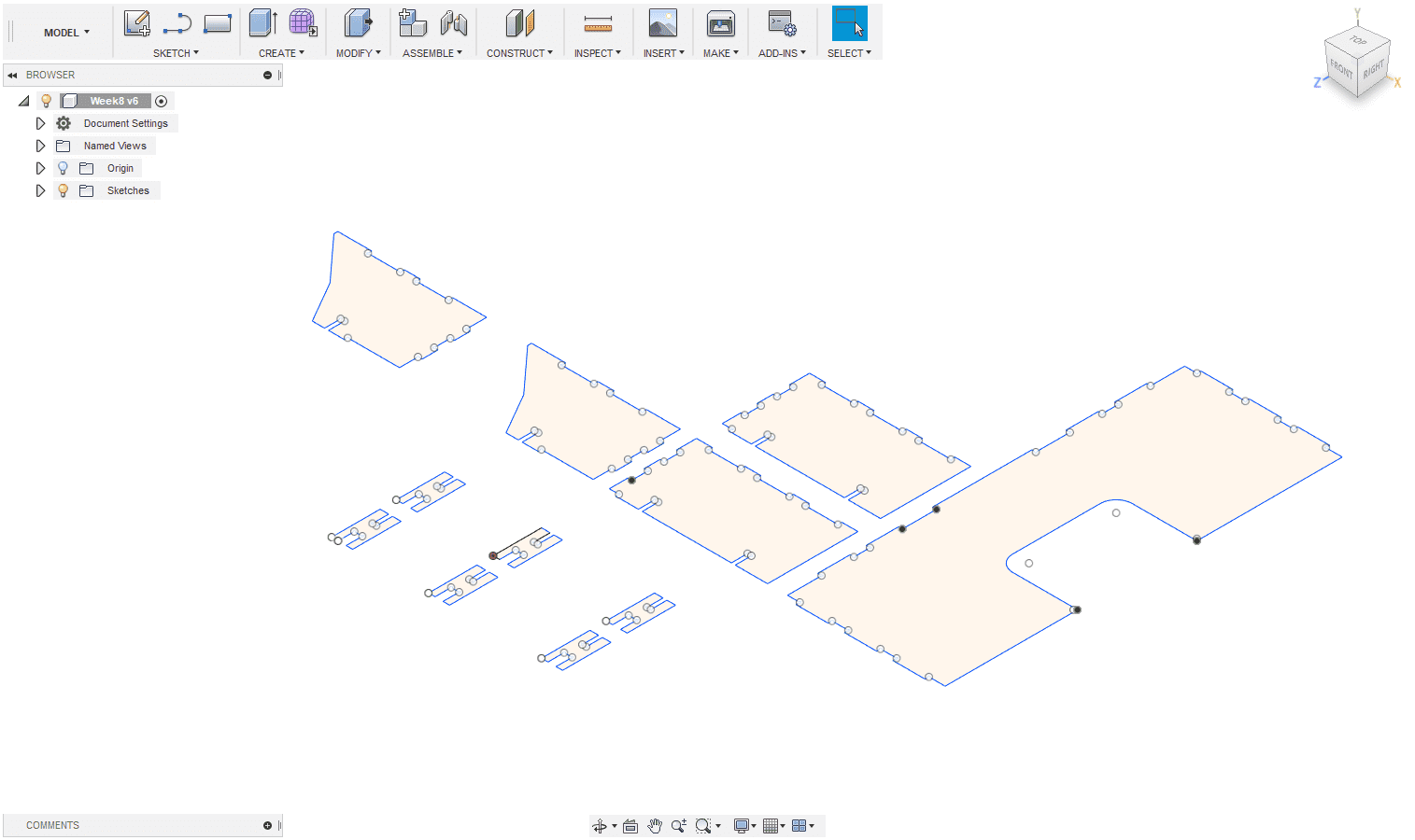
The difficult part of my design was, that I had to adjust the sizement of the table to my bedframe. So I took the measurements of my bedframe to create a 2d model in fusion.
Note that I had to put circles on every edge whicht is inside of the model because the tool I will use has a diameter of 3mm and will not be able to make a straight edge. To be honest I did not tested the joints before but this is only because of the cnc machine in our fablab is very precise and has no tolerance
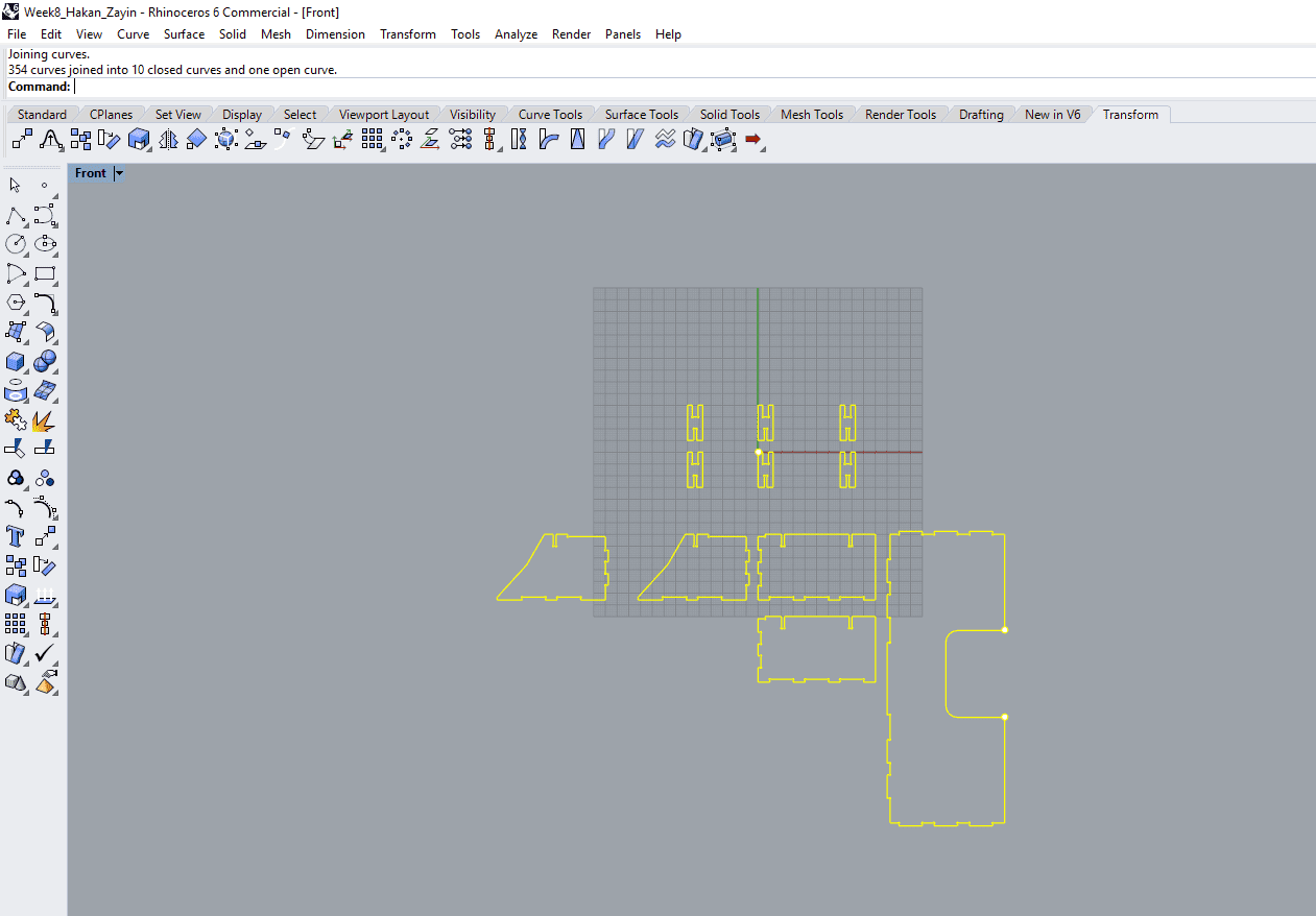
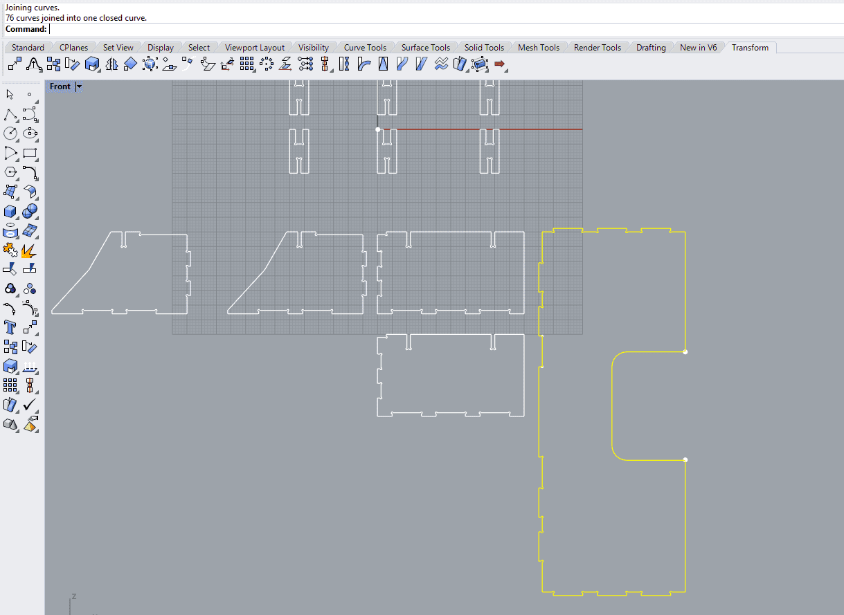
I exported my design as a .dxf file, because the cnc-machine needs a .dxf file to create the g-code. It's possible to create the g-code in fusion360 too, but I preffered to create it within the software of the cnc-machine. Before I was able to create the g-code I had to make sure that every part insists of single lines. So I openend my .dxf in rhinoceros 5. Inside rhino, I have selected everything and joined them using the join tool at the left toolbar.
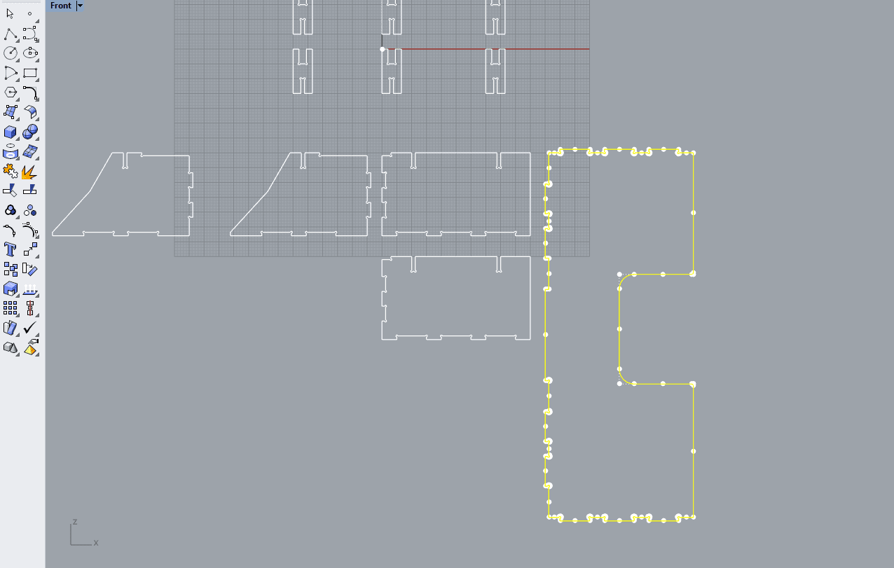
At the top bar rhino says that all the curves were joined into ten closed and one open curve. That is a problem, because I will need every curve to be closed, so that the cnc mill has no problems calculating the gcode. one open curve means that there is a line too much somewhere, to find this line I have a simple way. I just start with selecting a curve
Then I break this curve into lines again using the explode tool just beside the join tool. Now I simply join them again too see if the open curve is in this part. To see in the top bar this curve isn't the problem, because it says that it was closed into one curve.
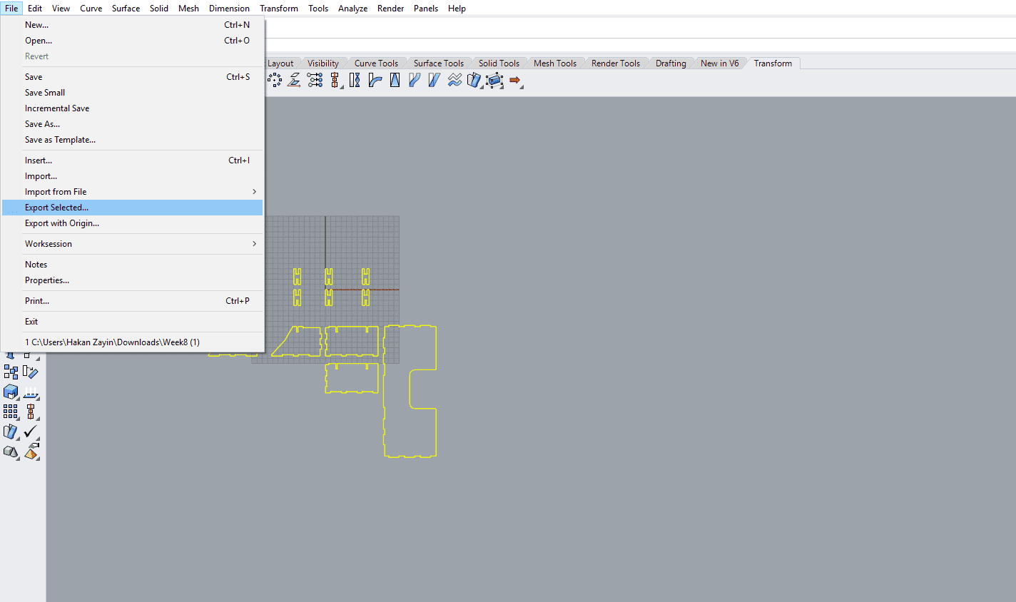
After repeating these steps with every part, I have found the problem it was a line that I made mistakely. Now after every curve is closed, I am ready to export it as a .dxf again using "Export selected".
Attention: After exporting the dxf file, dont open the exported file again because it will break the curves again so you have to repeat the steps again. Only open it when your are in the cnc software.
CNC-MACHINE
Starting to work with the cnc machine requires an safety introduction to the machine. Please never use a cnc machine when you dont have this introduction it could lead to fire, damage or even death.
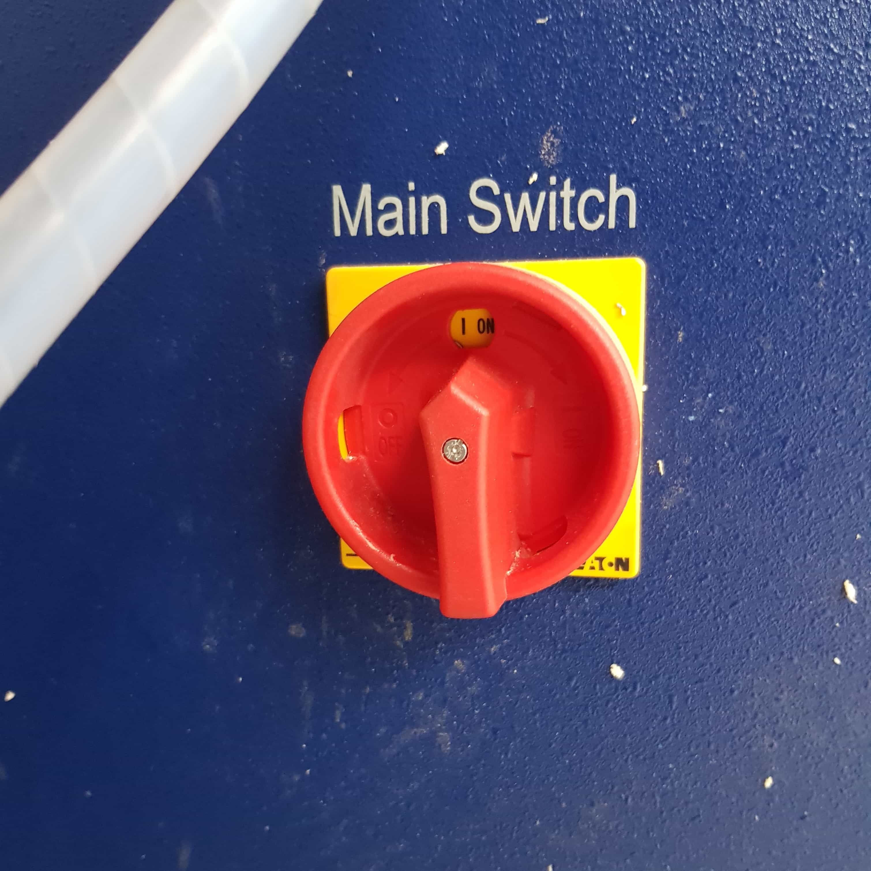
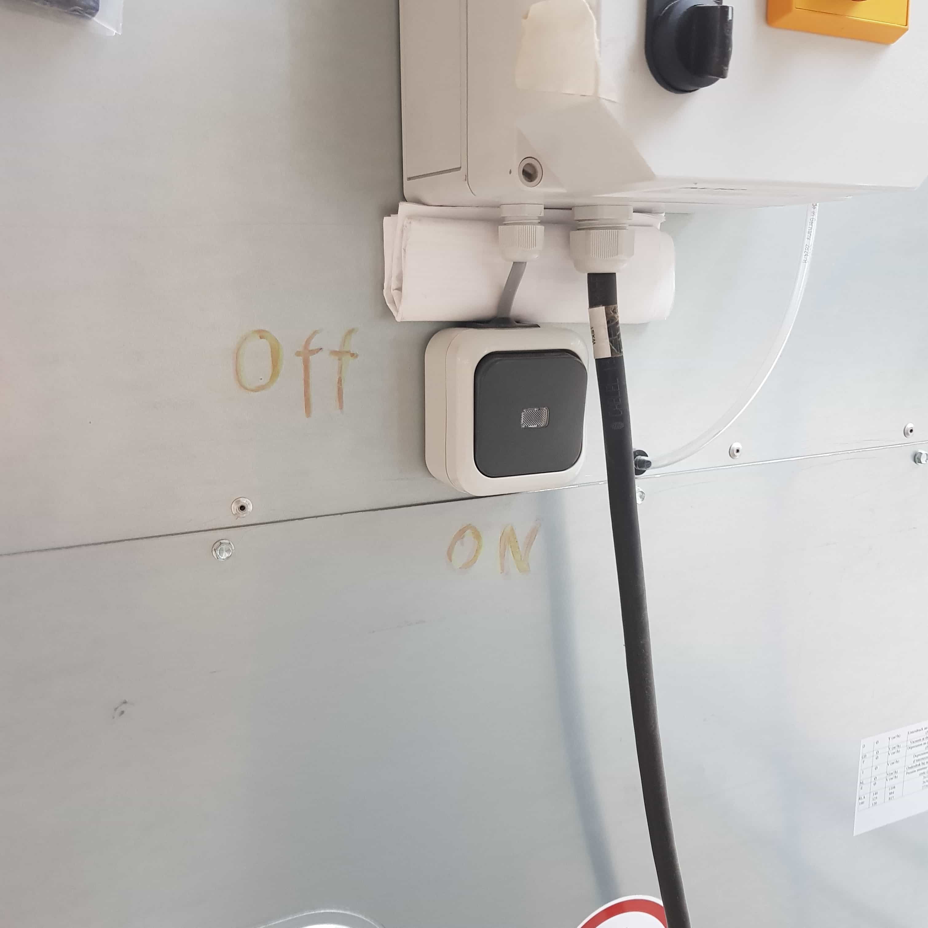
The first thing to do is mainly to start the computer which is connected to the machine, in my case I also had to turn on a main switch on the computer box and then start the computer.
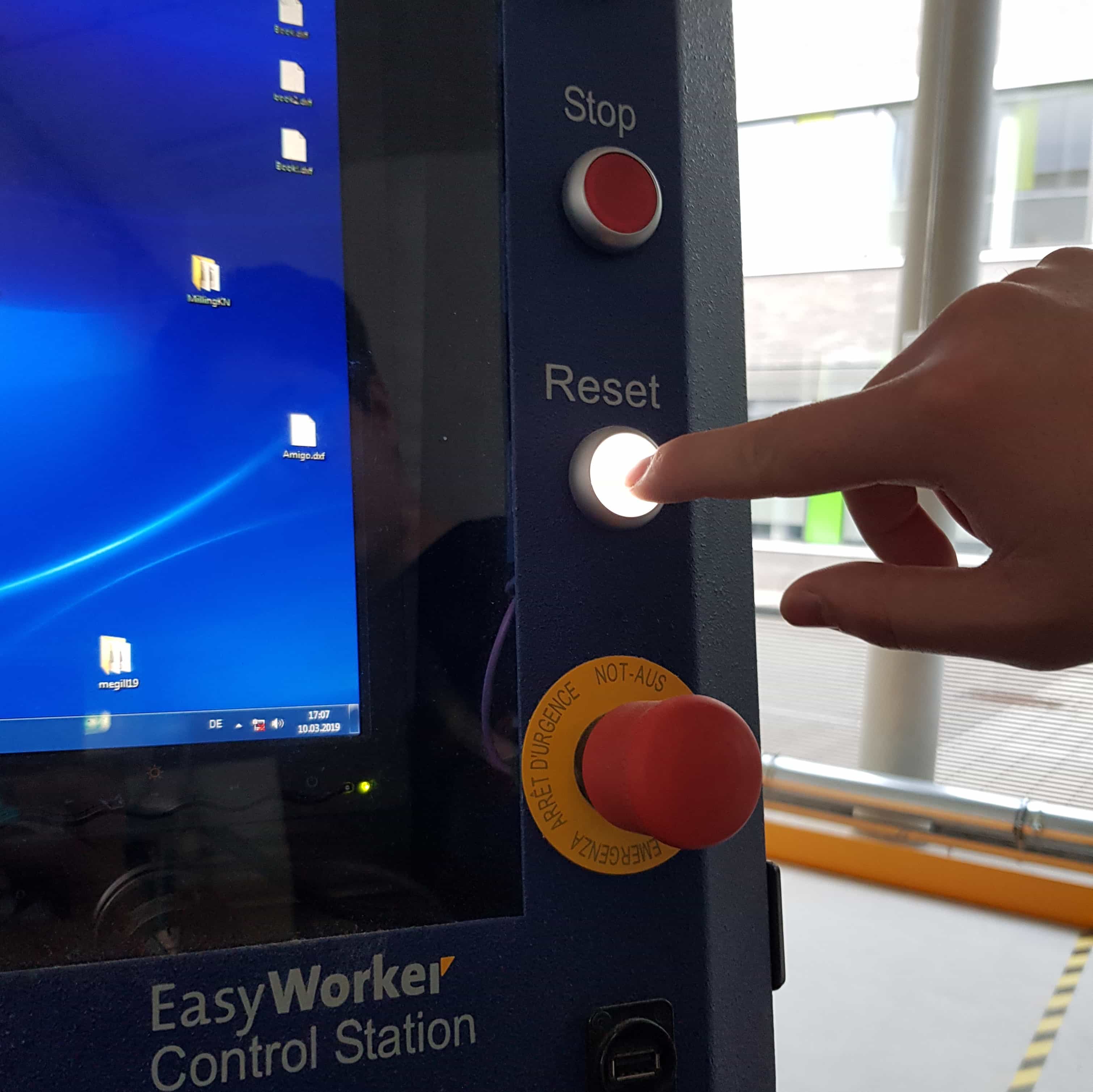
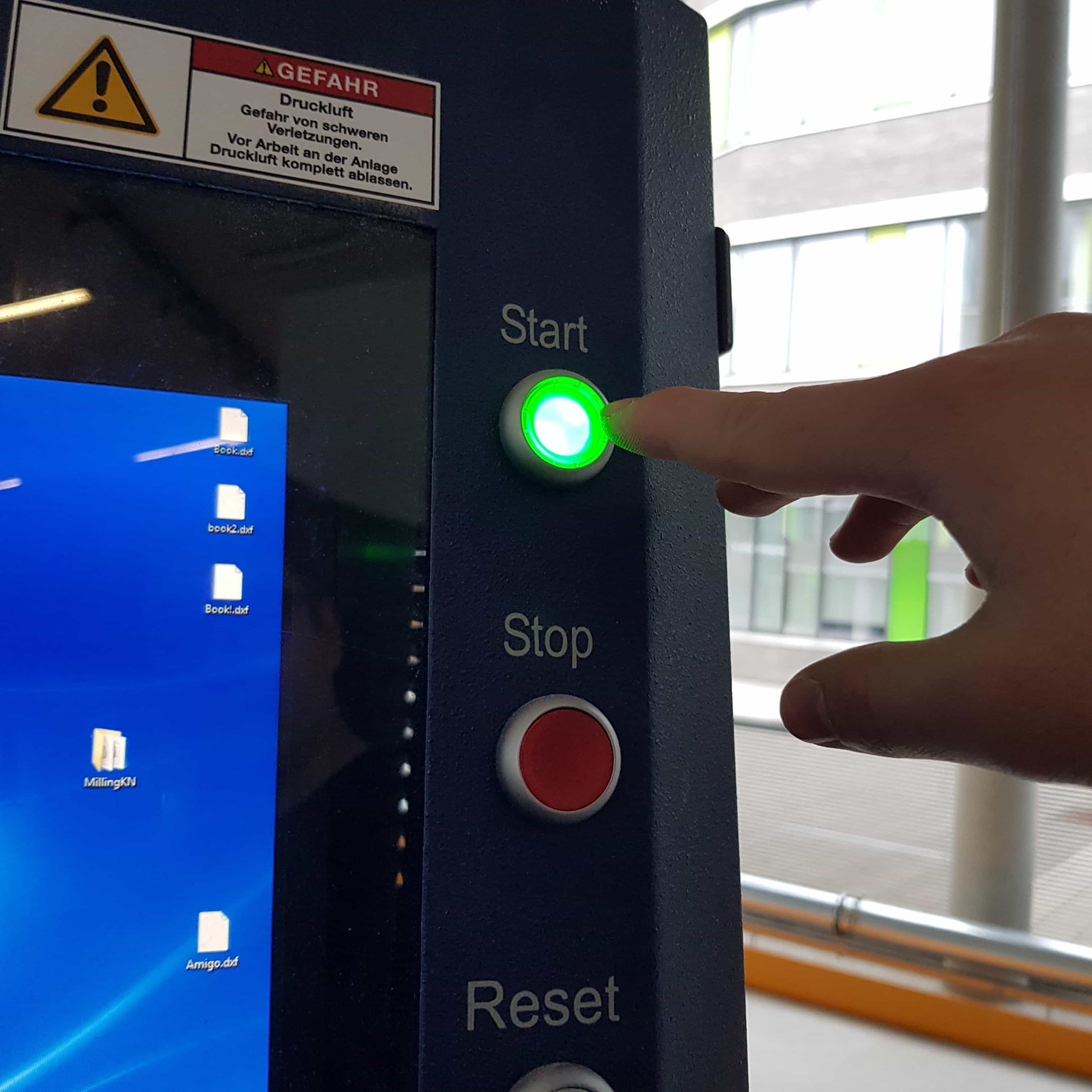
When the pc is started, I had to first press the reset
and then the start button of the cnc machine.
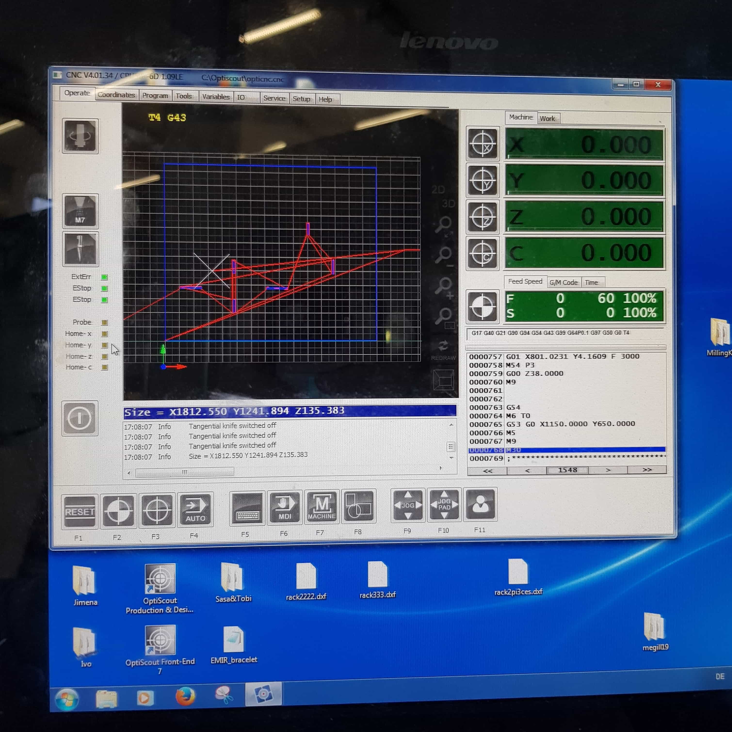
When starting the software, I got to the homescreen and the first thing I had to do was homing the cnc machine.
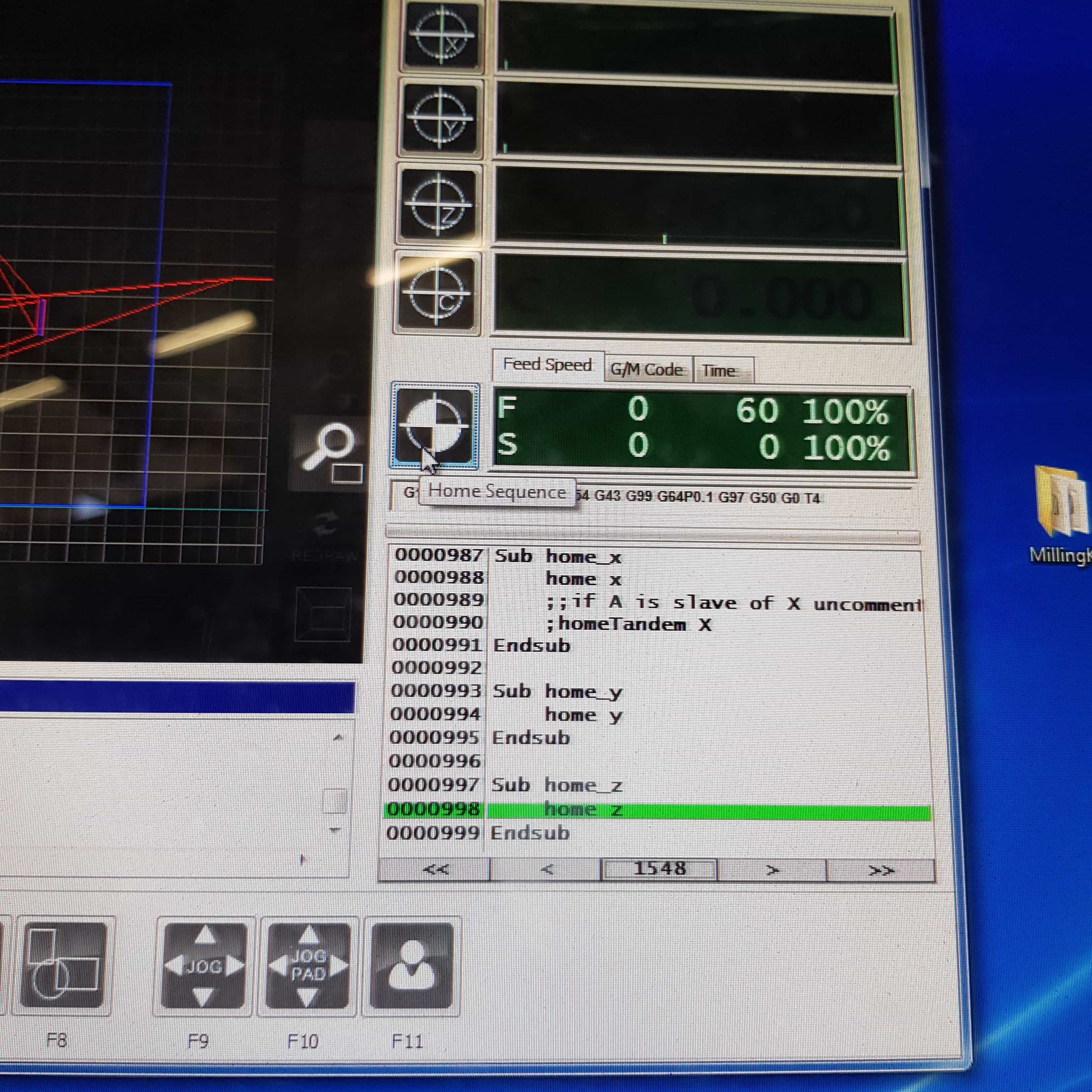
Simply pressing on the home button will start the sequence.
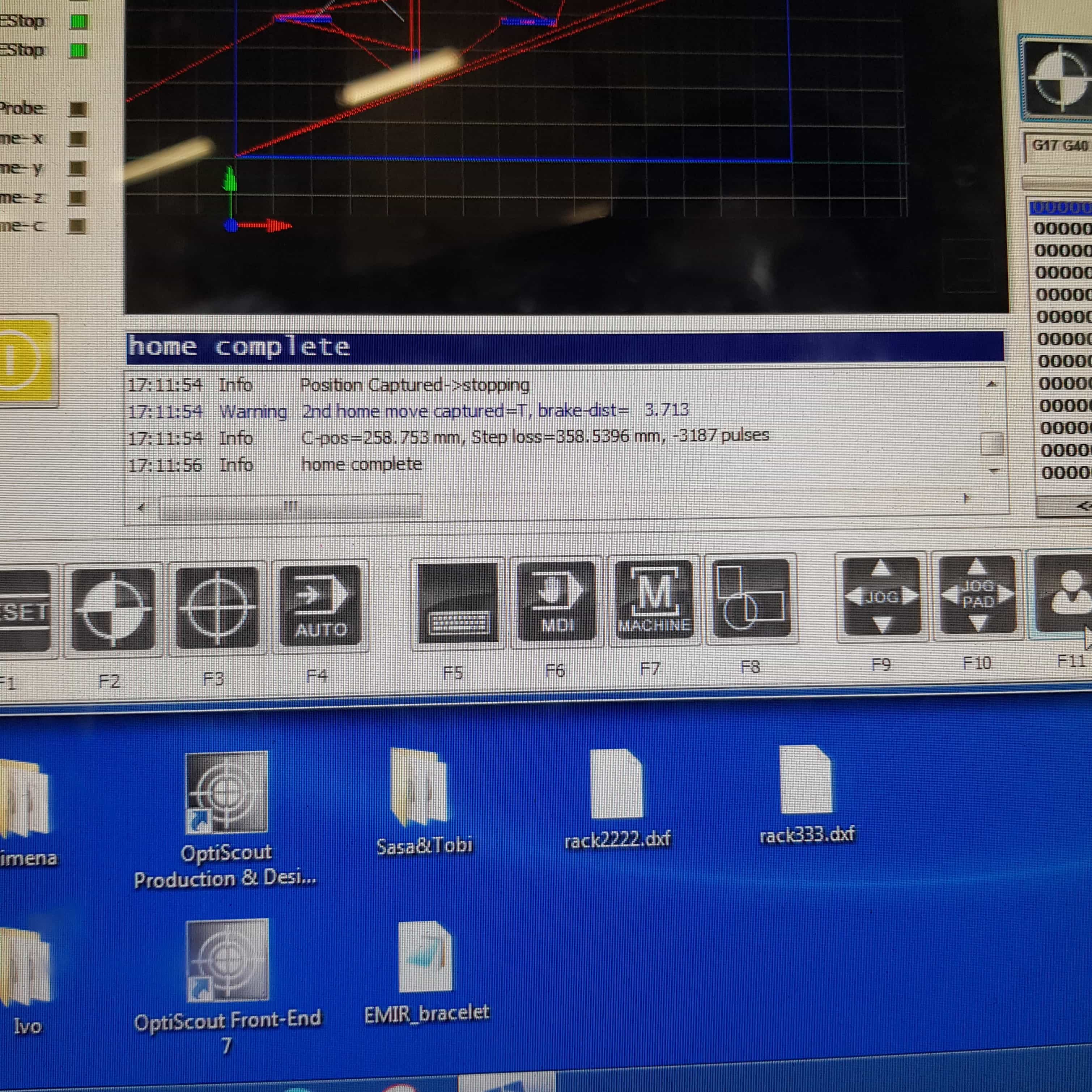
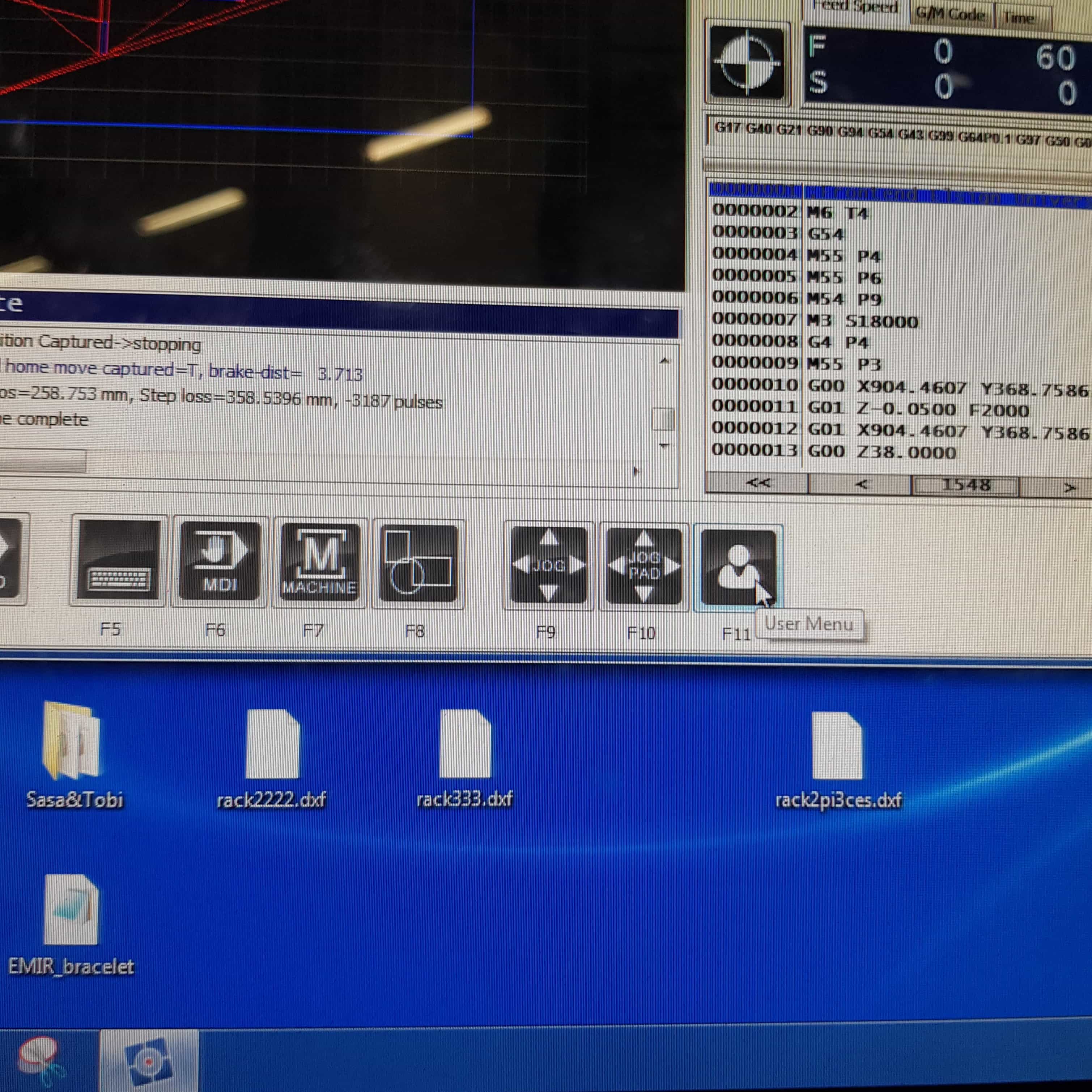
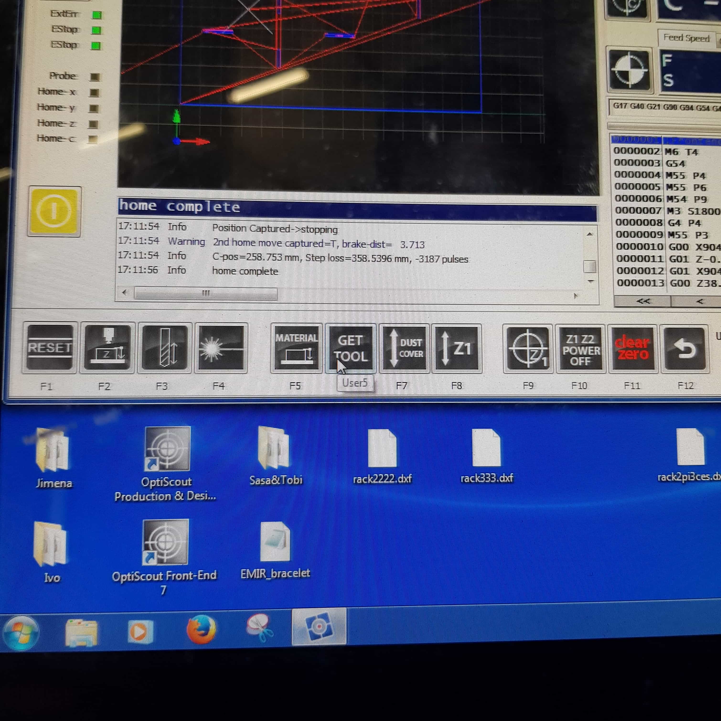
When completed the console will give a complete message
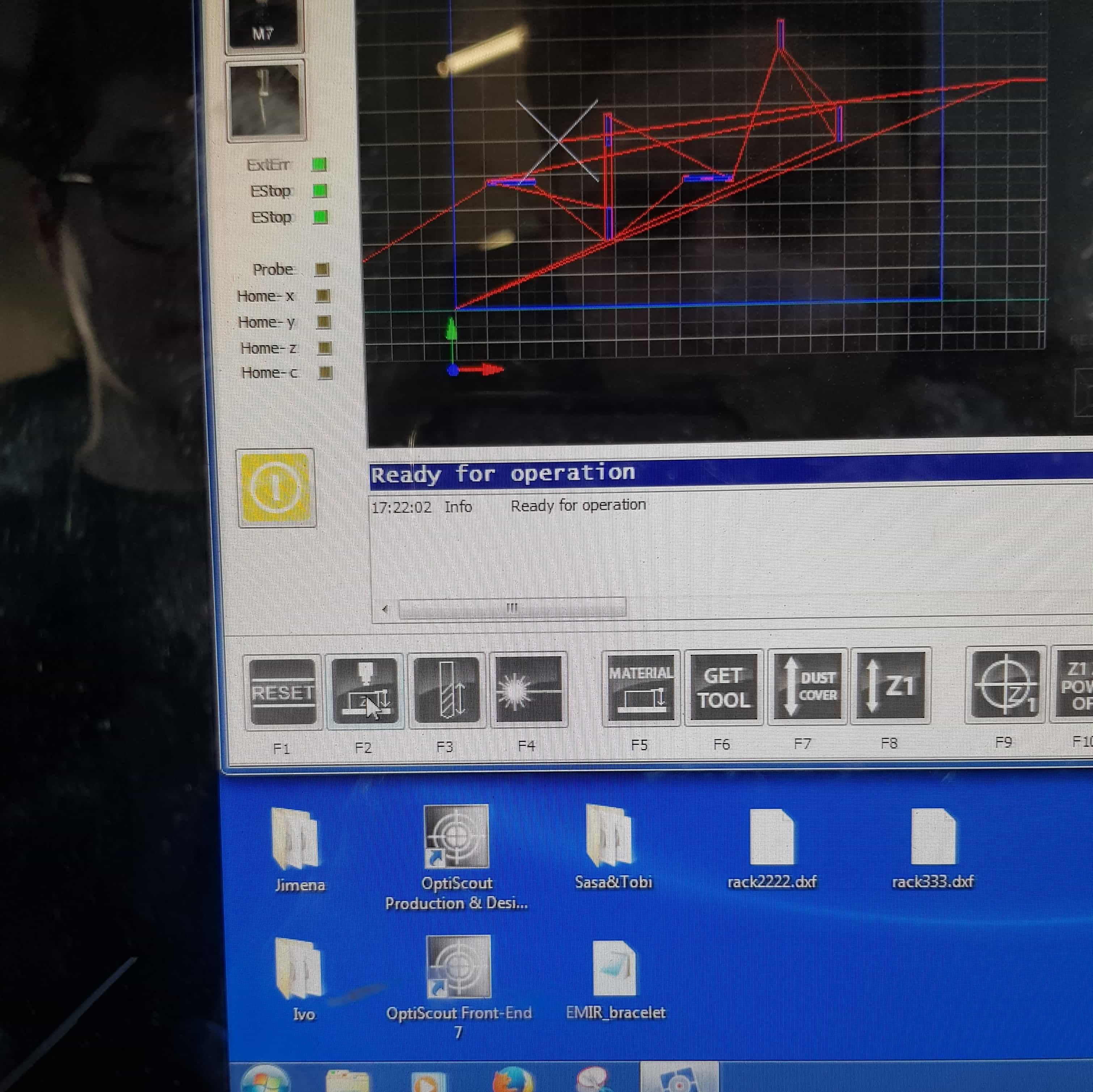
Now I had to change the milling tool, the tools are on the machine and giving the right commands is required to let the machine change the tool automatically. Just Navigate to F11 (User Menu)
and F6 (get tool).
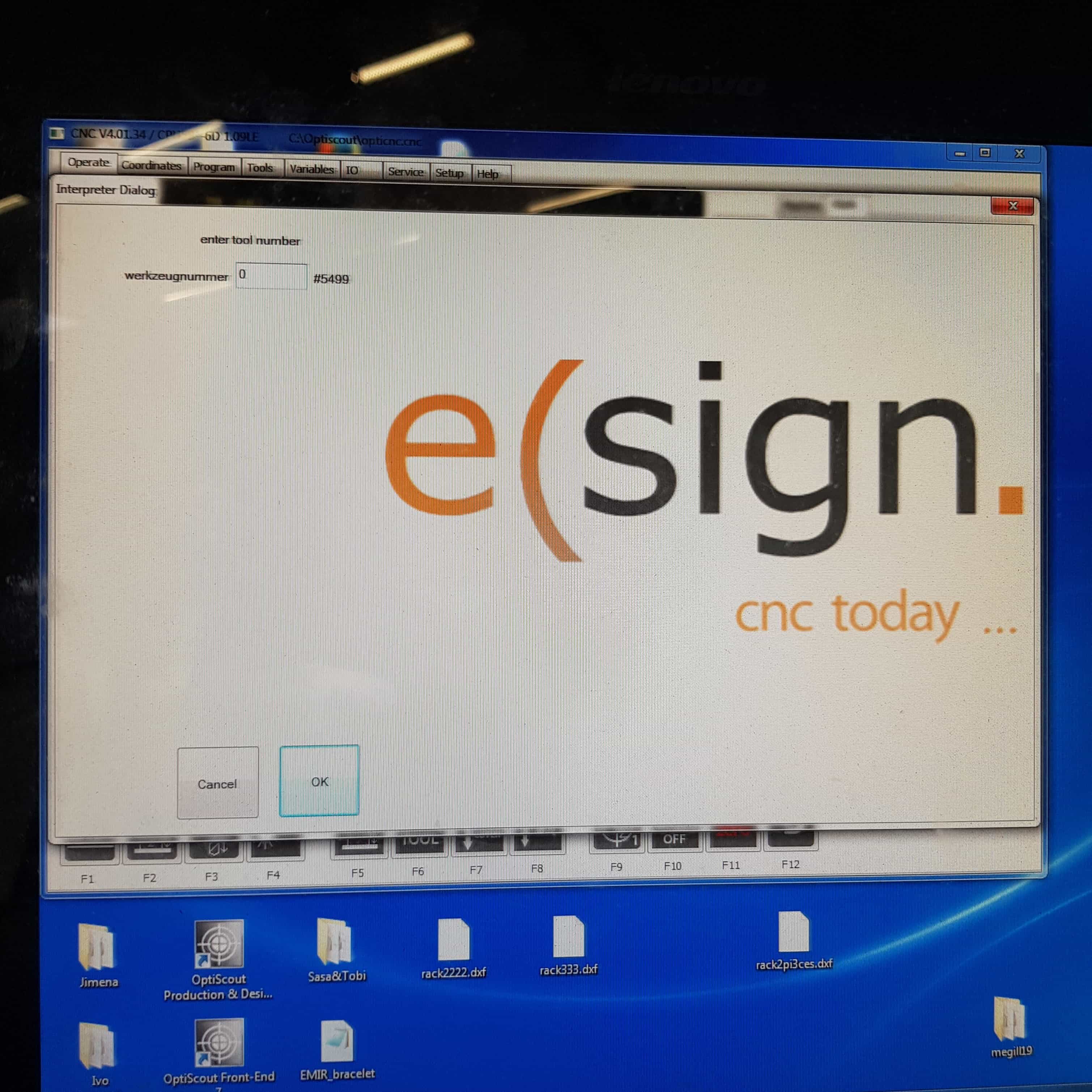
In the tool window I had to first select tool zero, this is the number for tool dropping.
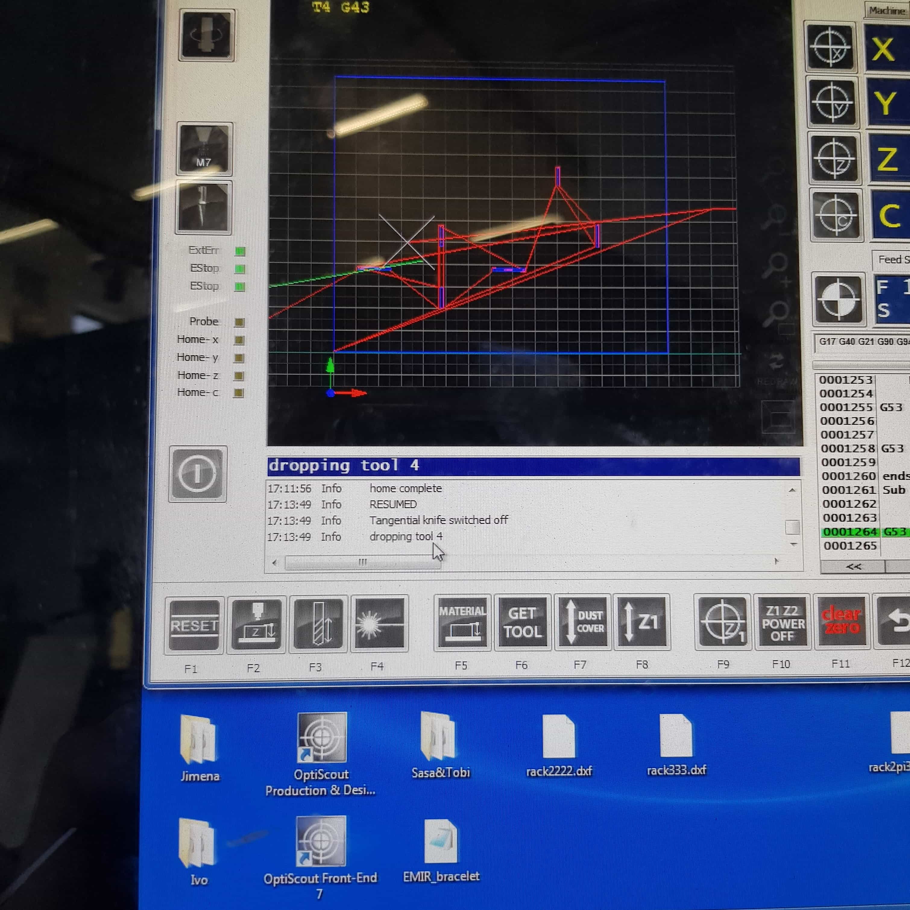
The machine drops the tool and show the process in the console
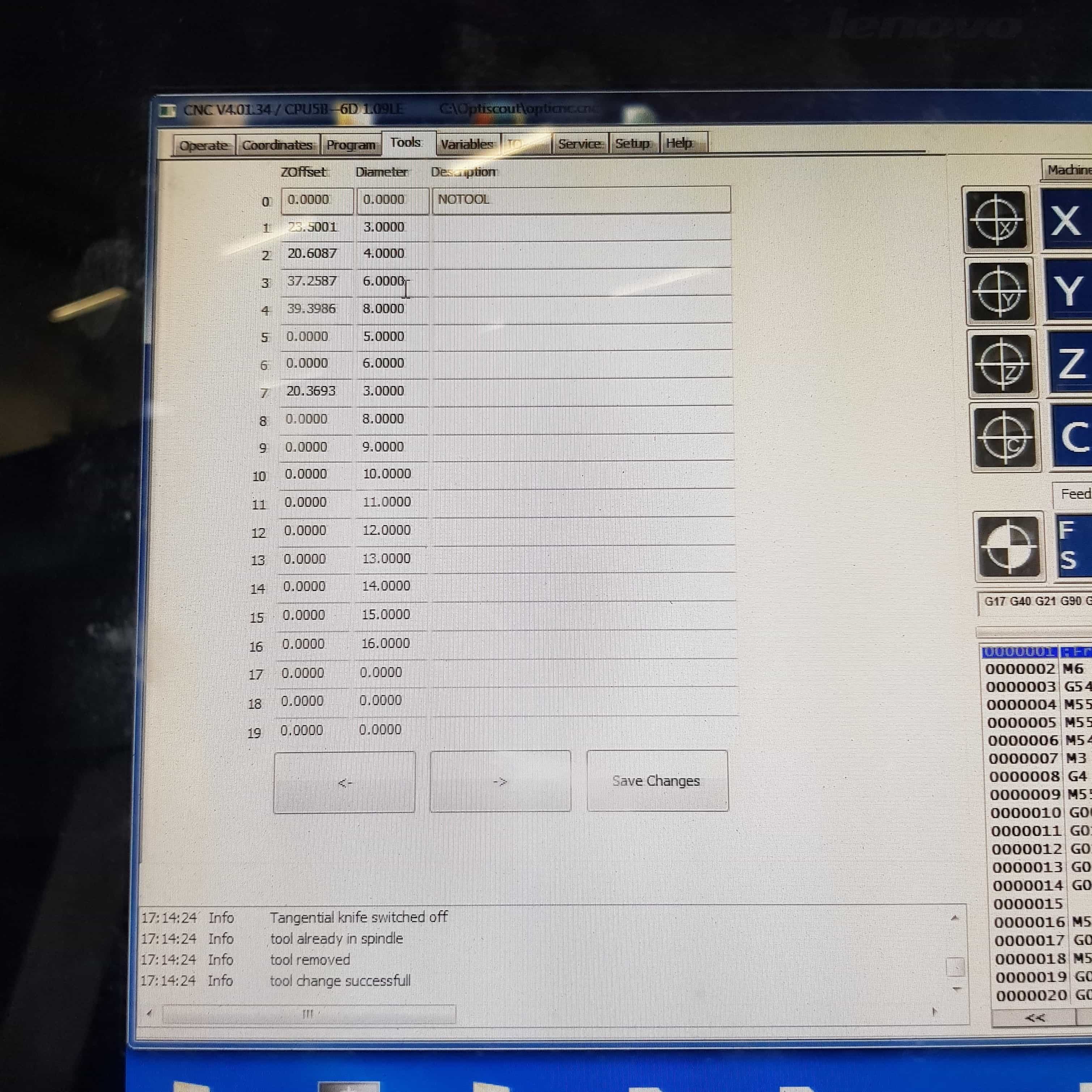
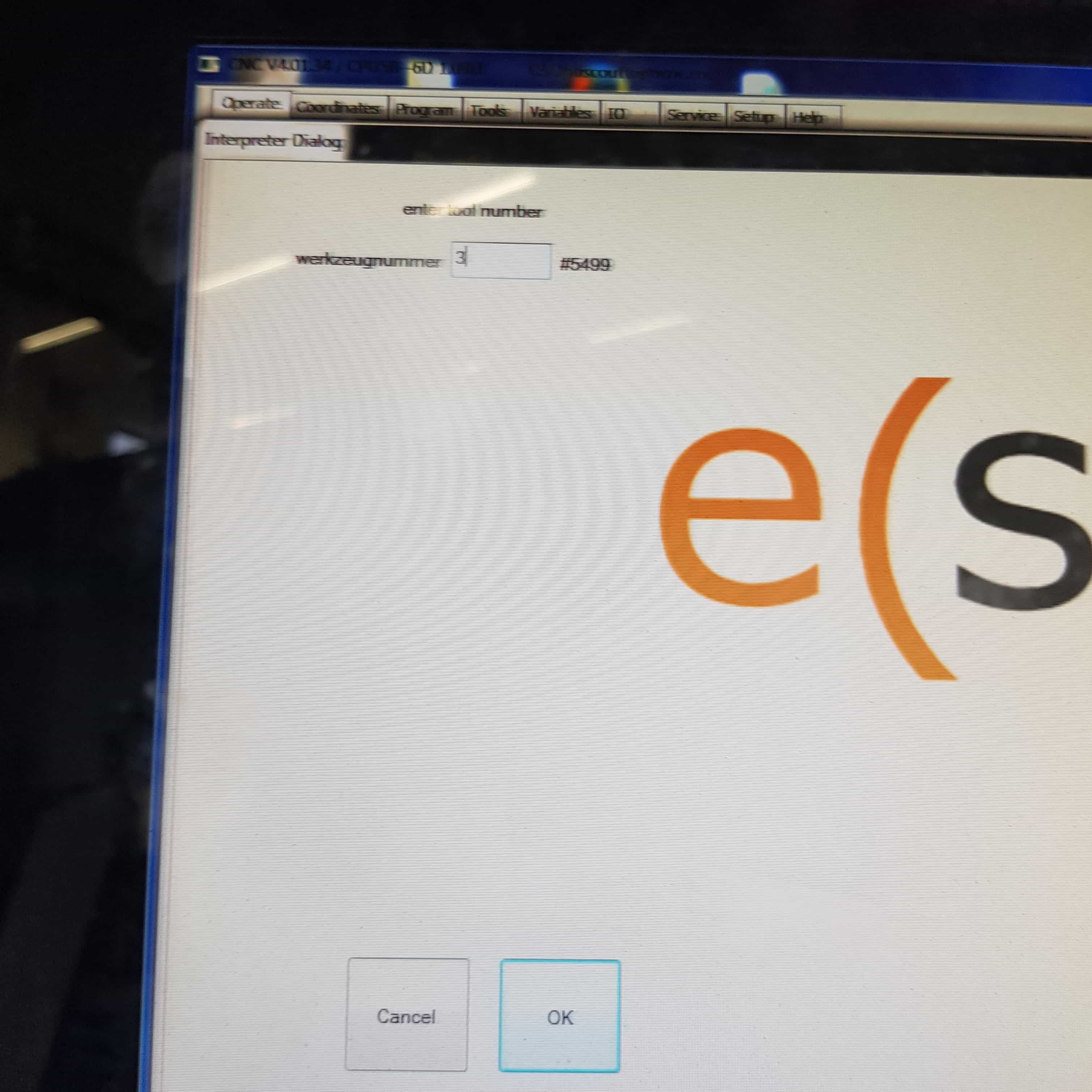
In the tools window we can check in which slot, which tool is and according to the diameter you need you can type it in the get tool window.
I will need the 6mm tool, which is in the third slot so I type in "3".
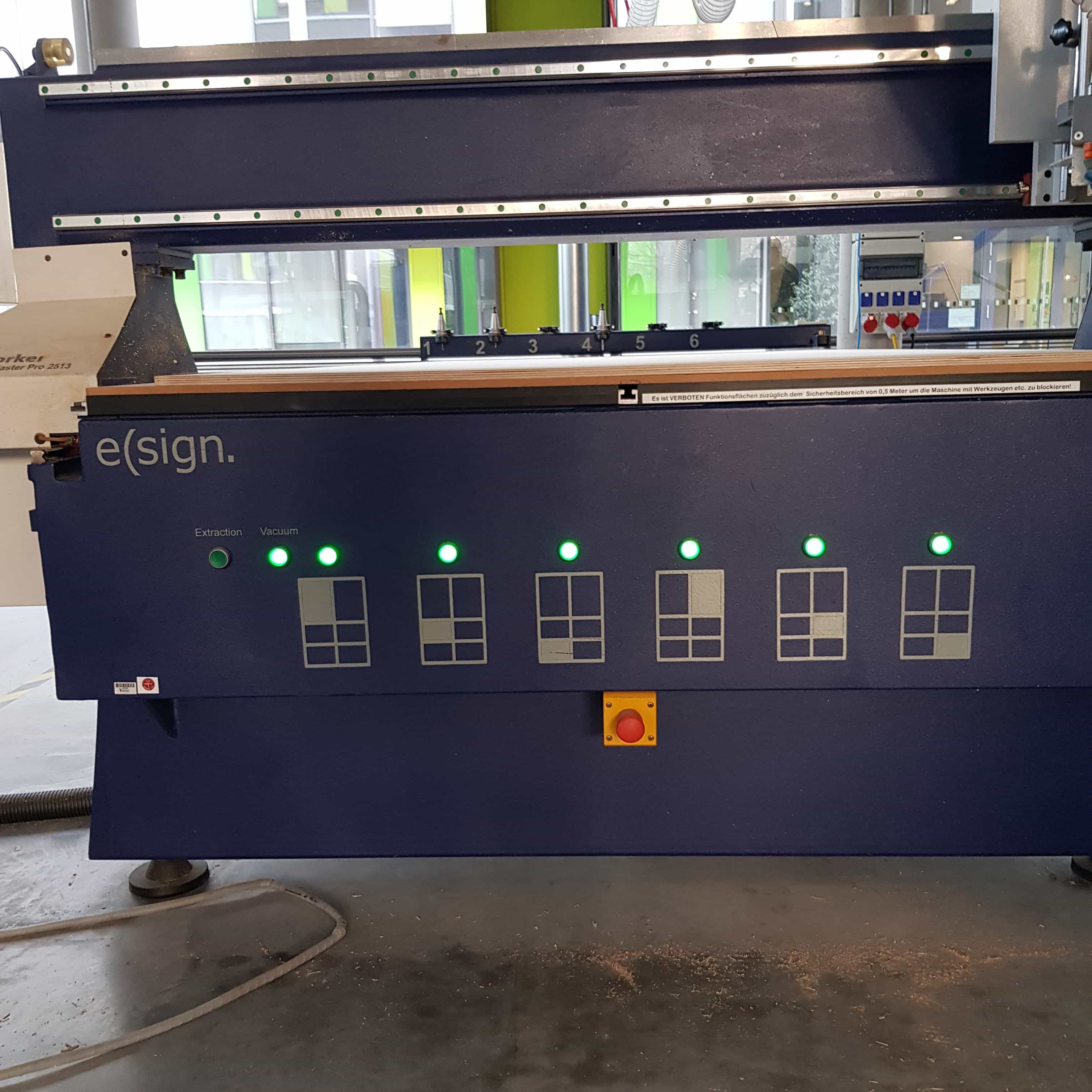
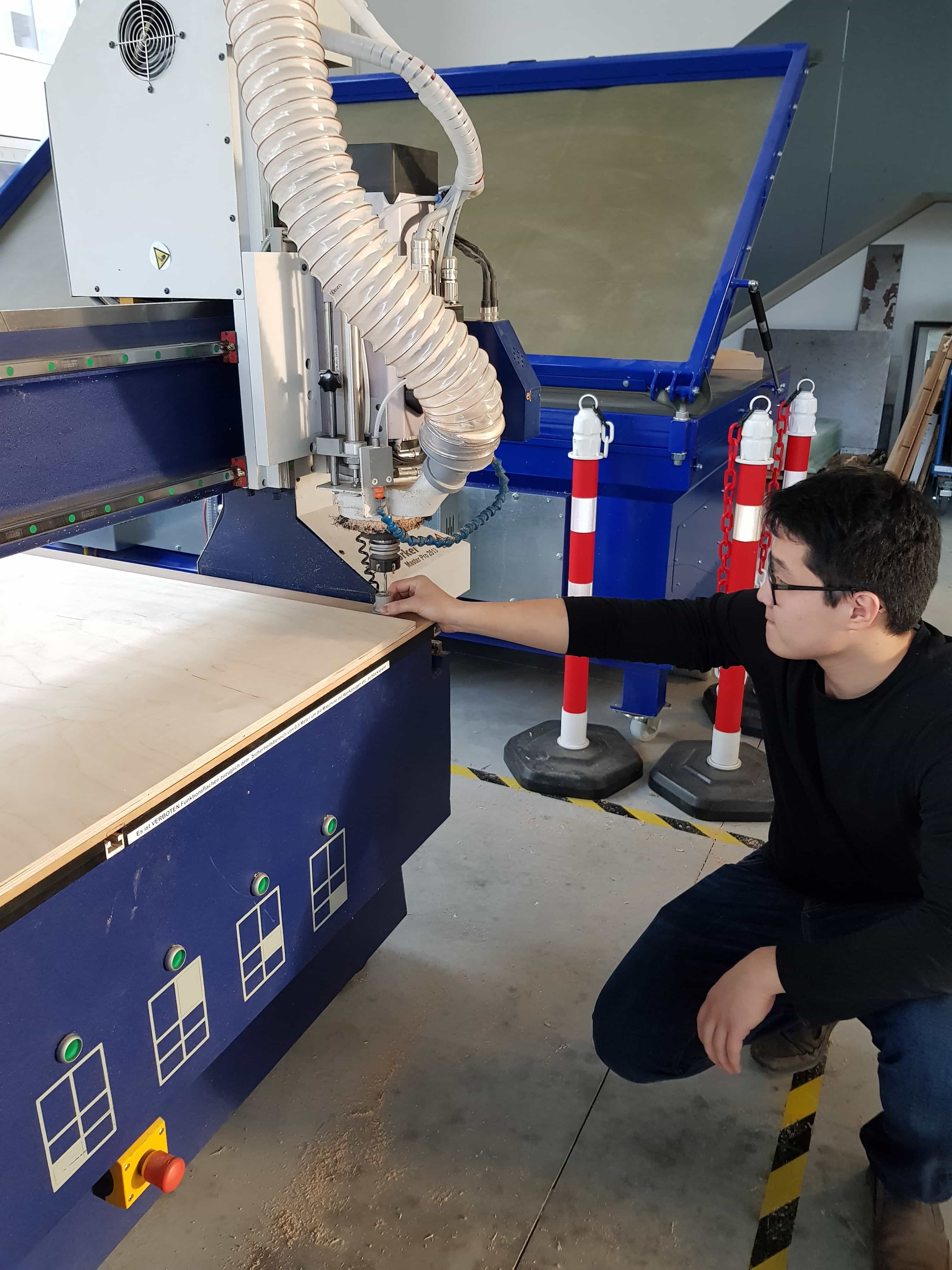
With the right tool I can start to set the home/start point, but never forget to turn on the vacuum on the machine so the plate can't move otherwise the homepoint could be destroyed when the plate moves.
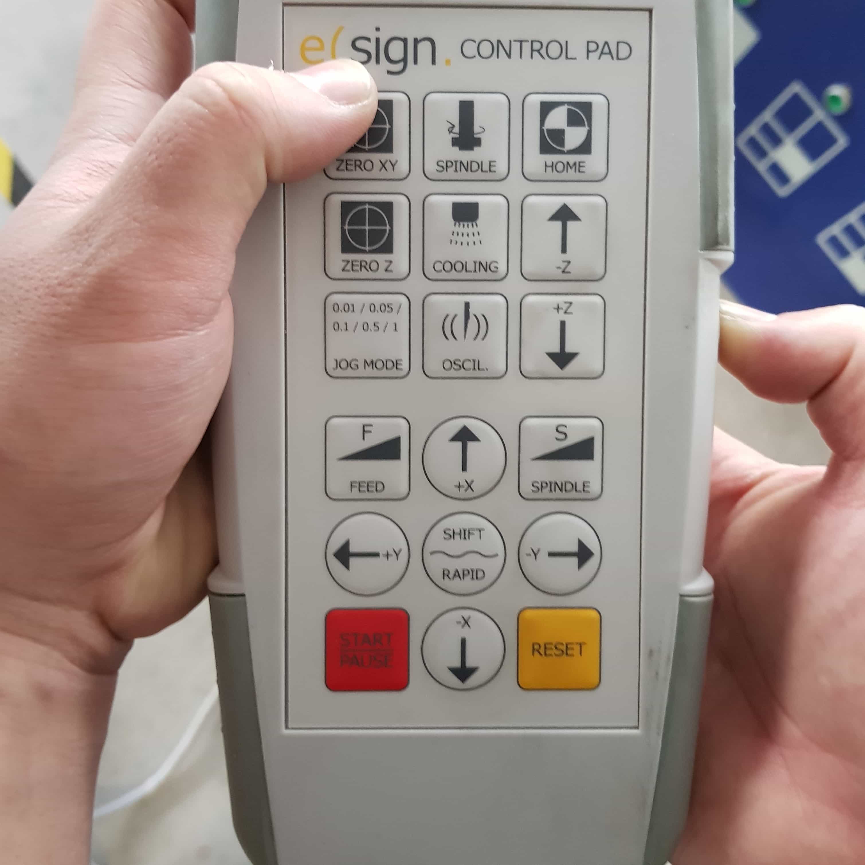
I now simply bring the head to the point I would like to start using the controller. On the side of the controller there is a safety button, to use any other button on hte controller you first have to hold down that button and simultaneously press the button to control the machine.
When the spot is right I had to press the "zero x y" button on the controller.
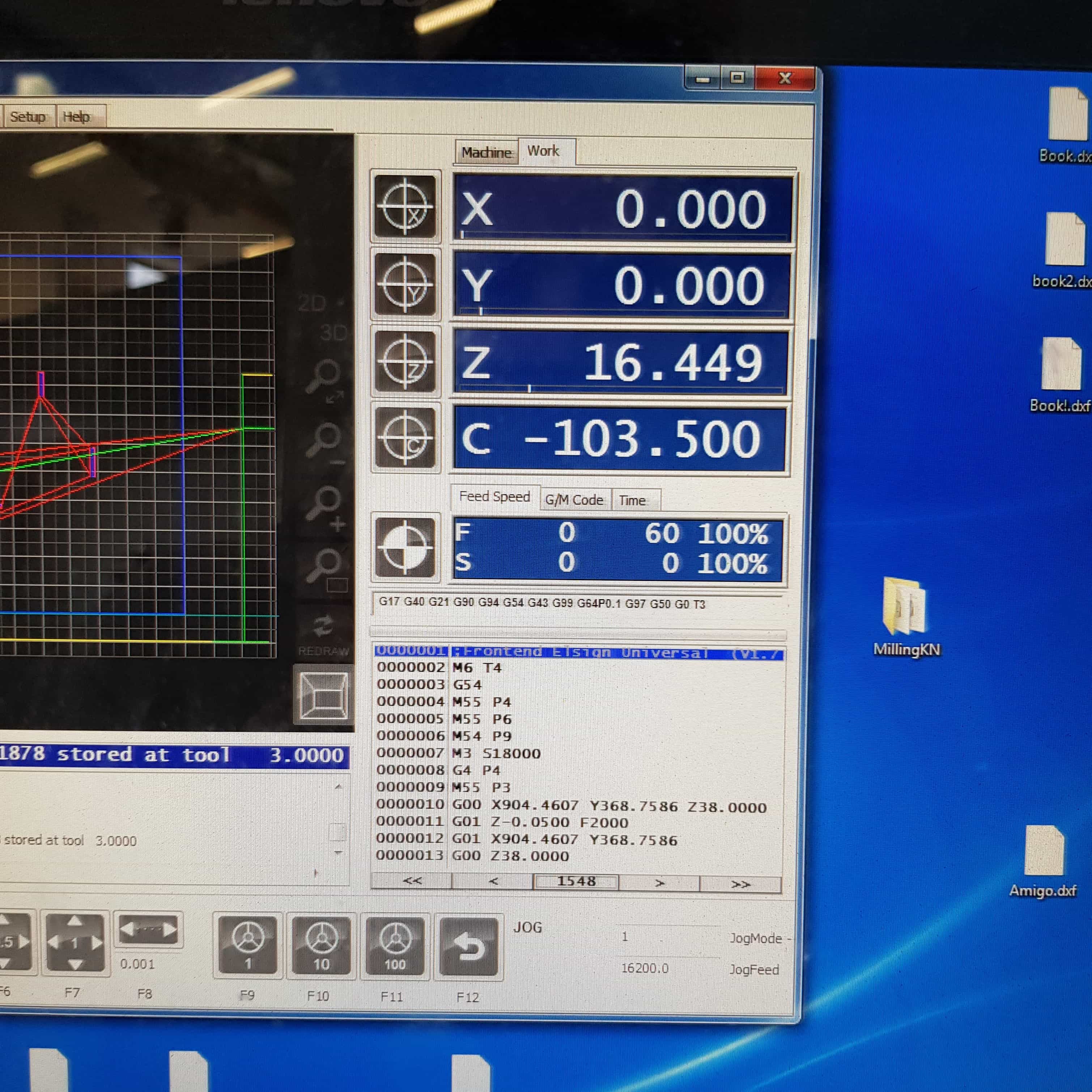
When the x and y axis is set, it should be zero on the computer too. If it isnt zero retry pressing the "zero xy" button.
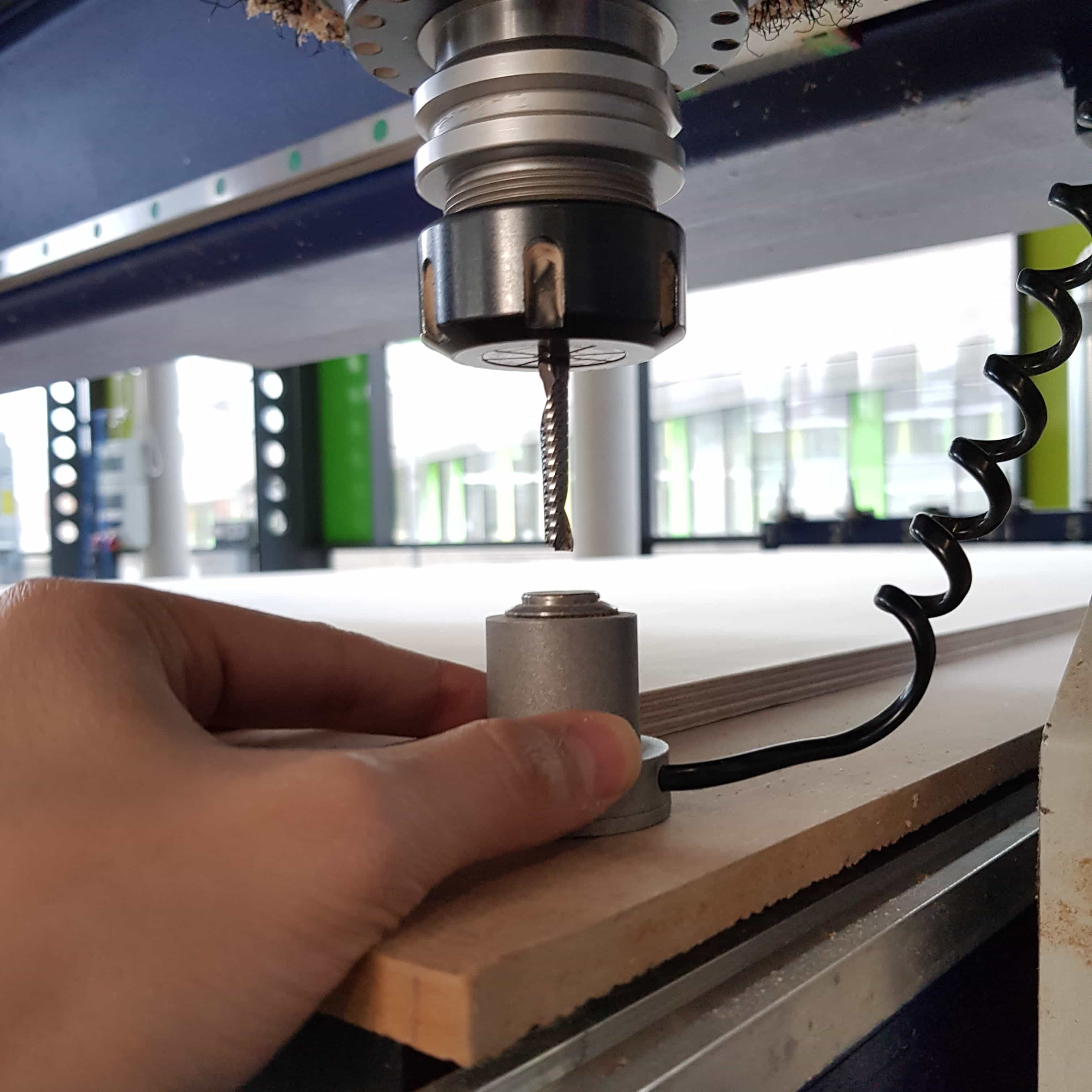
Then I had to set the Z axis, doing this is a two-man job so I got myself help. First I had to put the special calibration tool underneath the head.
Then I have to press option F2 (Set Z axis). The machine will start moving the head until the drill head touches the button.
As I said it is important that someone holds the tool in place
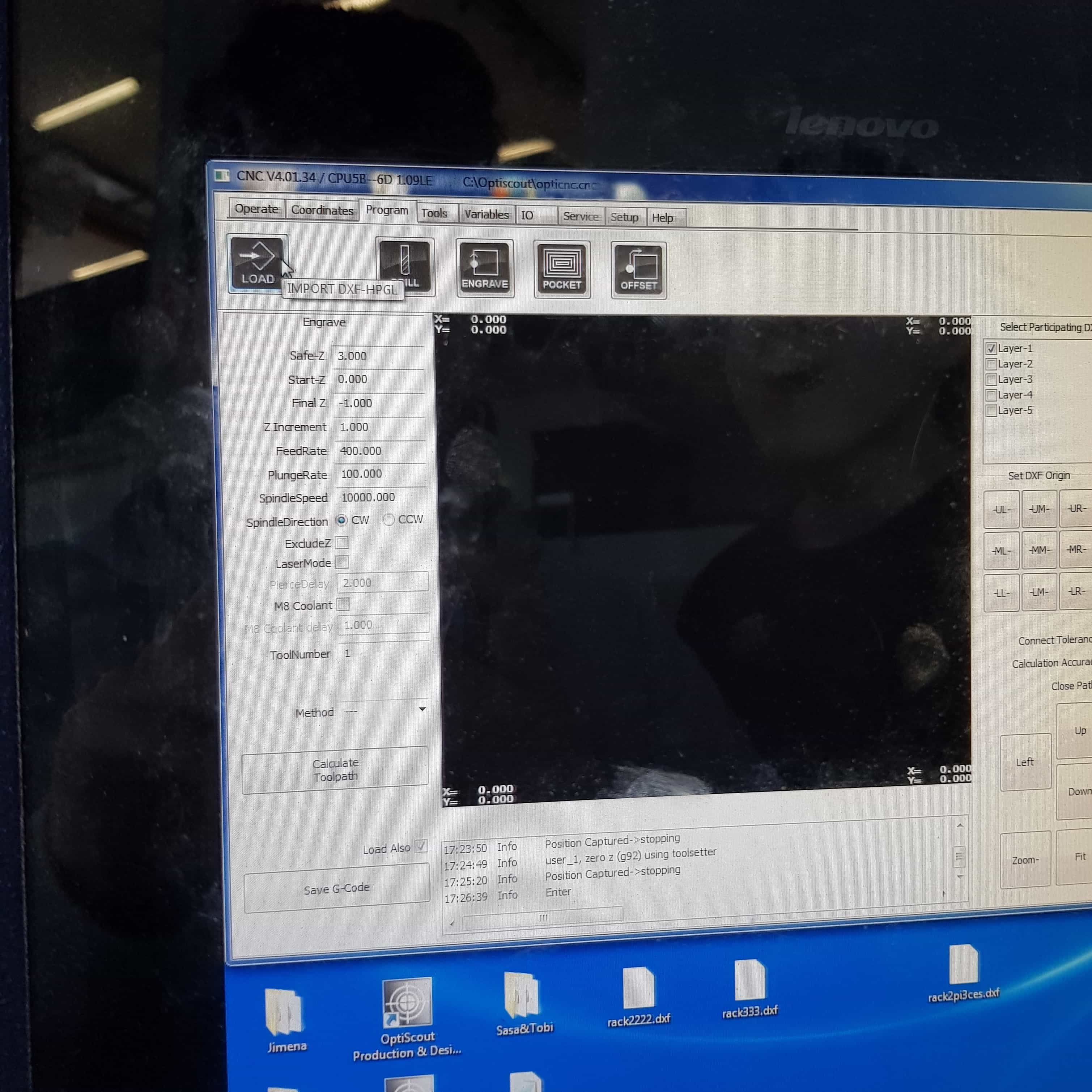
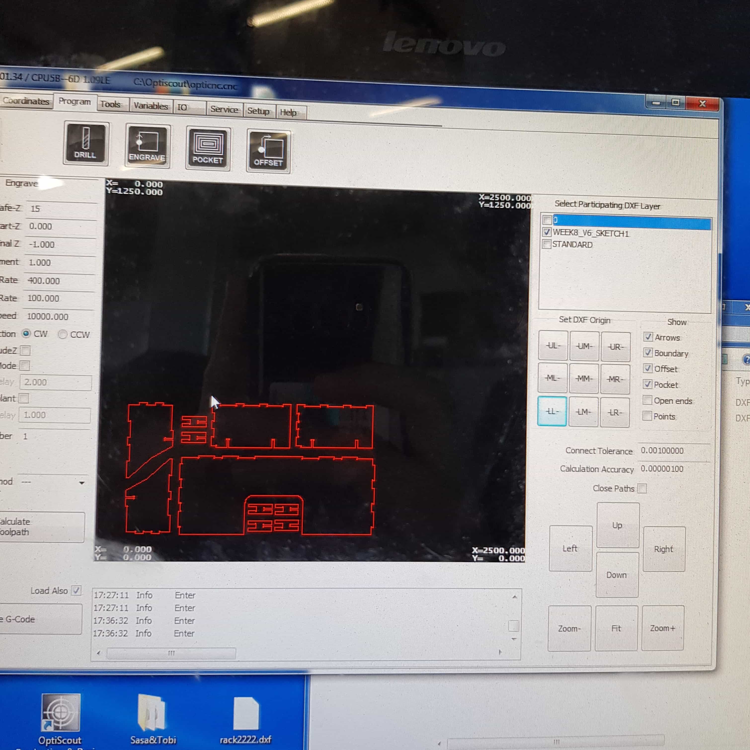
Now after every axis is set, we can load up our .dxf file into the software. I navigate to Program at the topbar and pressed the load button on the top.
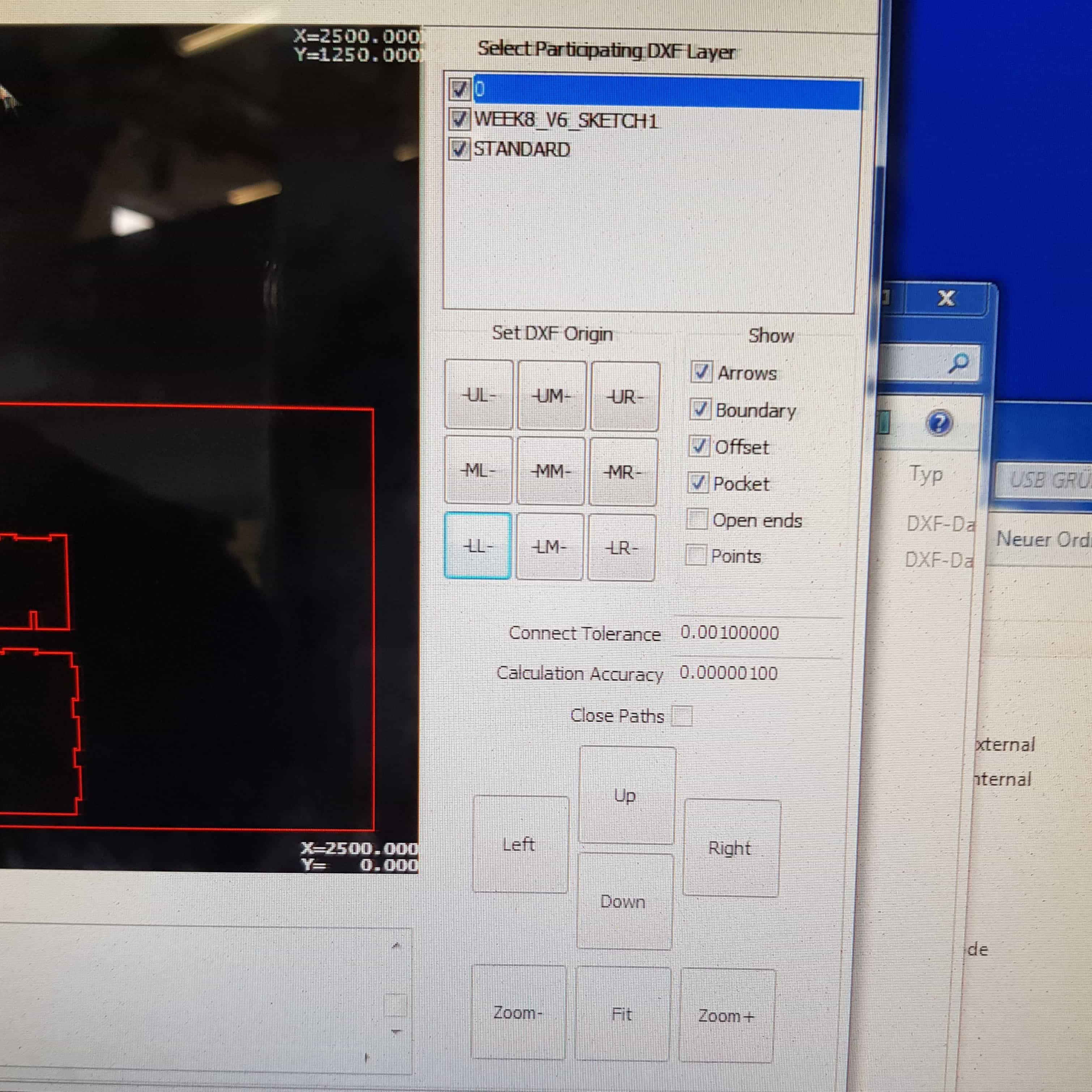
When my file is loaded and looks fine so far, I have to set the DXF Origin. In my case it was LL(Lower Left), but this can change according to your file. Just watch out that you press the "LL" button once because otherwise the software could get problems.
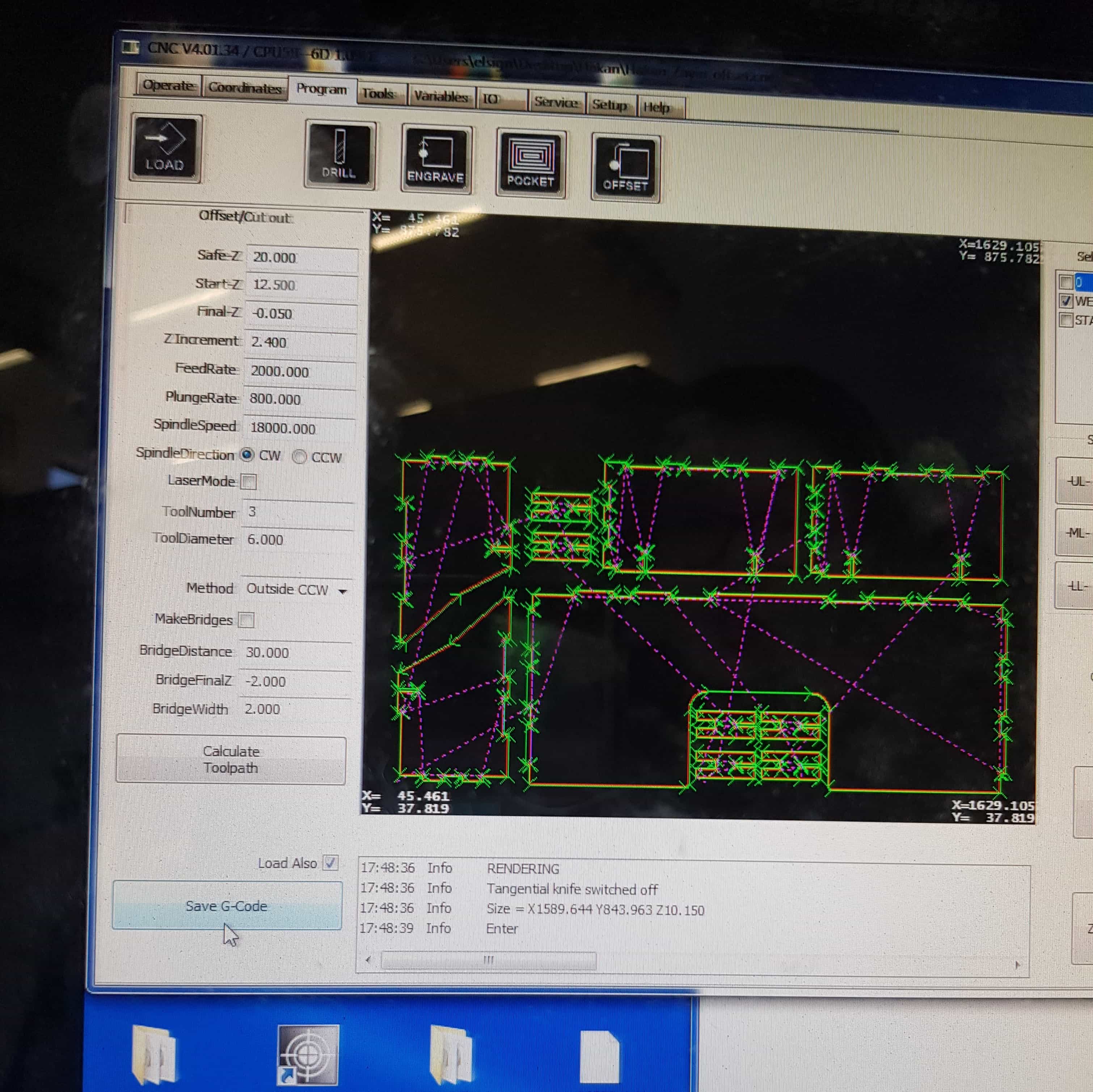
I had to do some offset/Cut out settings for my job:
Safe-Z = jump height of the head during the process.
Start-Z = starting point of the z-axis, mostly the material thickness + 0,5mm offset.
Final-Z = the deepest point the z-axis should go, usually 0 + 0,05 offset.
FeedRate = movingspeed of the drillhead in x and y axis.
PlungeRate = movingspeed of the drillhead in z axis.
SpindleSpeed = RPM of the drillhead.
SpindleDirection = Clockwise and counterclockwise.
Toolnumber = the number our tool has to be, in my case tool 3
ToolDiameter = the diameter of the tool used.
the only thing left is hiding the other layer except of the cutting layer. In my case the cutting layer was named after the fusion360 filename.
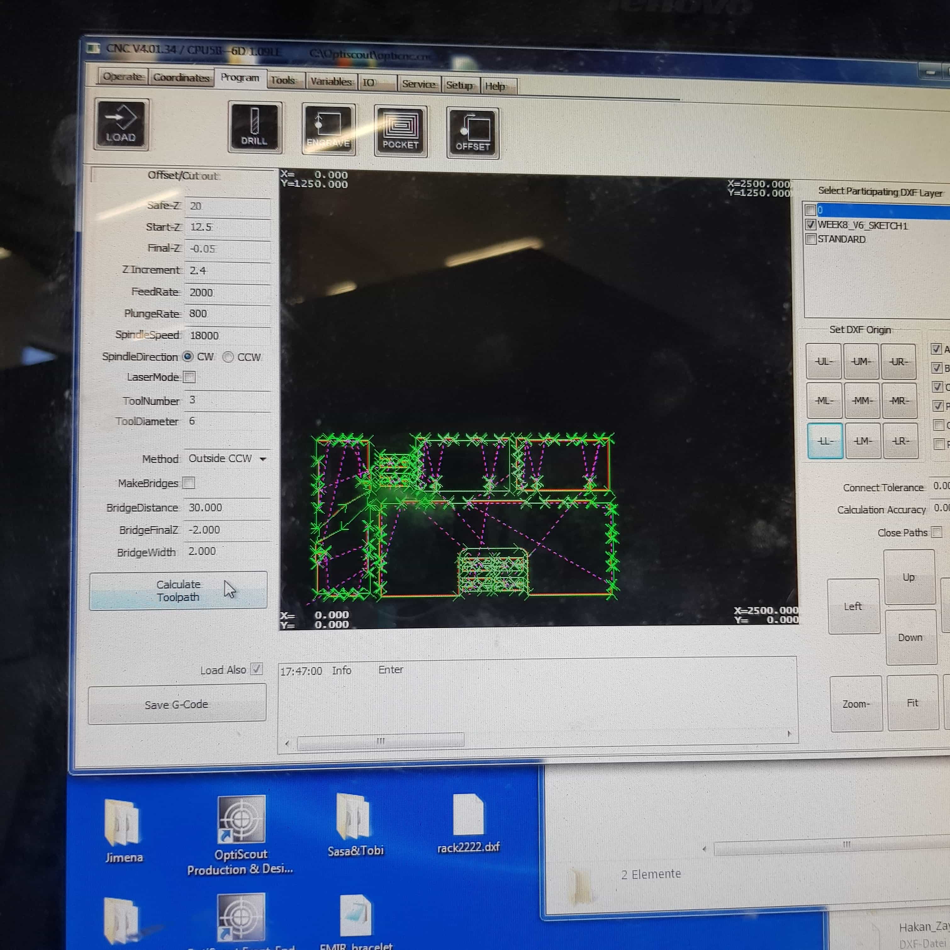
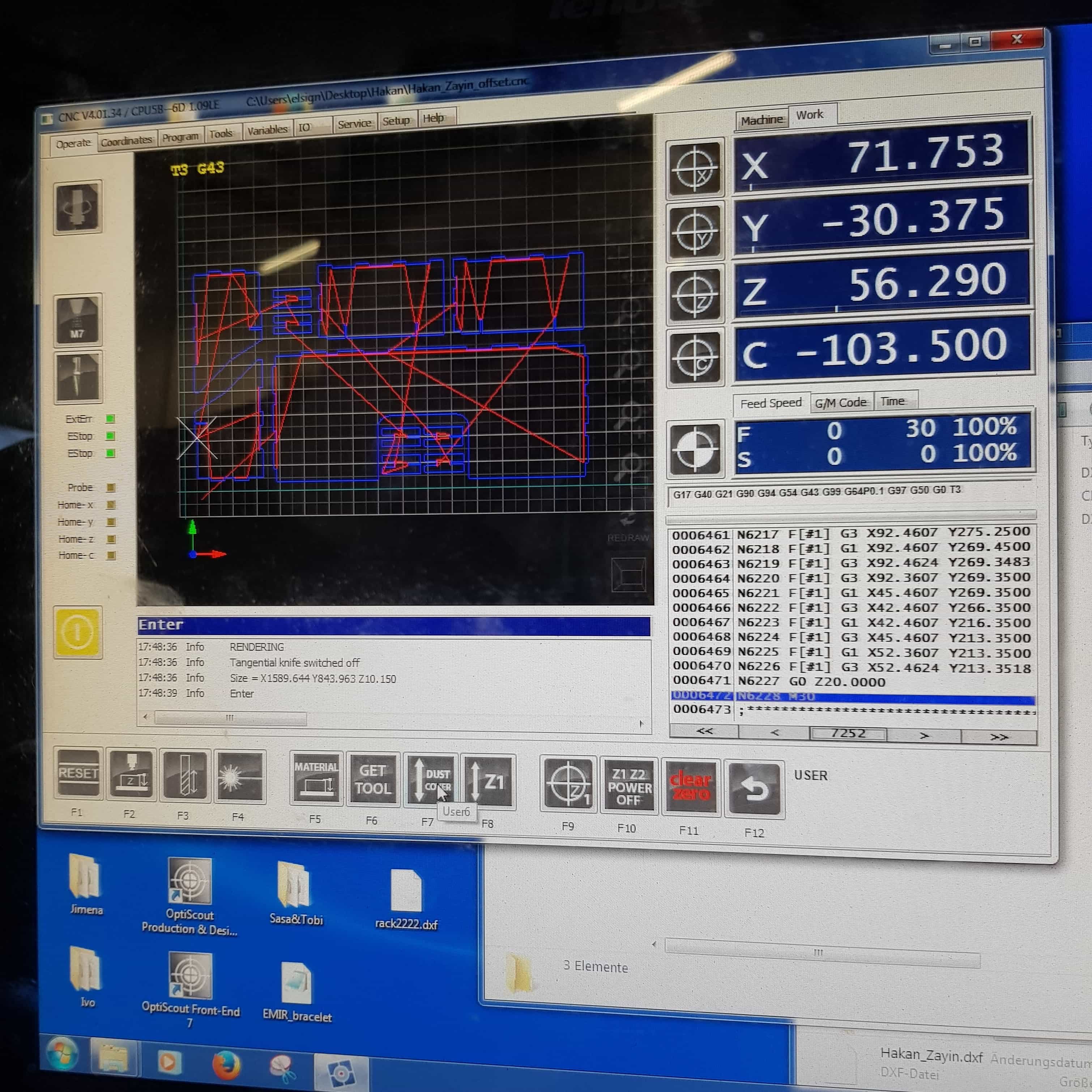
Now I was ready to calculate the g-code, by pressing on the "Calculate Toolpath" button.
the window shows which way the mill will go, so it is recommended to check if everything looks right. Everything looked fine so well so I was ready to save the g-code pressing on the "Save G-code" button
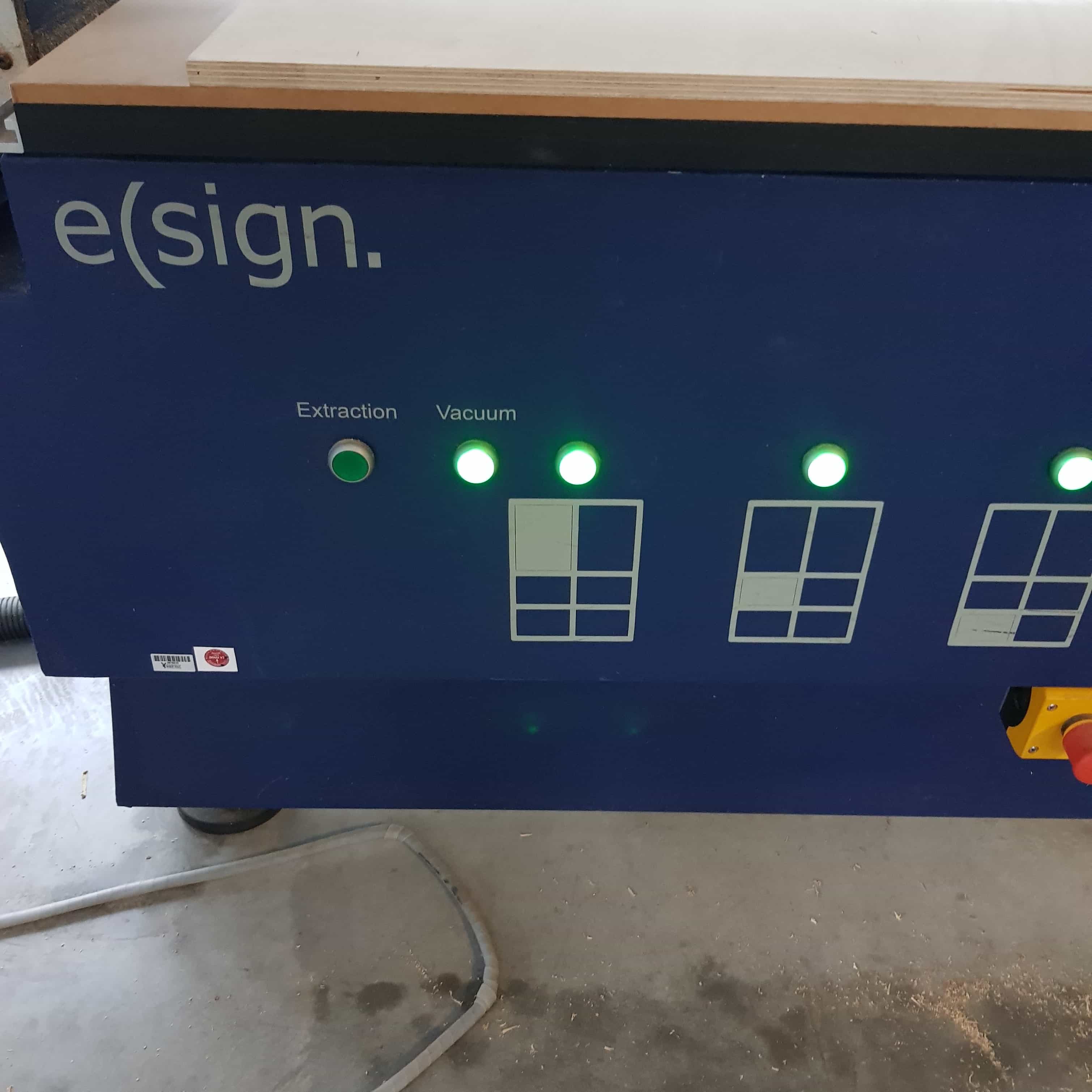
Before I could start milling I had to make sure that everything is prepared. The cnc-machine only works fine when the follwing things are on.
Please make sure that the follwing parts are working fine and never turn them off during the cutting process
1. CNC-Vacuum: Holds the material at its place so it can't move during the process
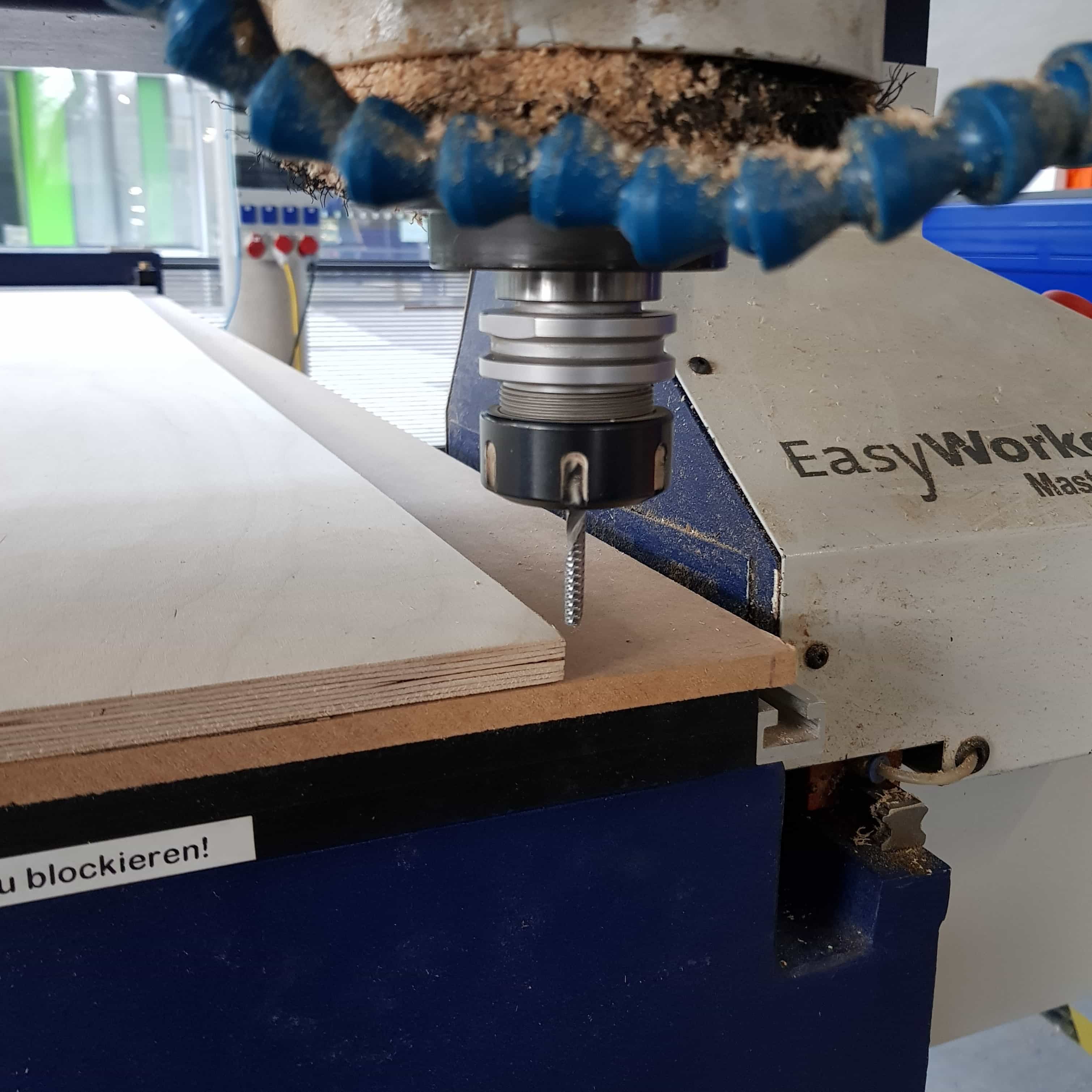
2. Big compressor: A bigger machine connected to the drill head that vacuums the off coming parts of wood.
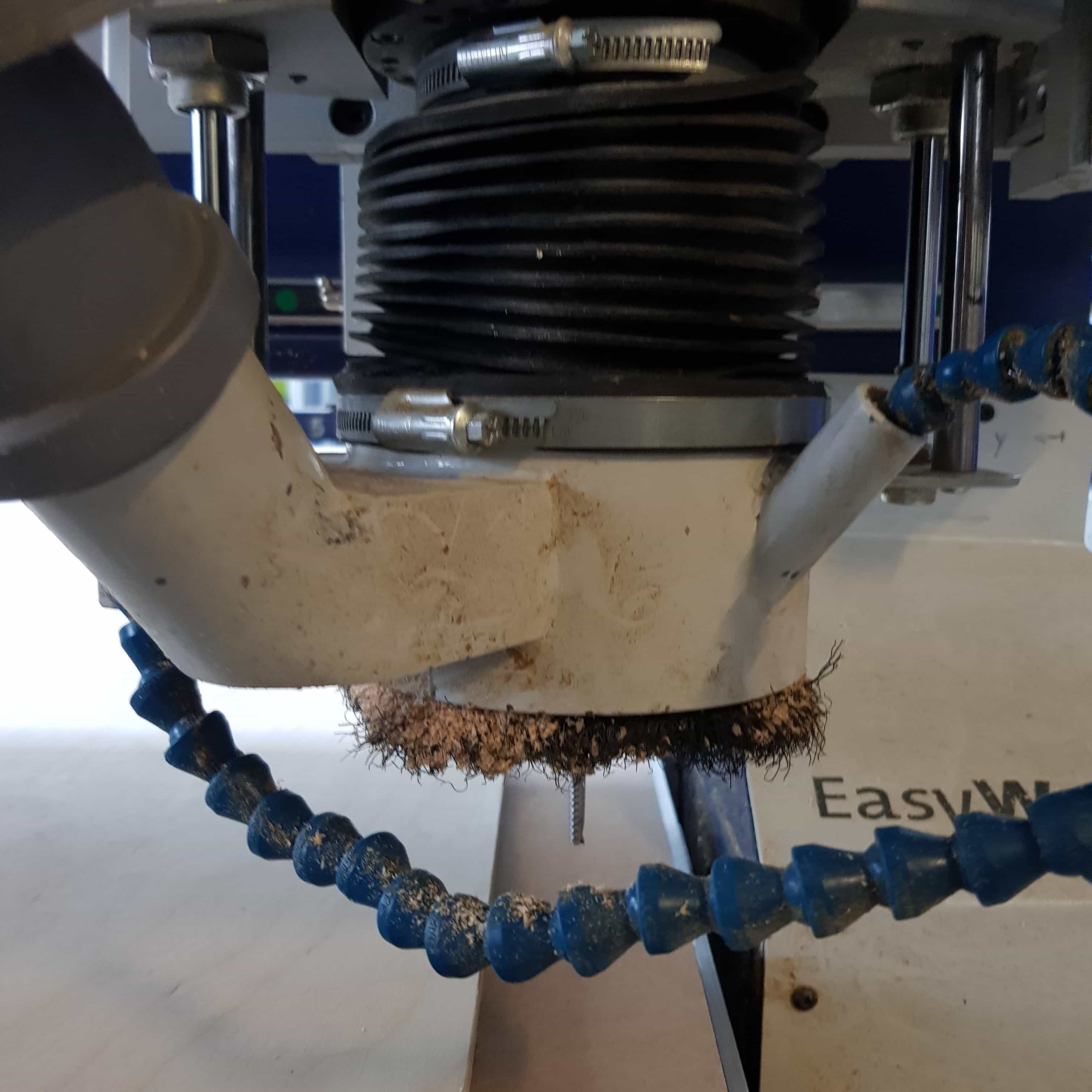
3. Dust Cover: Dustcover on the drill head of the machine move it down by pressing F7 (Dust Cover) in the homescreen
The dustcover should look like this
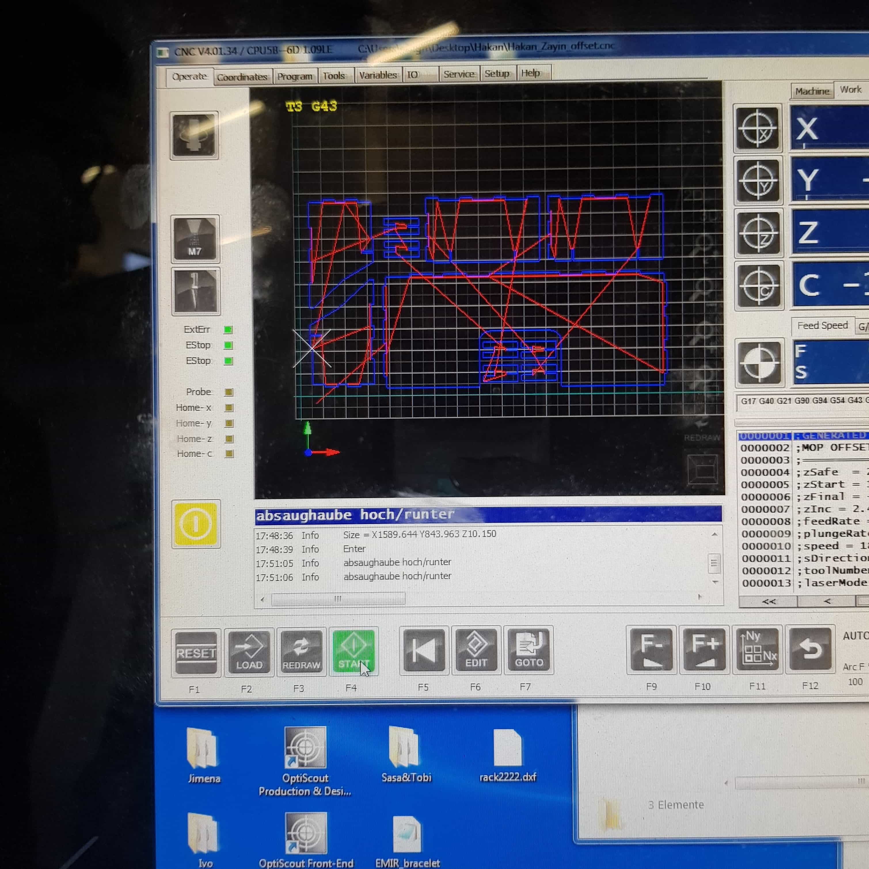
When everything is turned on and works properly we can start the process by pressing the start button F4.
The machine works his way through the material, but attention no machine is perfect stay in front of it as long as the job continues to be sure everything goes fine. Safety iis the number one priority when using such big machines. Sometimes the machines will have problems, in my case there wasn't any problems and anything worked very well, but the machine could cause dangerous situations. Using the cnc machine is not very complicated and using it for the first time was very fun, although I was not very experienced it was a good example in how to produce bigger things.
YOUTUBE LINK
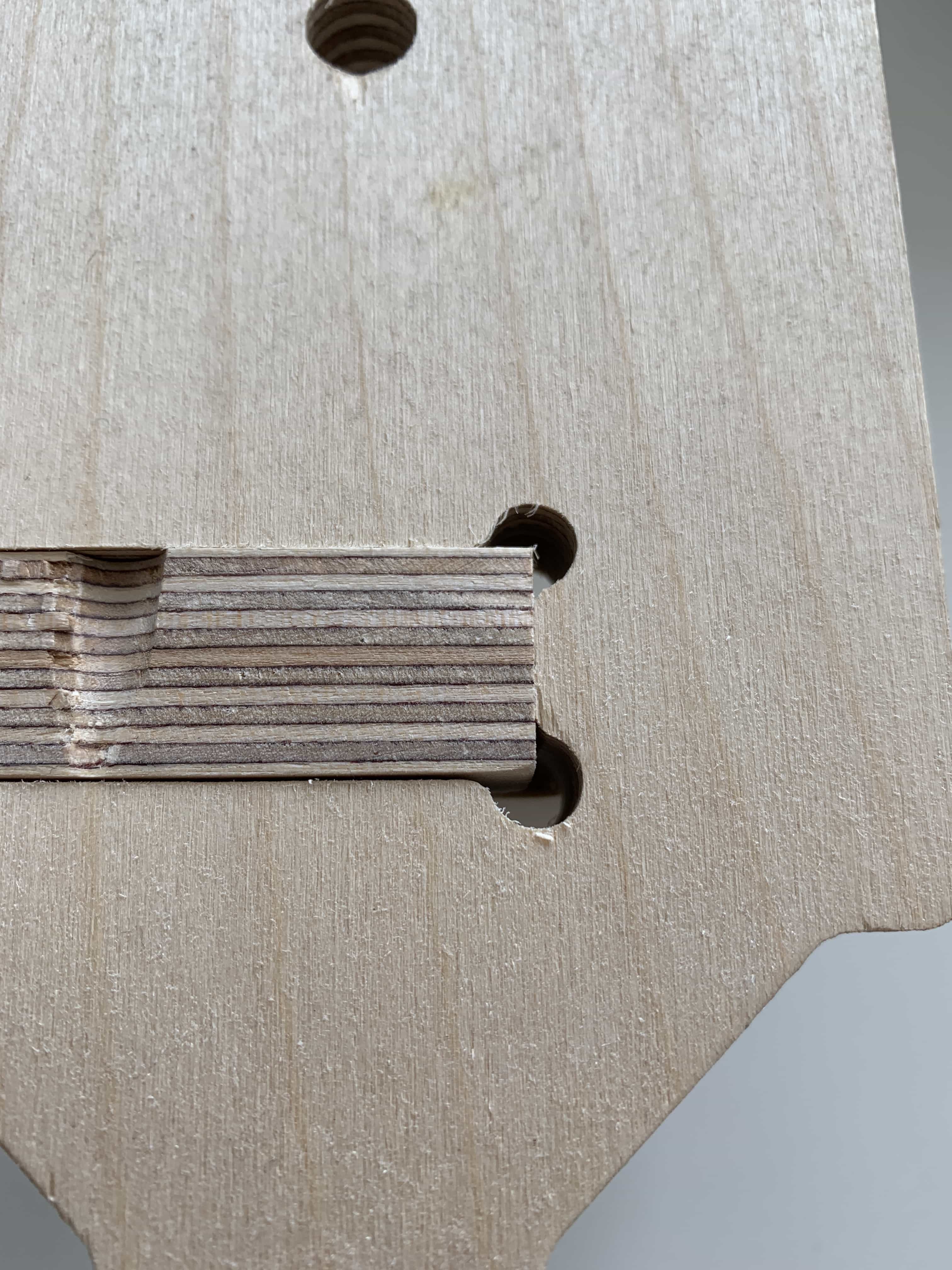
The final part was to assemble my desk and try it out.