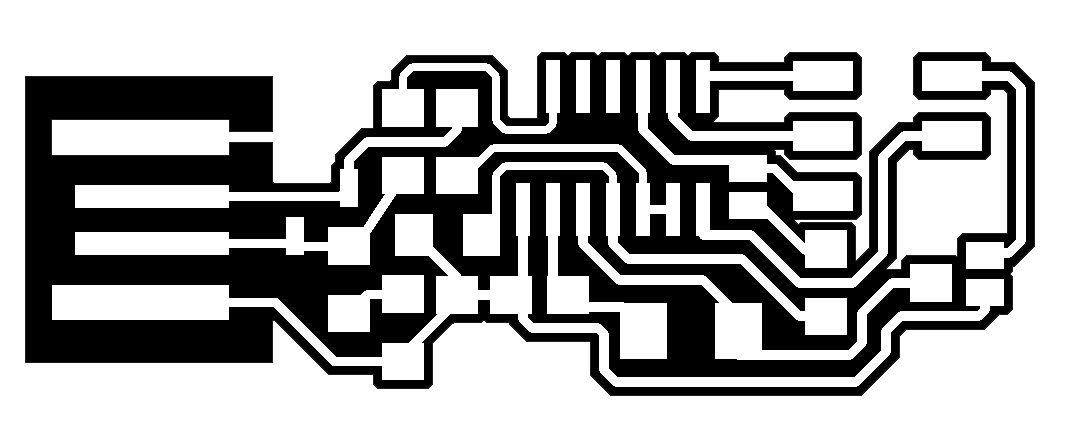
This week I had to do a in-circuit programmer by milling the PCB and program it. To do this I had to create a gcode for using the mill first. To do this I had to have a png of an circuit board, in my example I have used the FabISPkey from Andy Bardagjy Andy's documentation
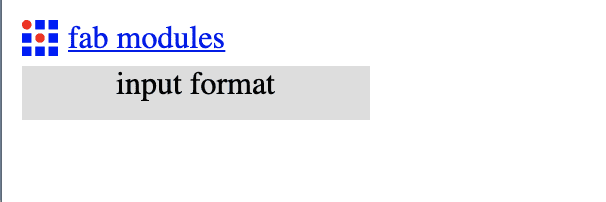
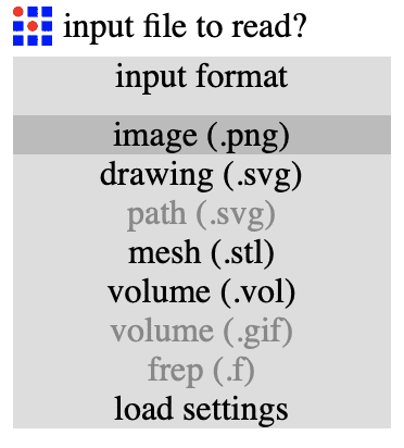
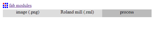
For creating the gcode, I have used the Website "fabmodules.org". First I had to select which kind of image I wanted to import to the website.
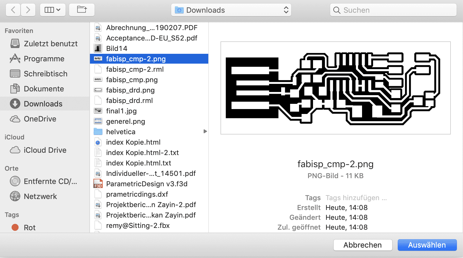
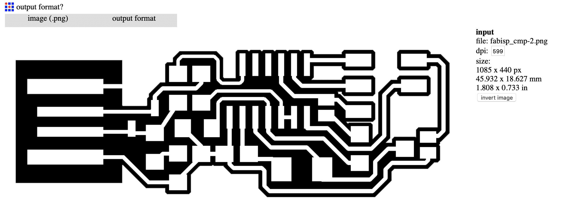
Now I just selected my png which I got from the FabISPKey documentation
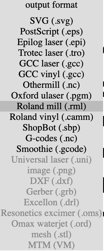
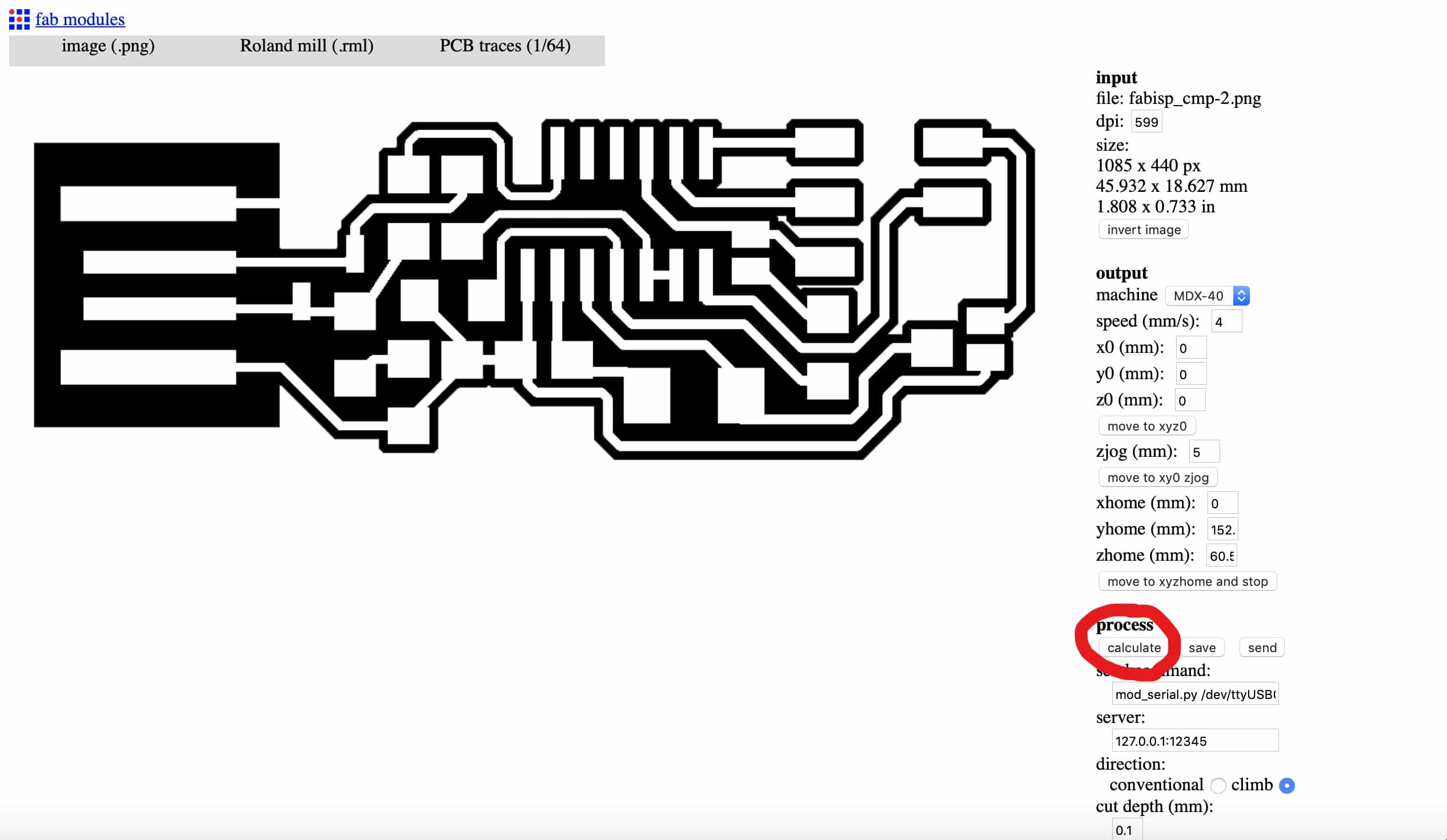
After the import is completed the website shows the imported image, now I pressed the "output format" button, to select the right output format.
In my case I had to select the roland mill, because I will use a roland mill to mill the board.
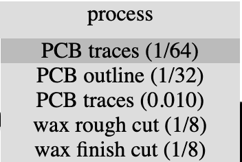
Then I had to select the process, which in my case are PCB traces (1/64).
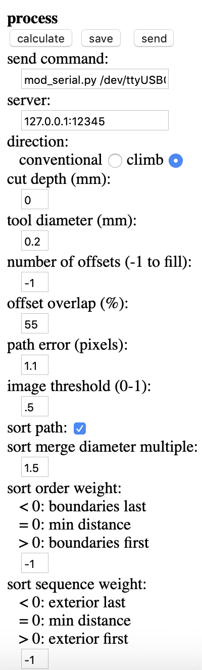
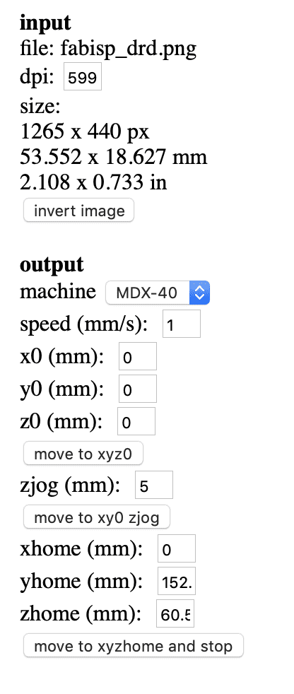
After these steps a menu pops up on the right side. In this meu I can type in different preferences for the milling process. The preferences I have set are first of all the machine I have used, the MDX-40. Other important settings are the speed, which I have set to 4 for milling and the zjog.
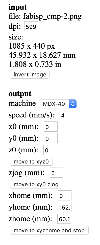
Also I had to set the the cut depth, in my case 0 because I will set the mill exactly onto the milling board, the number of offsets to -1 to get the fill and the offset overlap to 55%. These settings will work for a FabISPkey, other boards could need other settings!
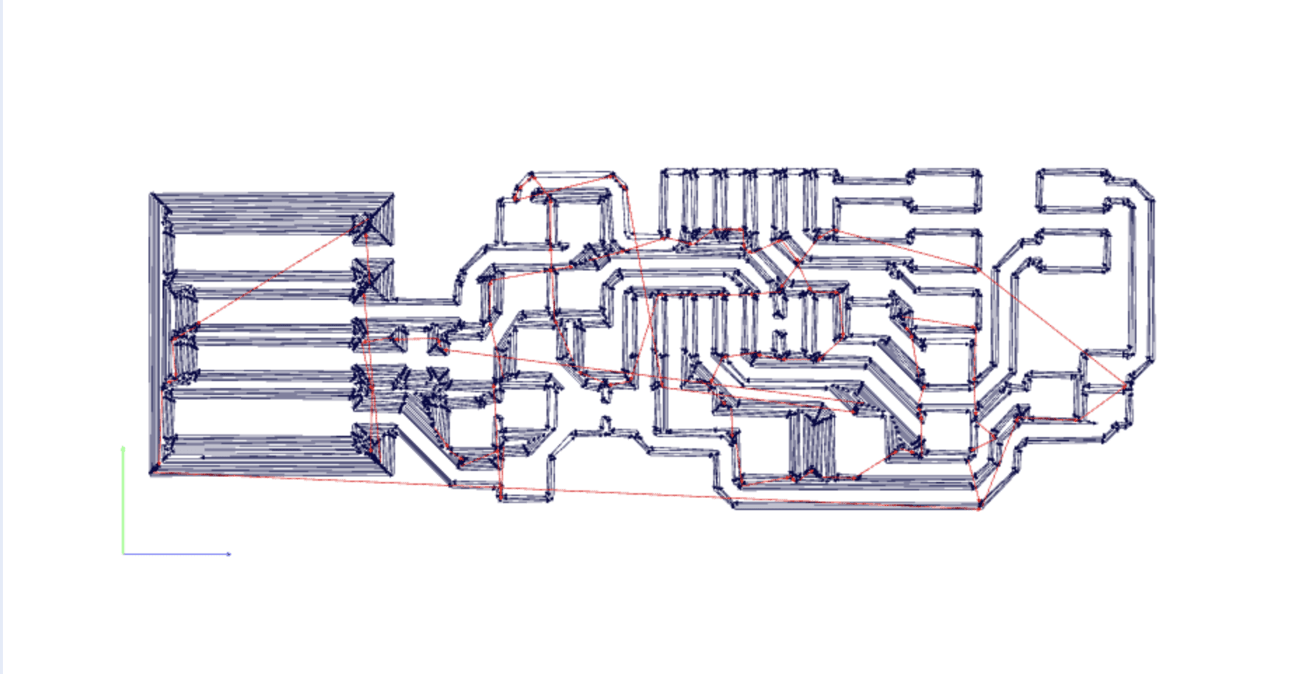
Now after setting everything up, I can calculate the gcode for the mill pressing the calculate button.
The result looks like this:
I had to repeat these steps for the gcode to cutting out the pcb. Doing this is a little bit different. First you have to get the same image but instead of a circuit there is just a frame.

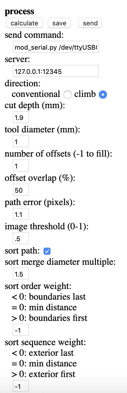
In the preferences I just have to change the speed to 1, the depth to the height of the milling board, in my case 1,9mm, the tool diameter to 1 and the number of offsets to 1, because I just need to cut every line one time.
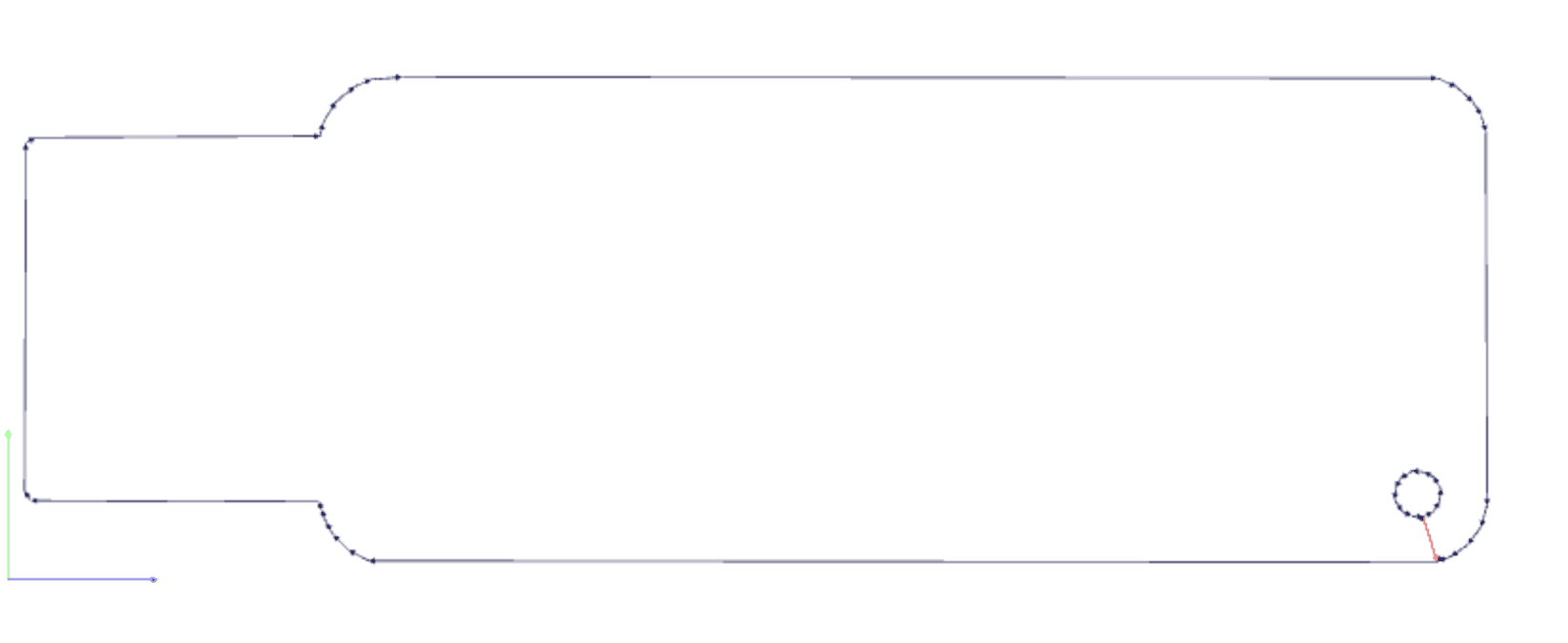
Now calculating this will produce a result similar to this:
MILLING
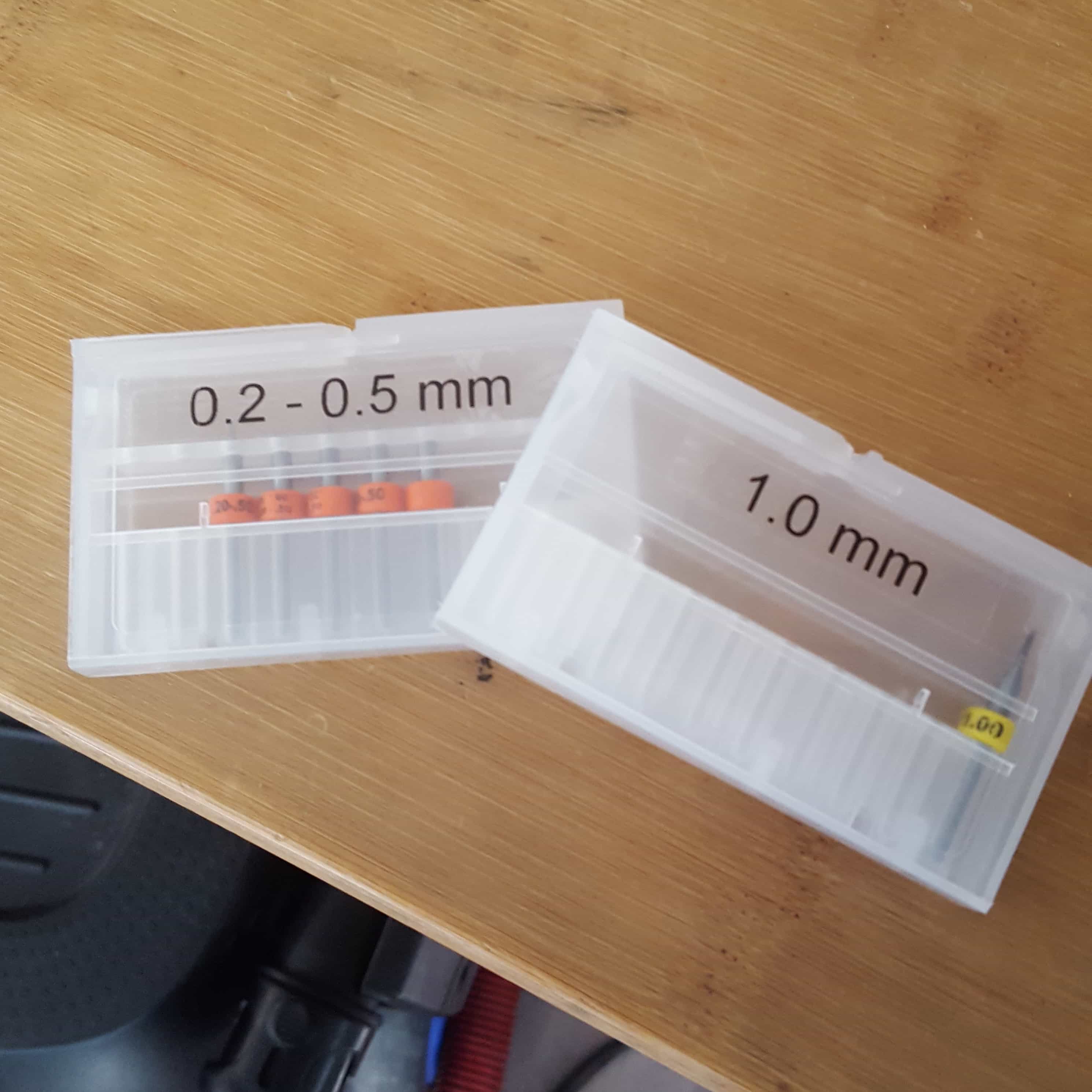
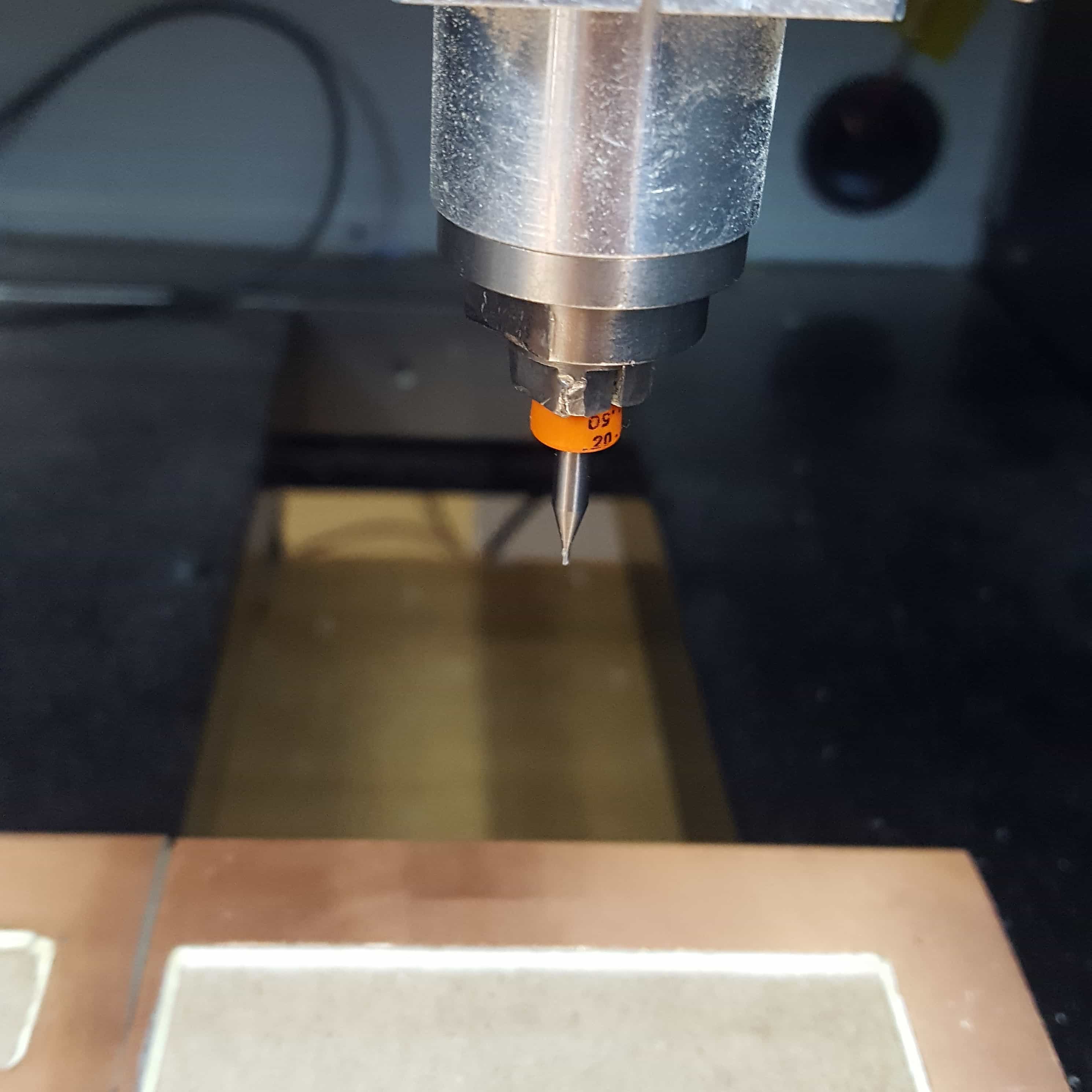
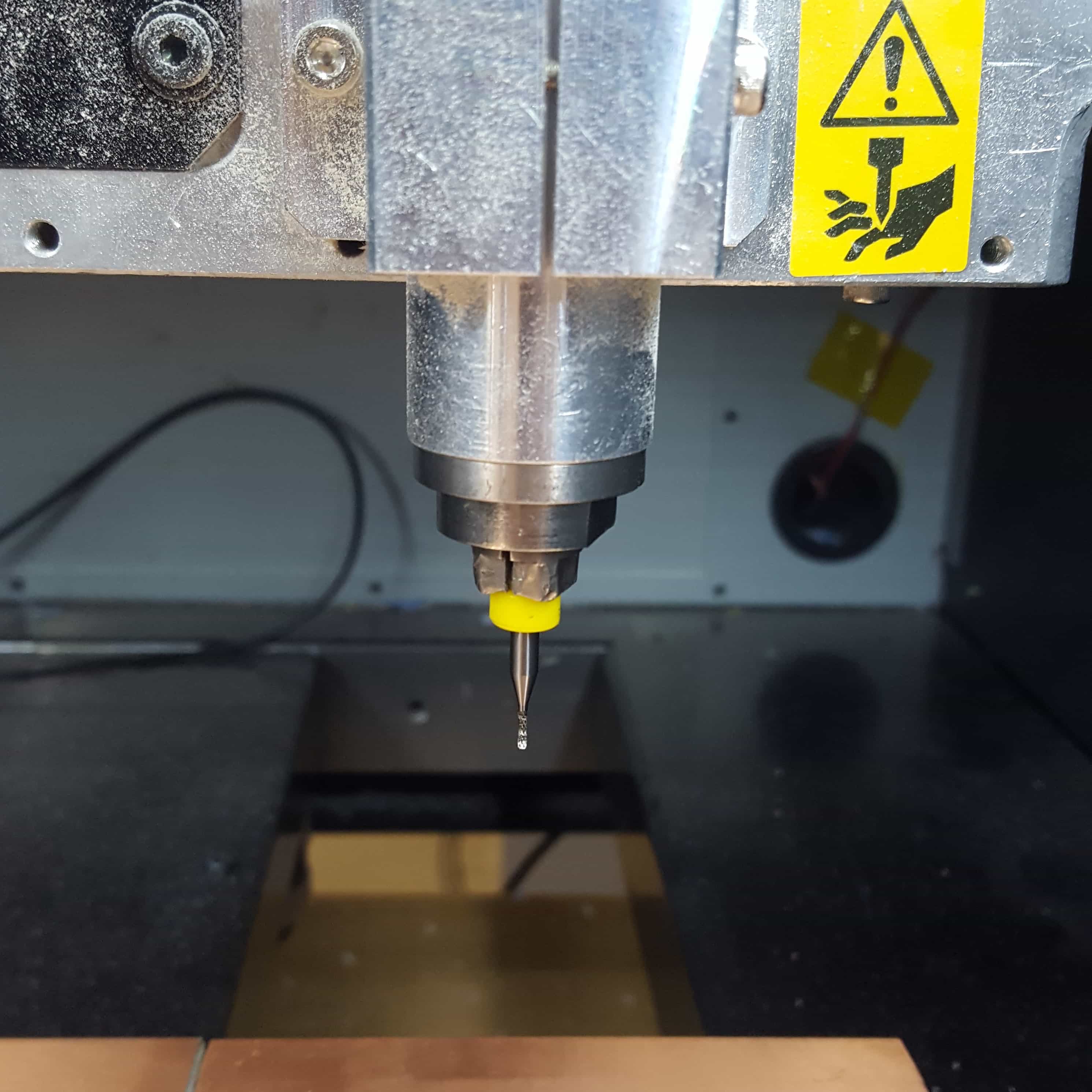
Following all these steps resulting in 2 gcode files that I copied onto the computer connected to the milling machine.The machine I will use a Roland MDX-40, a compact milling machine to mill boards but also molds and other stuff. To start milling I had to do some preparations, starting the machine is the first step. Now I had to look which drill head is attached to the milling machine. To mill the traces I will need a head which is 0.2-0.5mm.
I replaced the drill head, and set the xy-position of the milling head to a empty space on my board.
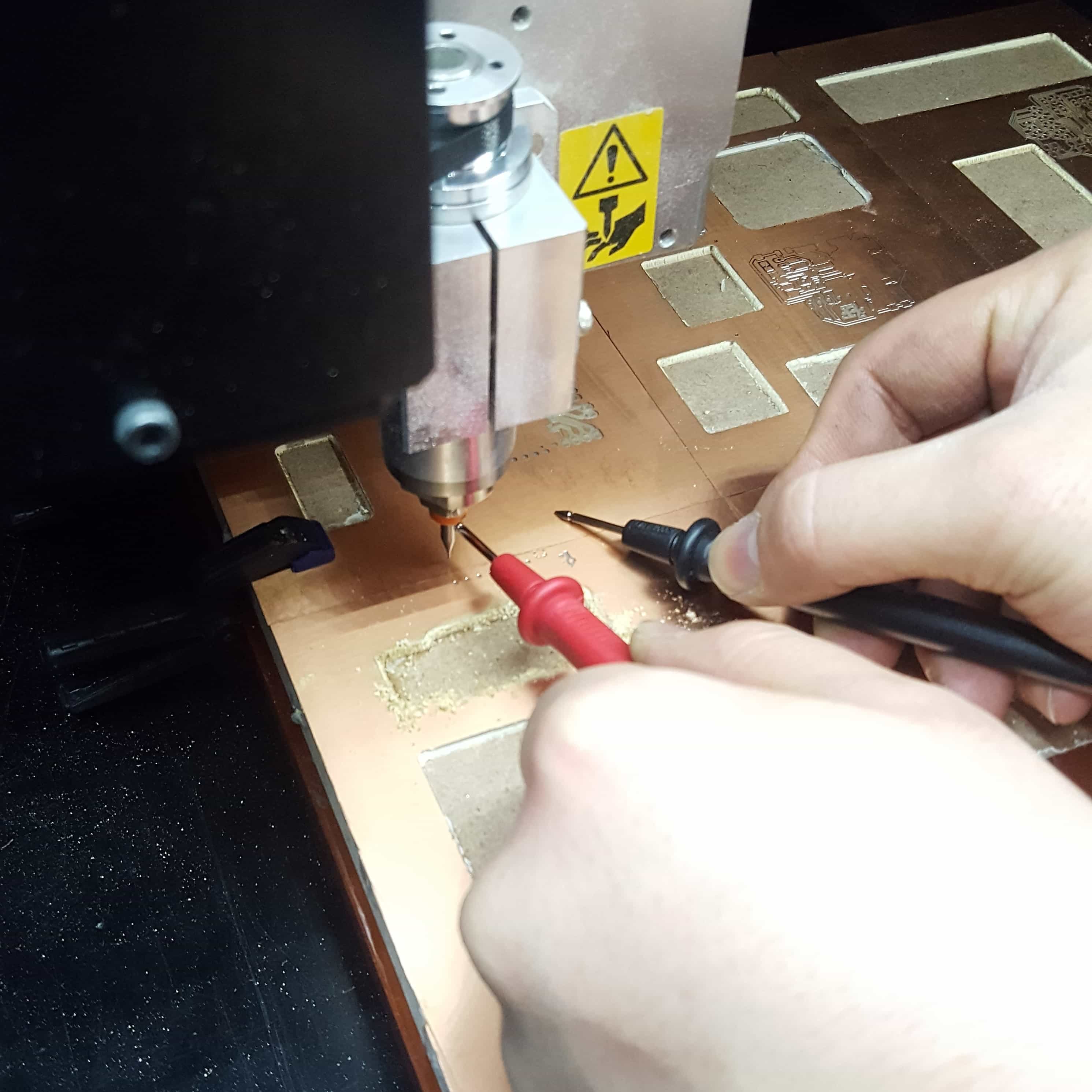
To get a clean cut with the right cut depth, we nee to set the z postition of the millinghead. There are different ways to do this. I personally use a mulitmeter to find out the exact spot where the drilling head touches the plate.
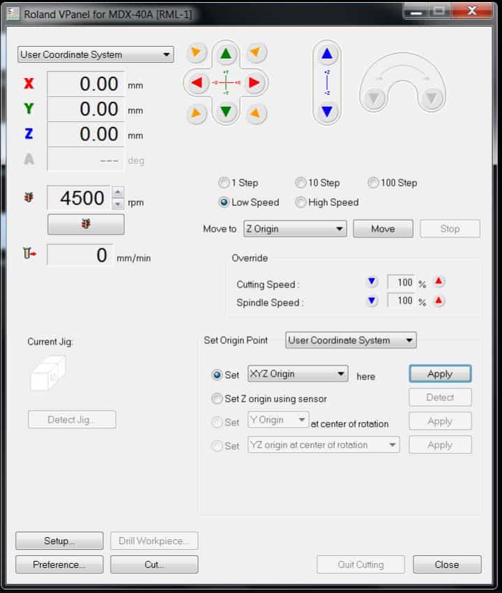
I will use v-panel as software for the milling job. VPAnel is a software from Roland made for the MDX-40A. By clikcing in the arrows on the top I am able to move the milling head on the x,y and z axis. When I'm happy with the position, I apply the coordinates by pressing on the apply button. It is also possible to first apply a specific axis for example the x and y only wihtout setting the z, so you can change the position of the head without loosing the z setting. When moving the head there is also the possiblity to change the moving speed by selecting the steps beneath the arrow buttons. "1 Step" will move the head 0.01mm only, increasing the steps will move the head faster.
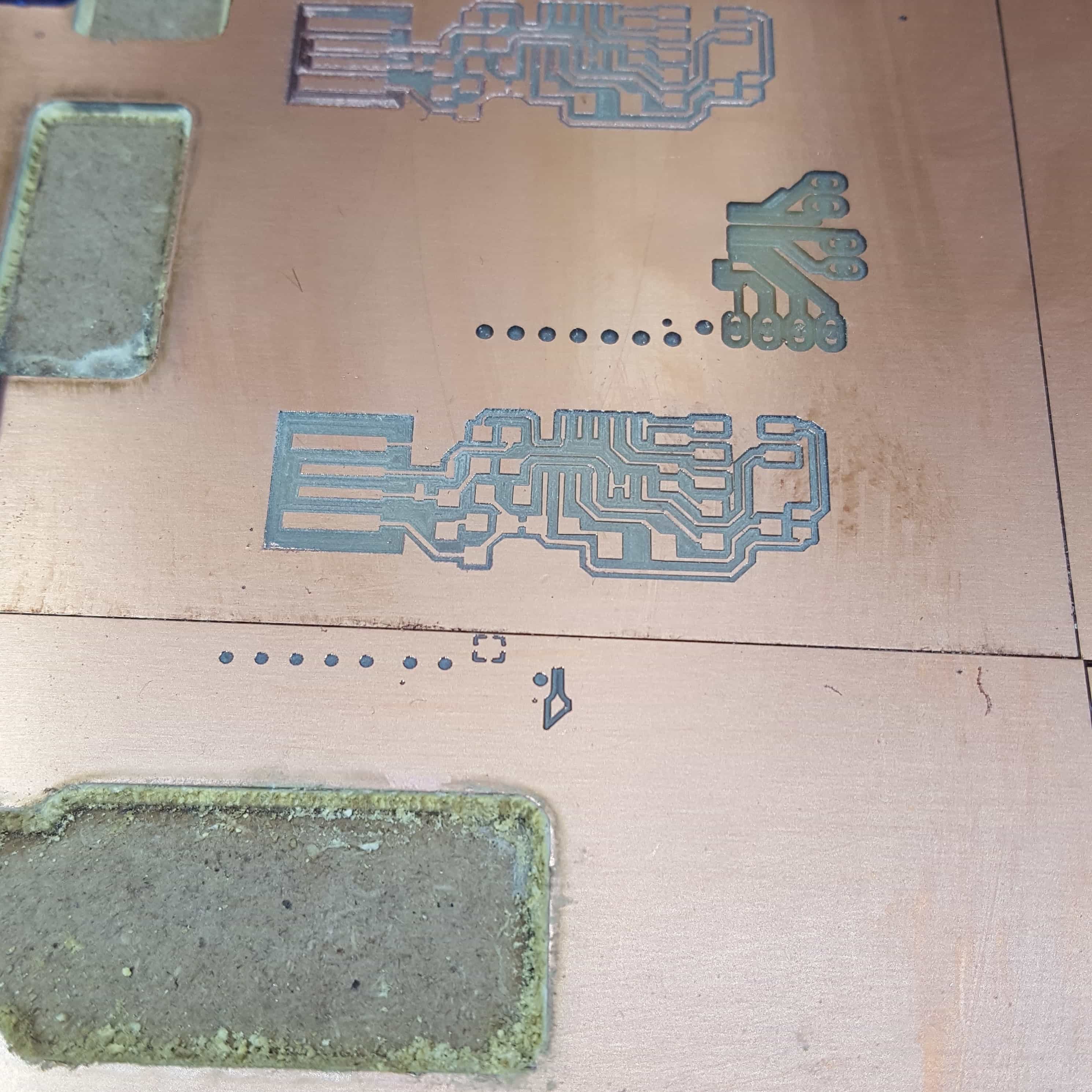
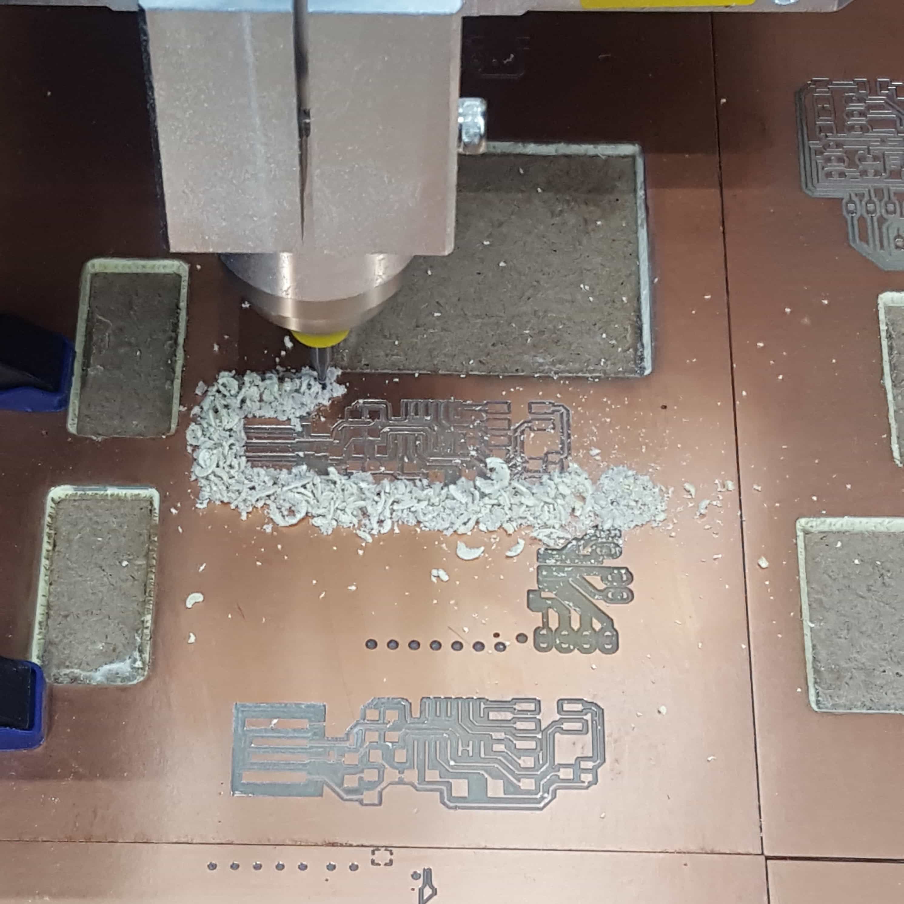
After that I can now start the milling process using my file within the given software. I just selected my gcode and pressed the cut button, to start the milling process. After the process is finished my result looked like this:
But I wasnt finished now, because my pcb still needed to be cutted out. For this I had to change the drill head to 1.0mm again.
Now I did the same steps as before, without moving the orign of the x,y axis of the milling machine,but only chaning the height of the head on the z axis. Now I just selected my other cut file and started the process again. The milling machine cuts out my pcb. Milling the pcb will take a lot of time, while a cutting job needs maybe 20 - 30 minutes getting the job done right could need several hours. The biggest issue I had was that the copper board we cut the pcb out ist mostly uneven, so if the right side is a few millimeters higher the traces will be cut too deep or wont be cutted anyway. Getting a feeling in how deep I had to cut took a lot of time, and maybe like 5-6 cutting jobs.
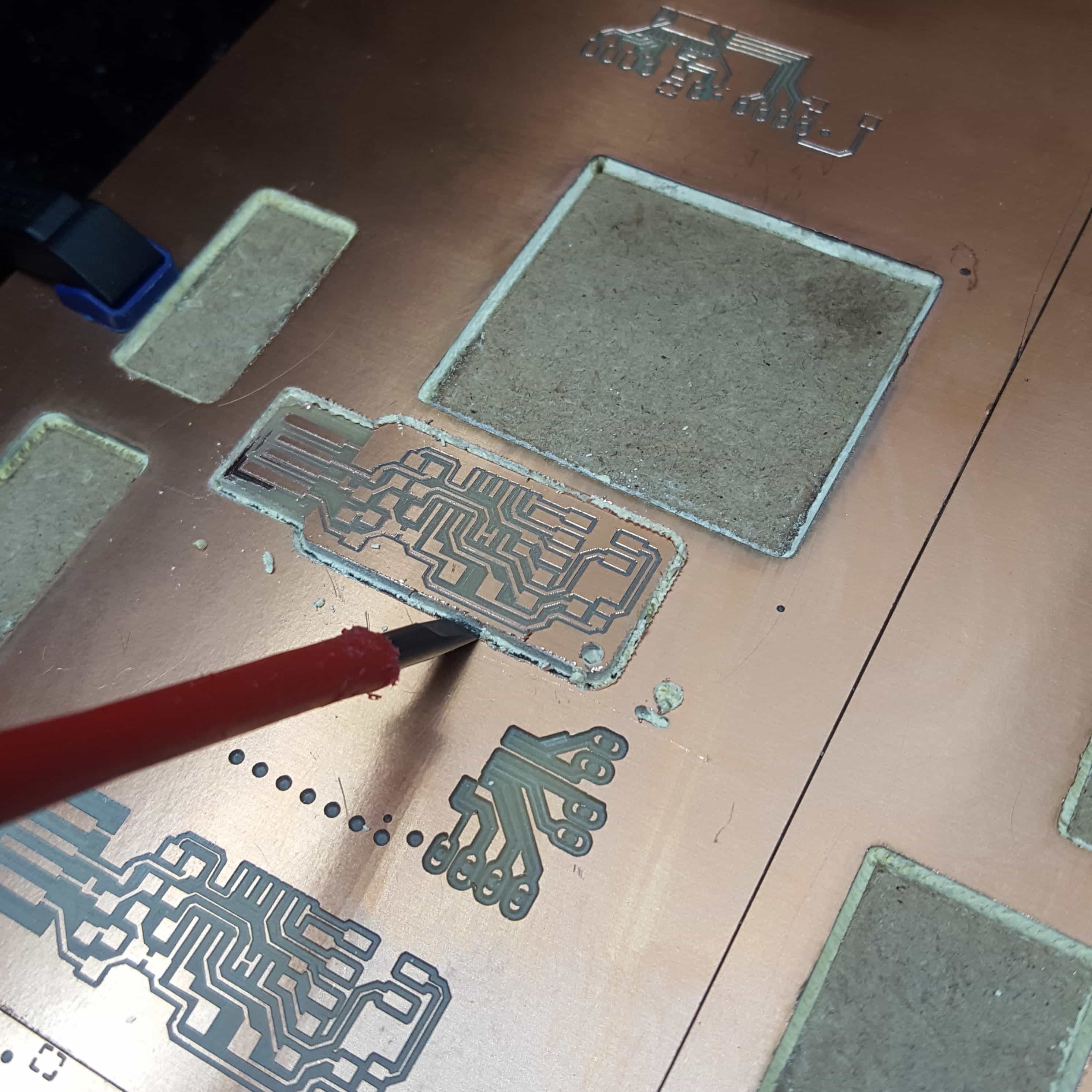
The only thing remaining now was get out the pcb with a tool (I just used a screwdriver).
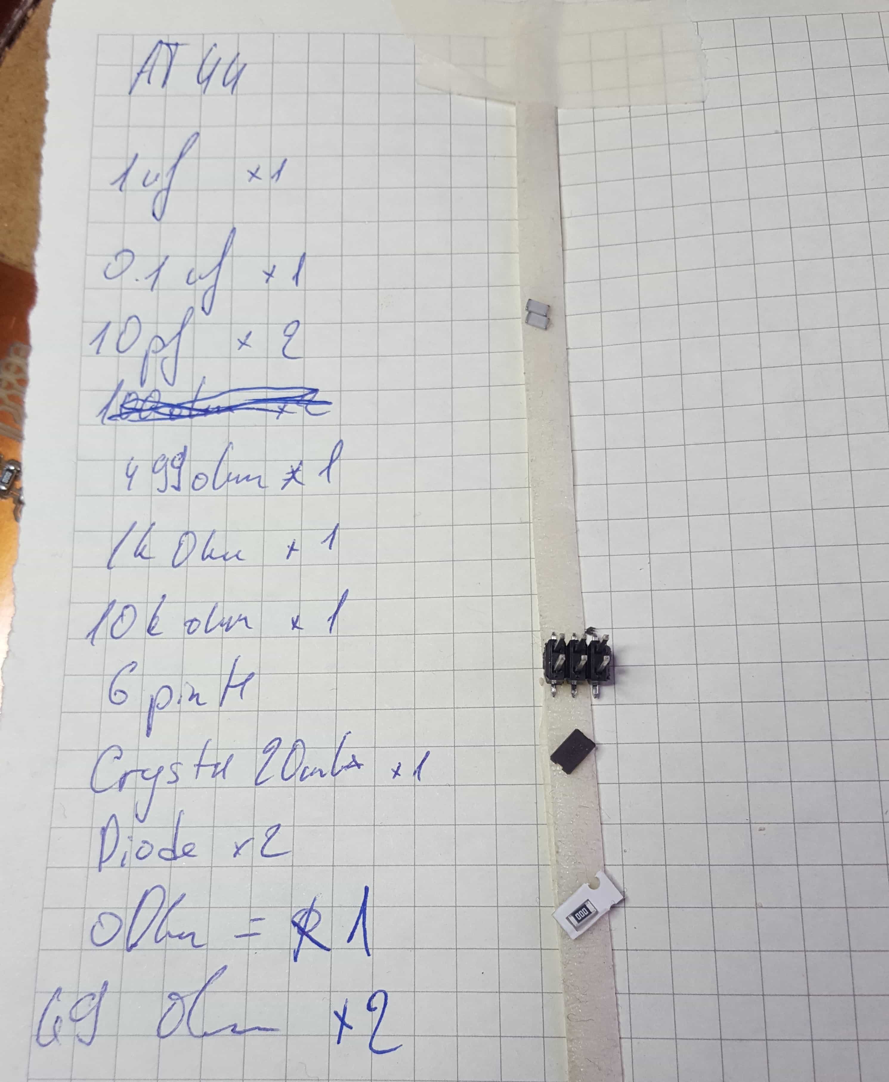
For the soldering part I prefer to do a list of parts I need first.
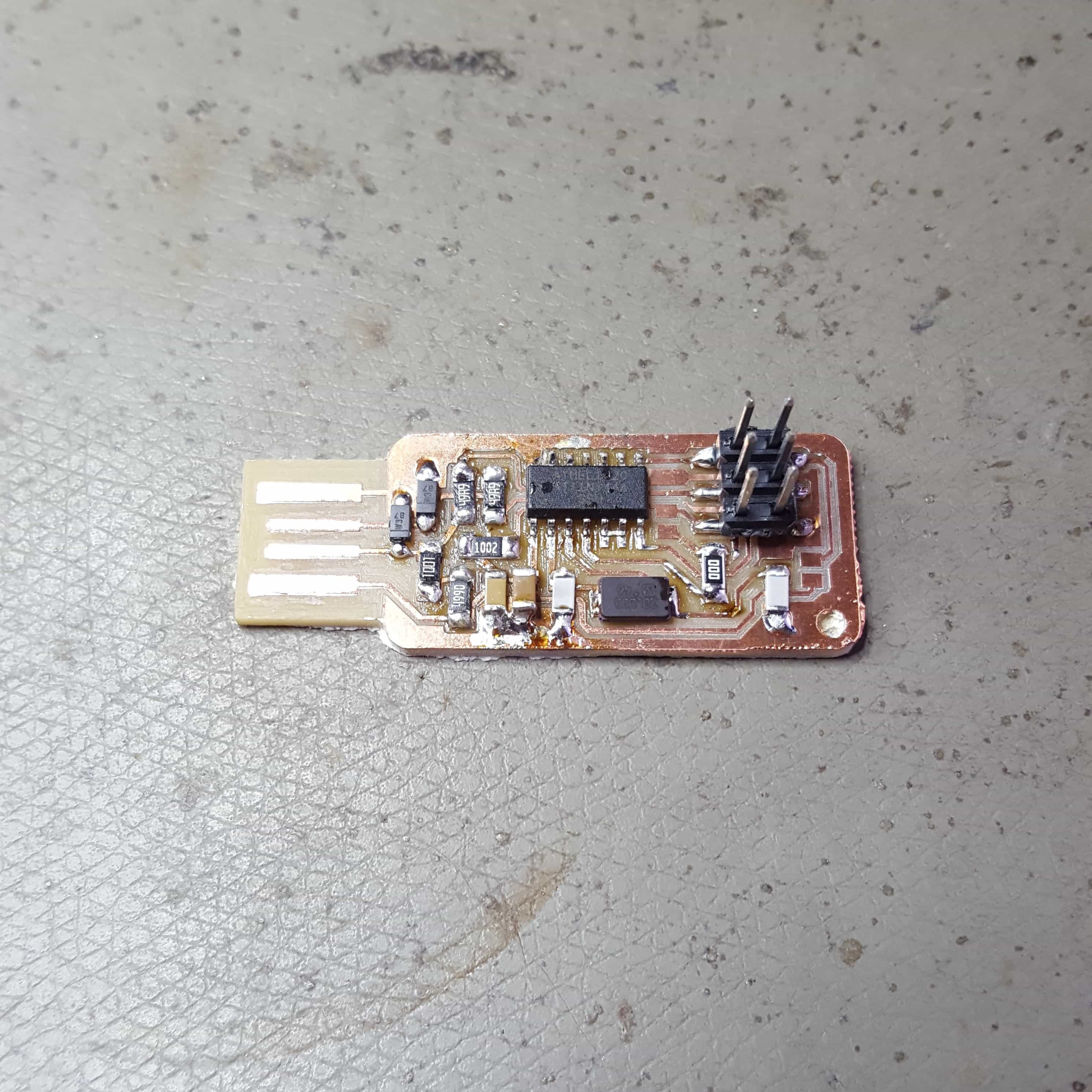
Soldering every part on the board takes a little bit of soldering skills and about 1 hour of time. I had not much experience in soldering specially not in soldering small smd parts. It was very hard to fix the components onto the right spot with a little amount of soldwire. Also my solderingspots were not very clean thats why I had to redo most of them, even though my soldering spots doesnt look the best they work and for a beginner I think it wasn't that bad .The finished pcb looks like this:
The last part is a little prgramming part. First things first I used a Arduino Uno with ISP programmed on it, to program my FabISPkey. I connected the arduino to my FabISP using jumnper cables according to this image.
When everything is connected, I started with downloading the firmware from the Fab Academy Electronics Production Page, and unzipped it. Using the terminal I moved to the firmware directory.
cd documents/firmware
I needed to make changes inside the makefile, to open it just type nano into the terminal.
nano makefile
Now I added follwing line, for adding the port of my Arduino(your port may be different):
AVRDUDE = avrdude -c stk500v1 -P /dev/cu.usbmodem1413101 -b19200 -p $(DEVICE)
I just added the line underneath the two similar ones. The only thing required is to comment the two line above and paste my own line.
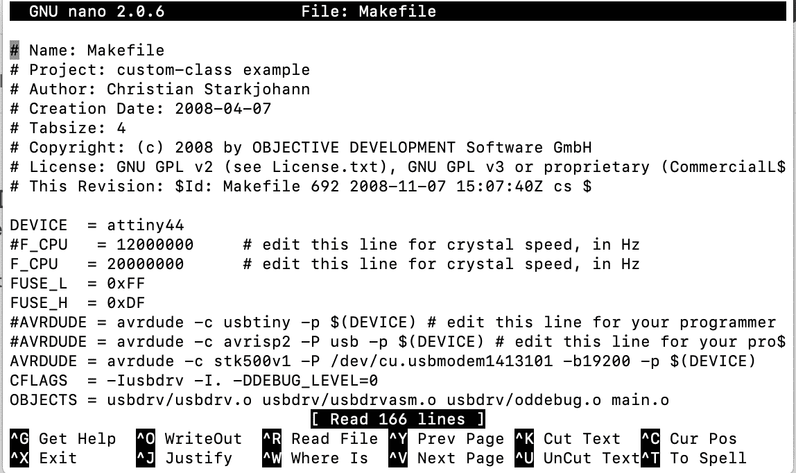
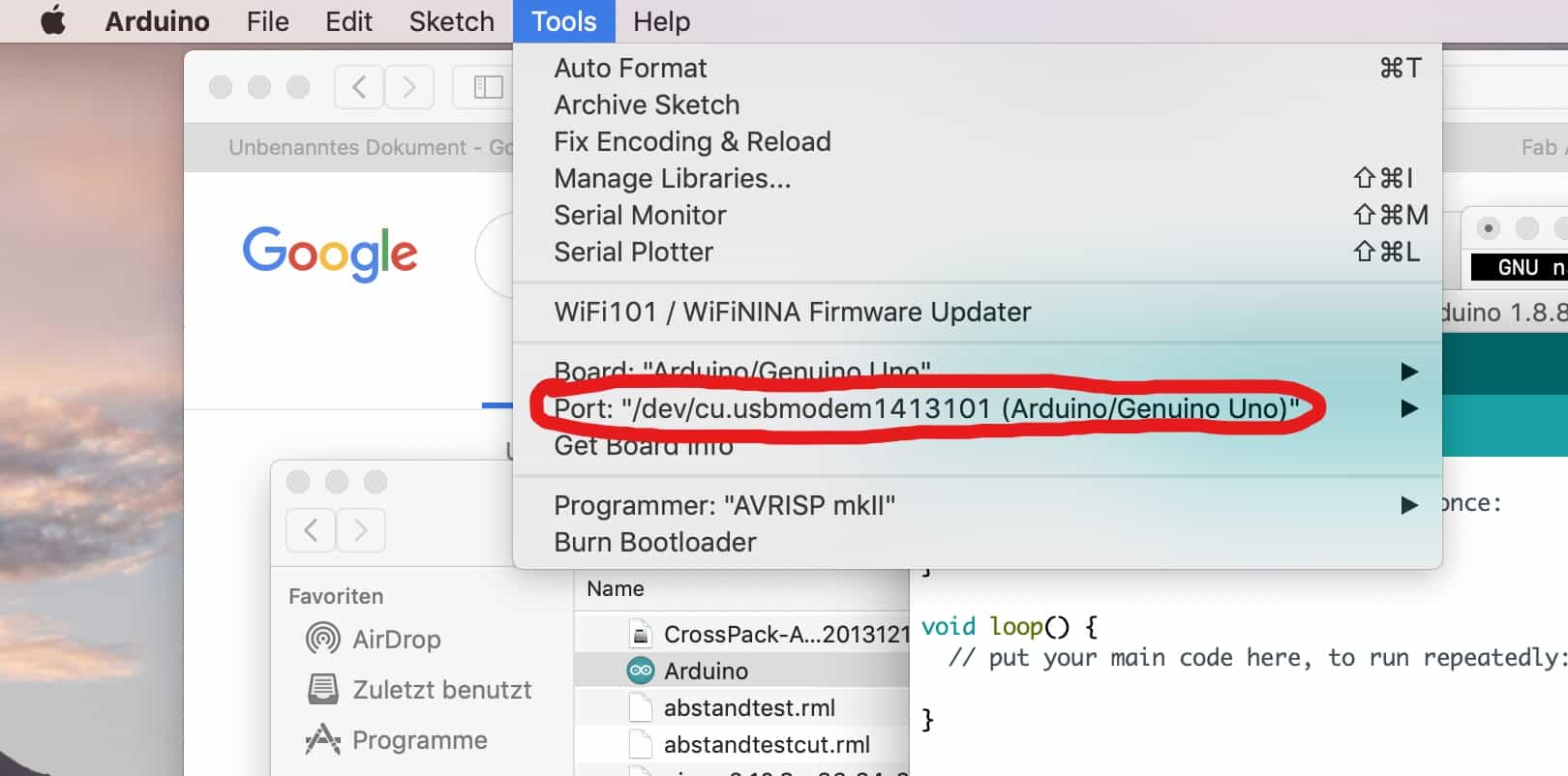
The Makefile should look like this, you can clearly see where I put the device line to. TIP!: To get to know your Arduino port just open the Arduino IDE, go to Tools in the top bar, look after the port of your Arduino and paste it into the line of code: AVRDUDE = avrdude -c stk500v1 -P /dev/"PUT_YOUR_PORT_HERE" -b19200 -p $(DEVICE)
I saved my makefile and the rest was just typing in a few comands into the console.
make clean
After that
make hex
then
make fuse
and finally
make program
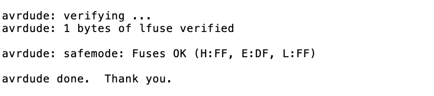
When everything worked right, I got this message inside my console.
The only thing left was checking if the FabISPKey works, so I plugged it into the usb port of my computer and looked it up in the plugged device list.
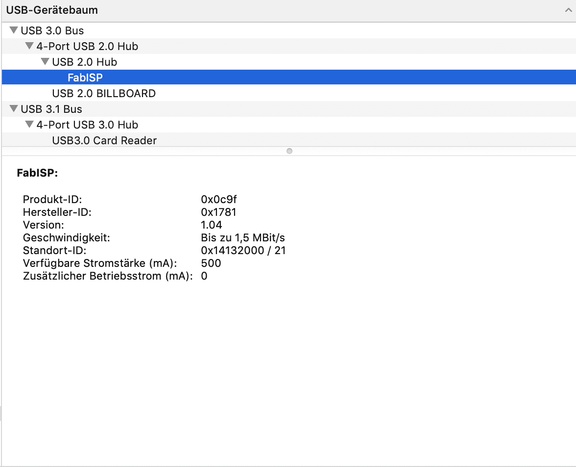
As you can see it recognises the plugged device as a FabISP.
PROGRAMMING A BOARD
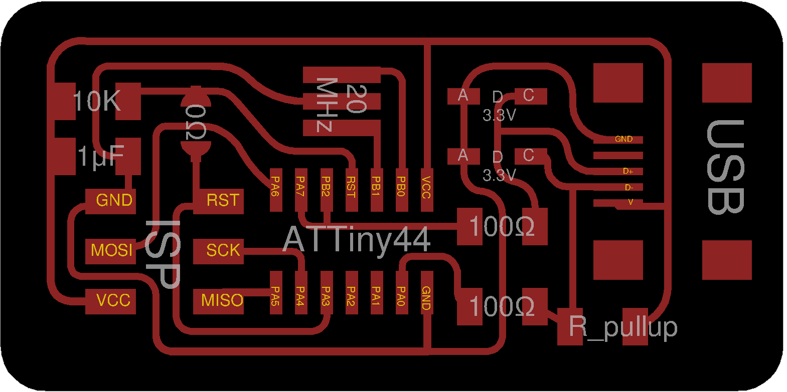
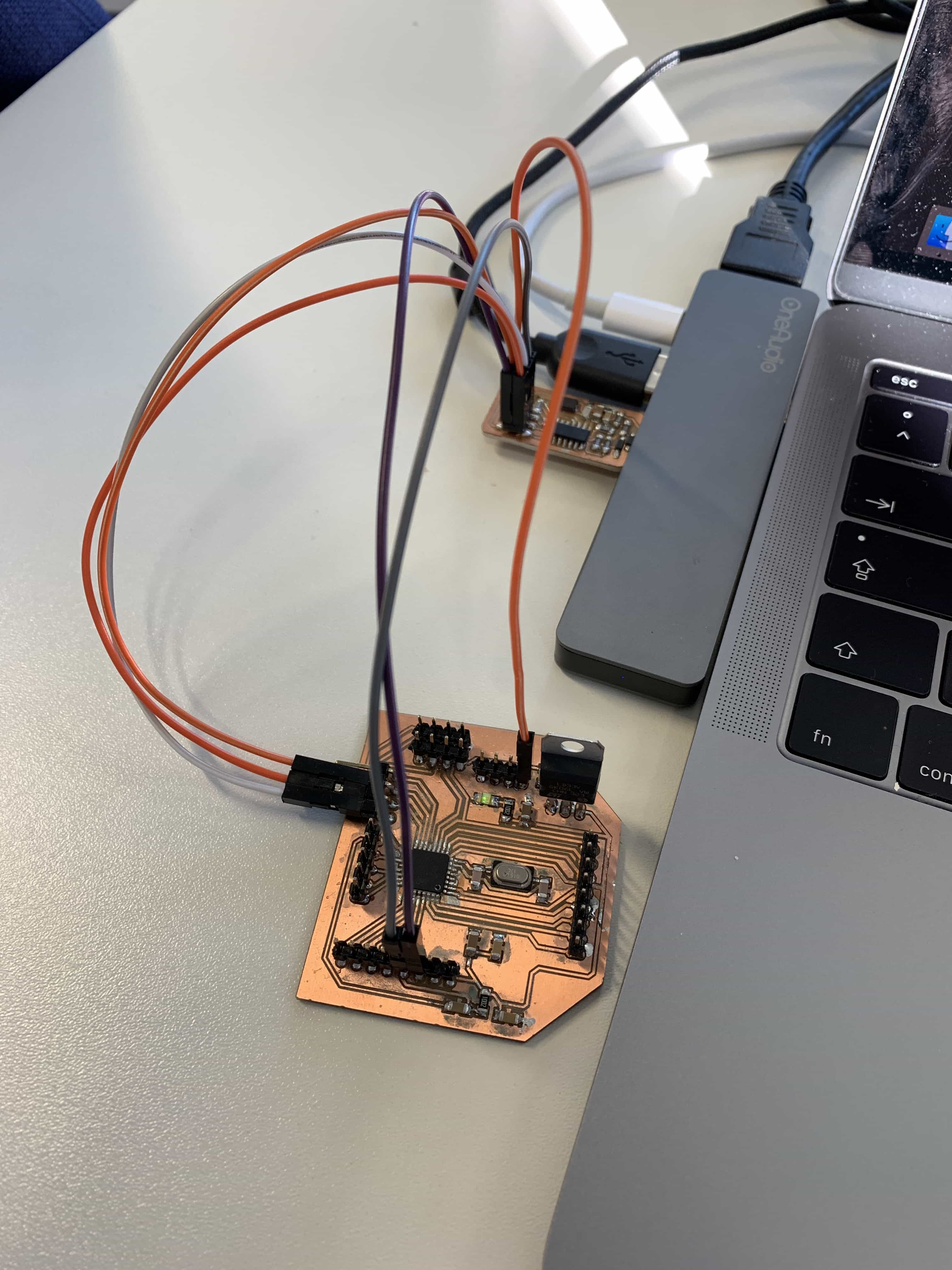
To test if the programmer really works I programmed a attiny44 board which I made in week 7. Make sure to connect the board to the fabisp properly
-MOSI to -MOSI
-MISO to -MISO
-SCK to -SCK
-RESET to -RESET
-GND to -GND
-VCC to -VCC
To burn fuses, I needed to download the firmware.zip and extract it first. Also I needed the .make file and the .c file for the attiny44. You can get both files from the embedded programming assignment of the fabacademy schedule. Move to the folder that was just extracted.
ls desktop/fabISP_mac.0.8.2_firmware //just in my case!
Now we can start generating the necessary files to install the firmware for the MCU:
sudo make -f hello.ftdi.44.echo.c.make
Then go on with installing the generated firmware by calling the program:
sudo make -f hello.ftdi.44.echo.c.make program-usbtiny-fuses
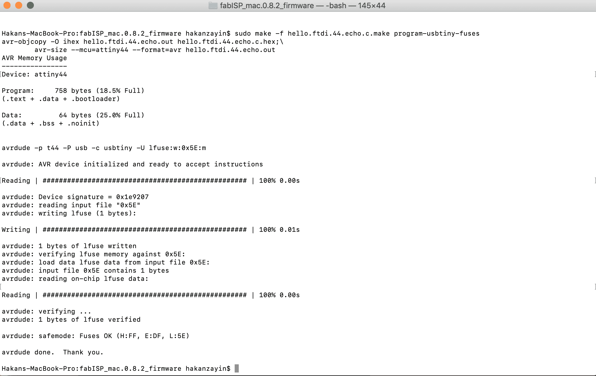
The bootloader is burned and the board is ready to get programmed now. The fabisp works.