In this weeks assignment I had to redraw the echo hello-world board and add at least a button and LED to it, using a software for circuit board design.
I have used Autodesk's Eagle for this assignment. Egale is a application with schematic capture, printed circuit board layout, auto-router and auto-router and computer-aided manufacturing features.
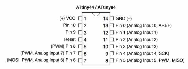
The Microcontroller I have used is the ATtiny44 with a external 16Mhz crystal. We already used this microcontroller before in the fabisp-key.
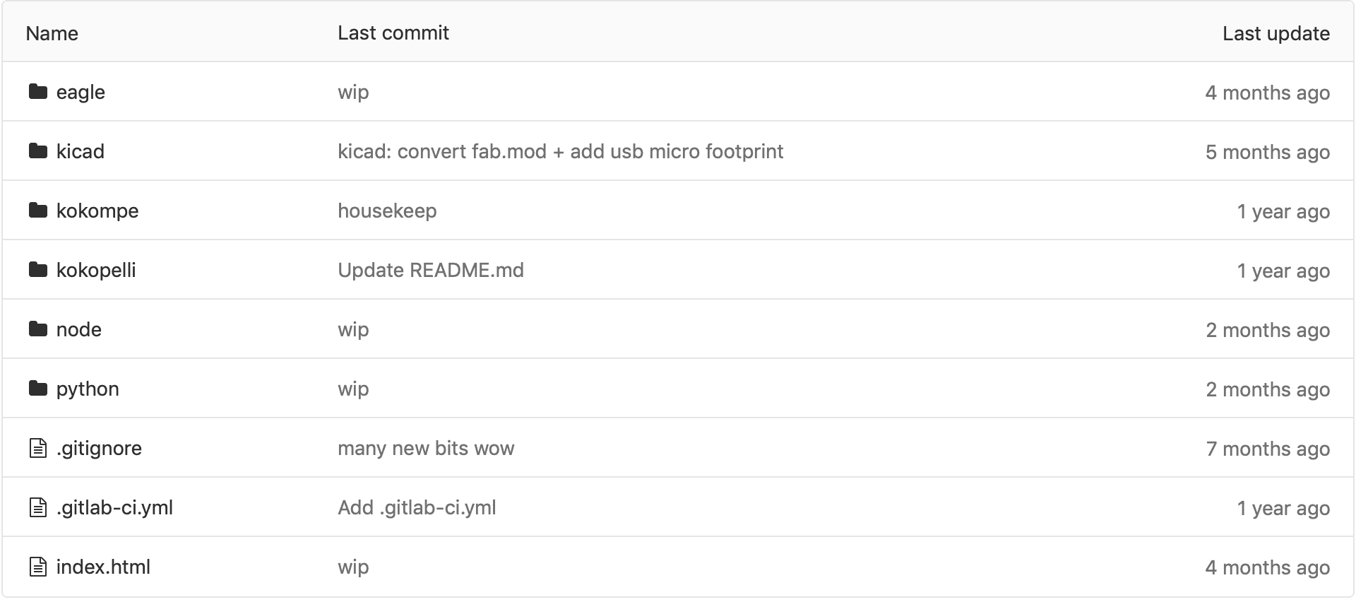
In order to work with Eagle, I have added a library to it. Eagle has build in libraries already, but for more customization I have used the
Fab Academy Libraries. Just select the software you are using and download the library, in my case eagle.
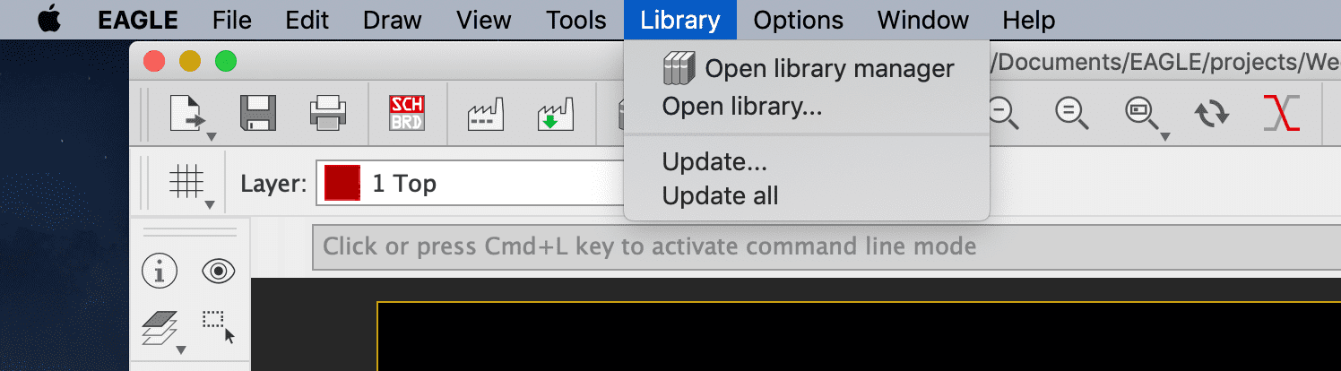
Inside Eagle I had to import the library first to use it. So I have openend the library manager clikcing on library at the top bar.
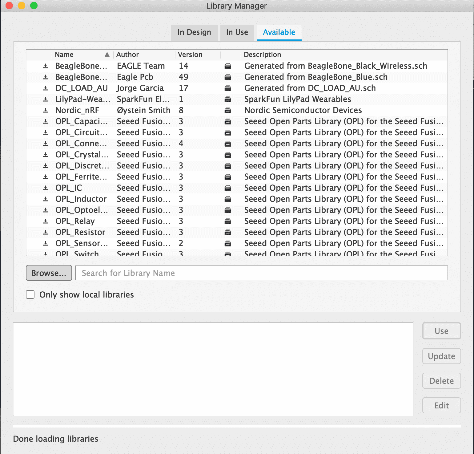
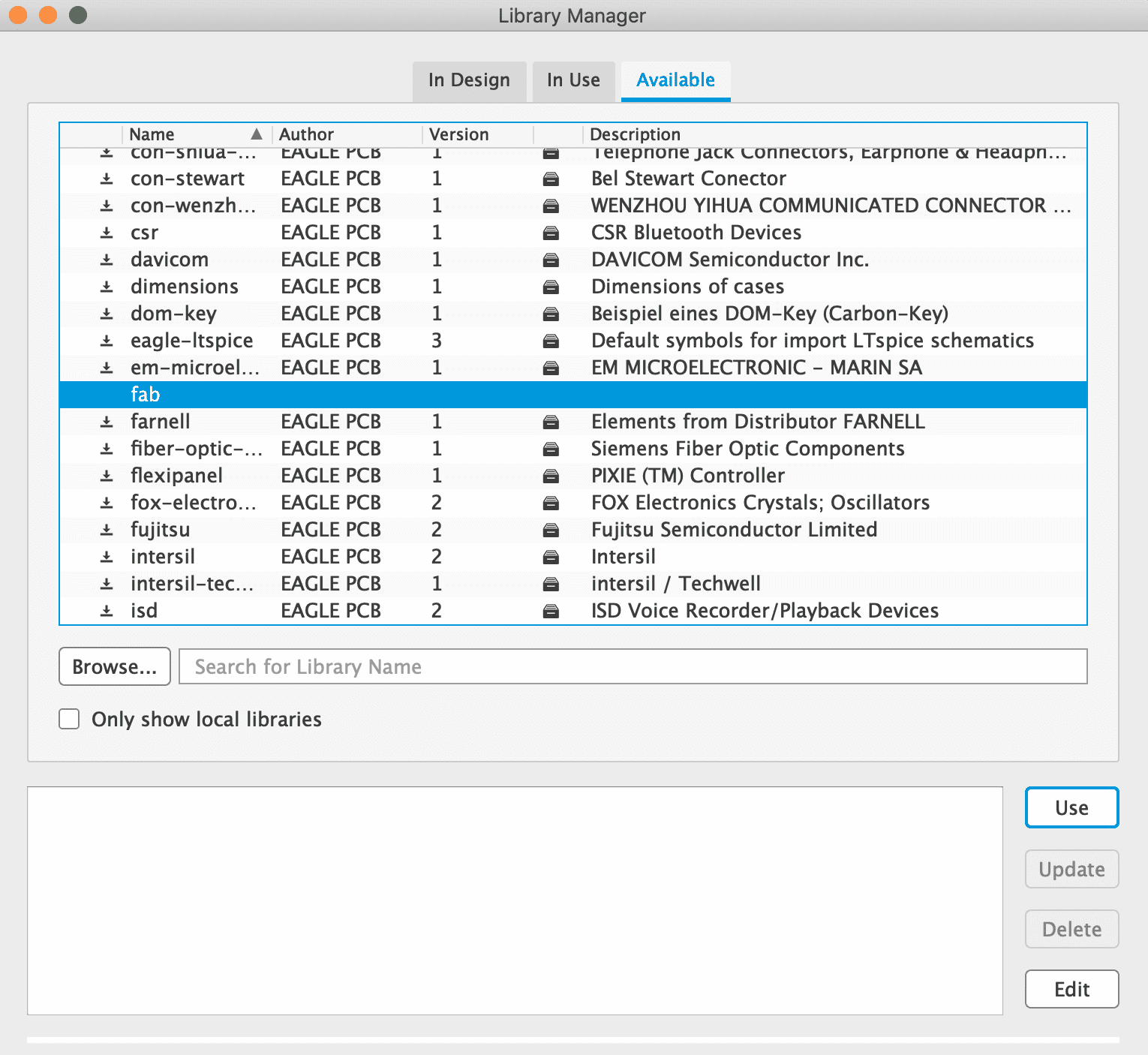
In the library manager I navigate to "available" and click on the browse button.
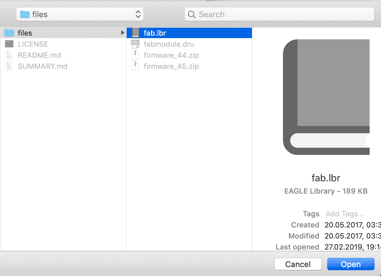
Now I had to select the library I have downloaded, in my case the FabAcademy library.
After I have selected the library, it appears in the file browser. The last thing I had to do is to select the "Fab" library and click on the "use" button.
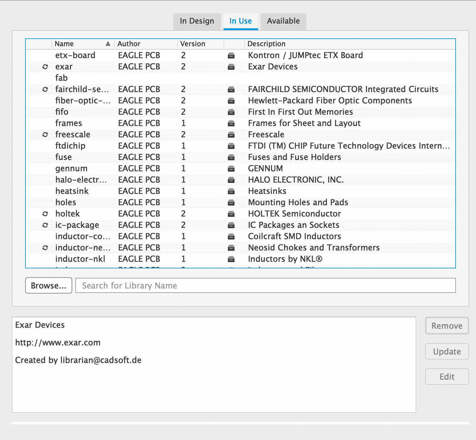
When evrything worked fine the library should appear in the "in use" library
Adding parts to the schematic
The schematic window is used for the logic behind our board. Adding parts and connecting them together is essential to produce a board. In the schematic, the desing of the board plays no role. Every part and connection added to the schematic will be on our board, so adding useless parts is not recommended.
Now to add a part to our schematic, I had to click on the "add part" symbol on the sidebar.
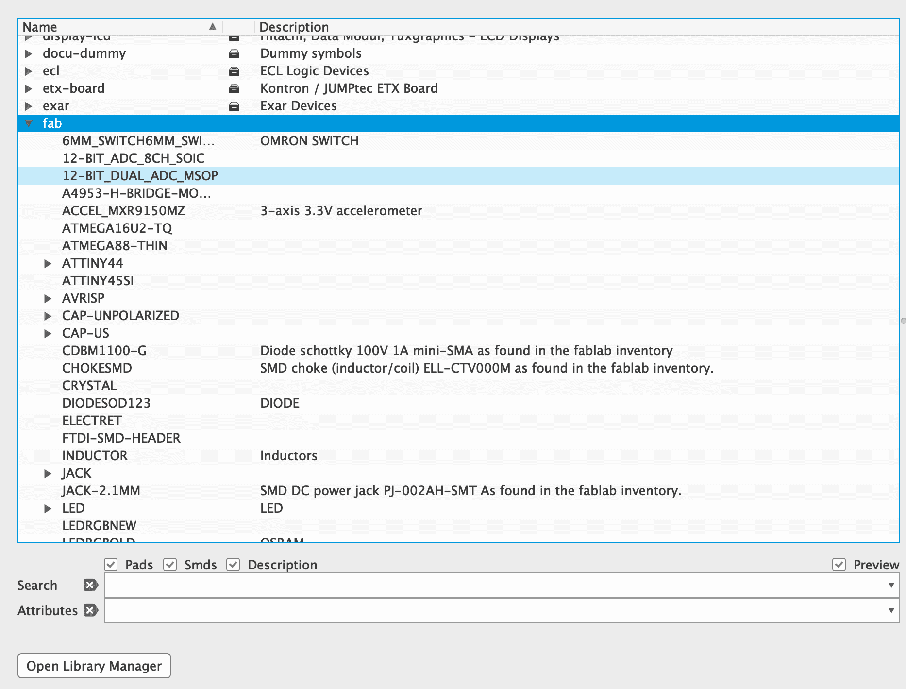
Clicking on "add" will open a library window. That is where I will use the added library. When searching for "Fab"
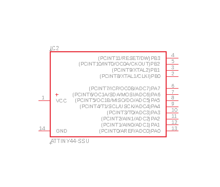
To add for example a ATtiny44 I just clicked at "ATTINY44" and selected the pin layout I needed. When clikcing on the part I get to my schematic layer and can simply place the part anywhere I want.
When adding the part you can see the pin layout of the attiny44, it is especially good for people with not much knowledge about microcontroller because it makes connecting the right pins together much easier.
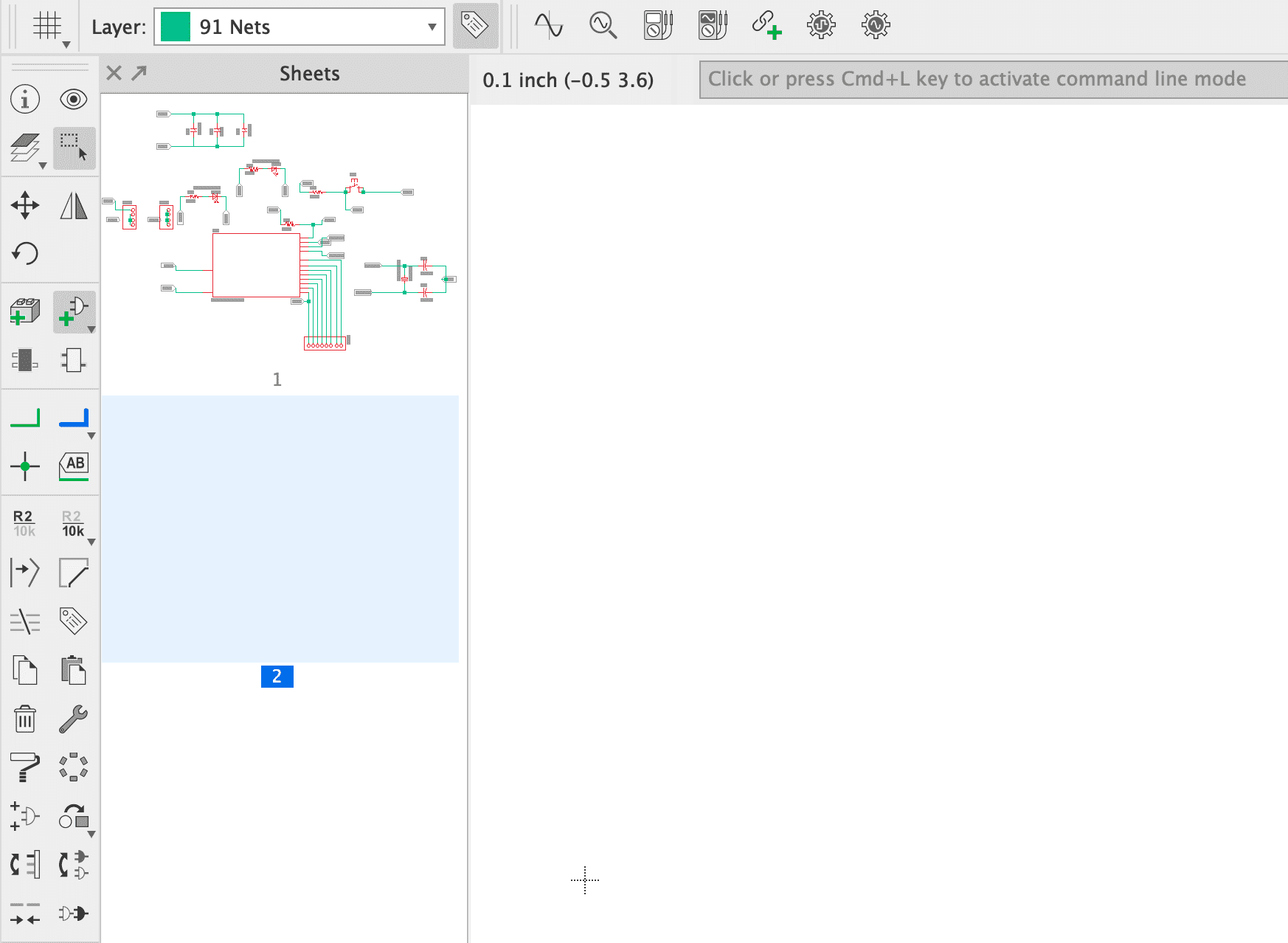
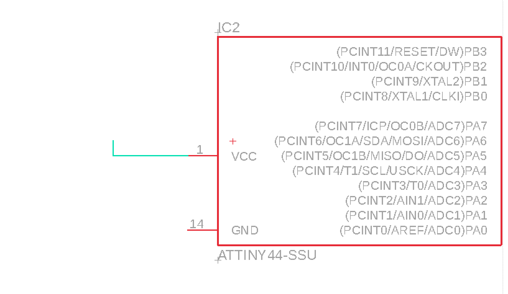
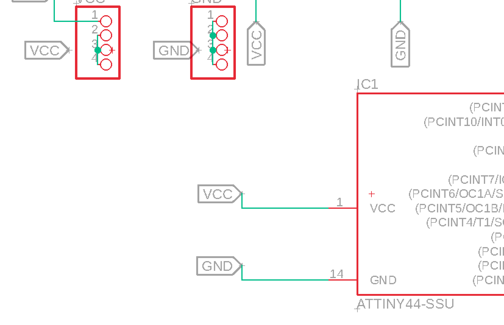
Now to start I had to create Nets and give them a label. The system is very easy to use. For example I have a "VCC" (Power) and a "GND"(Ground) pin on the microcontroller. If I want to connect these to pin headers each, I just create a short line using the net tool.
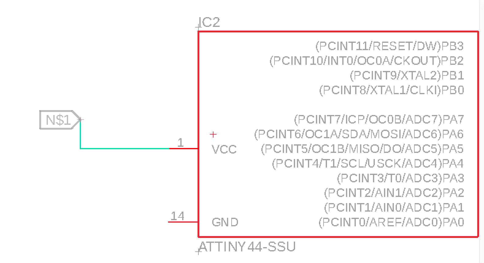
Then I give the net a label, using the label tool.
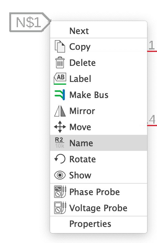
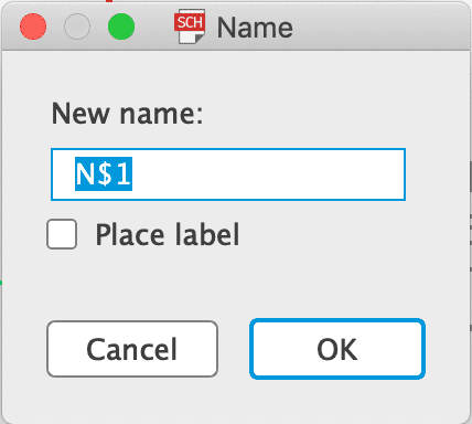
Chaning the name of the label is necessarily to connect parts together. So If I label the "GND" pin "GND" and want to connect pin headers to the ground, I have to label the pin headers also with "GND". To do this I just right click on the label and select "Name".
If I do this with both the pin headers and the "GND" pin, eagle asks wether I would like to connect them. Clicking on ok will connect the pin headers to the ground pin.
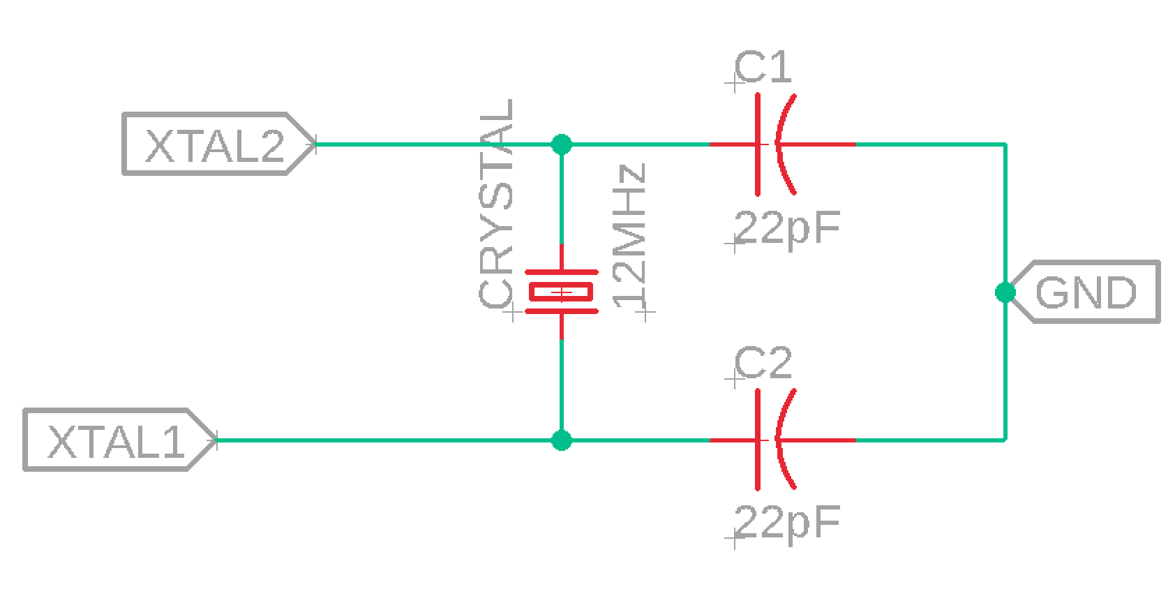
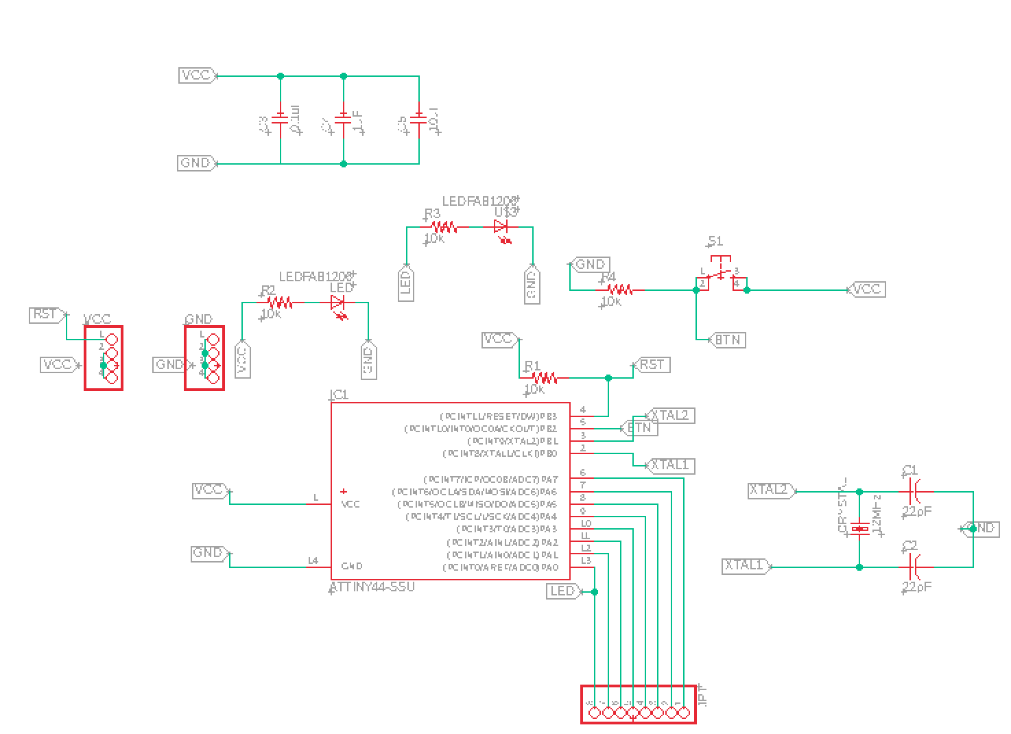
The microcontroller will use an external 16Mhz crystal. I have connected the crytsal to two 22pF capasitor.
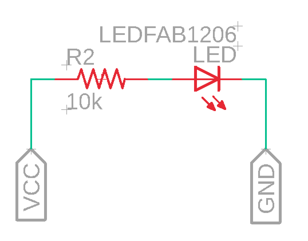
Also I have added two smd leds, one shows wether the pcb is powered and the other one is connected to a free pin on the microcontroller. In the schmeatic I just connected the led to ground and power. Between power and the led I had to put a 10k resistor to reduce the voltage coming from the vcc.
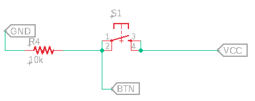
Another task was to add a button to the board. I have used a simple switch. I have also put a 10k resistor between the button and power.
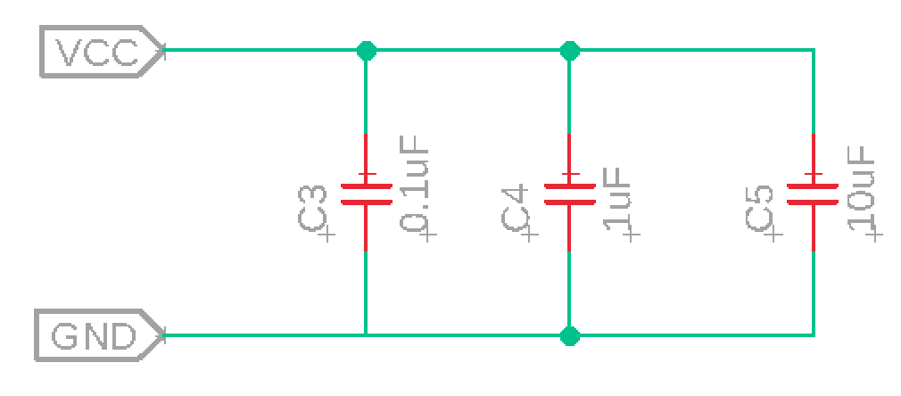
To have a more stable power signal, I have put three capacitors between power and ground.
1 x 0.1uF
1 x 1uF
1 x 10uF
Boarddesign
My finished schematic looks like this.
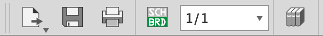
To build up the board design, I had to switch to the board window. To do this I simply click on the SCH/BRD icon at the top bar.
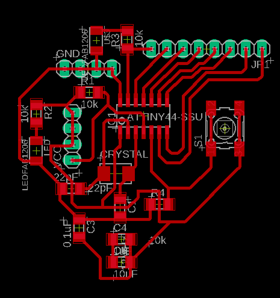
I dragged the parts into the workspace and began to create routes, to create the routes I had to click on the create route icon at the sidebar. On the topbar I have the chance to change the route thickness. It is recommended to choose thicker routes because it will get harder to mill the routes, when they are very thin.
It took me a long time to figure out a way to put the parts on the board in a right way. The problem was that placing one part could lead to blocking another parts route. After trying it out and redoing it a few times, I got to a desing which in my opinion not perfect but acceptable.
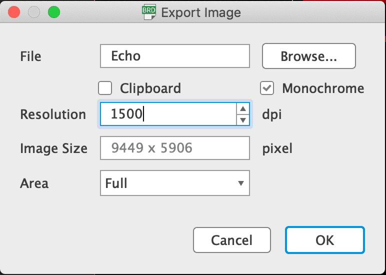
Now I had to export my board, I have done this by navigating to File -> Export -> Image. I have to export it as png to create a g-code within the
Fabmodules website.
For further information on how to use the fabmodule webiste check my recent assignment for electronics production. The export settings are as following.
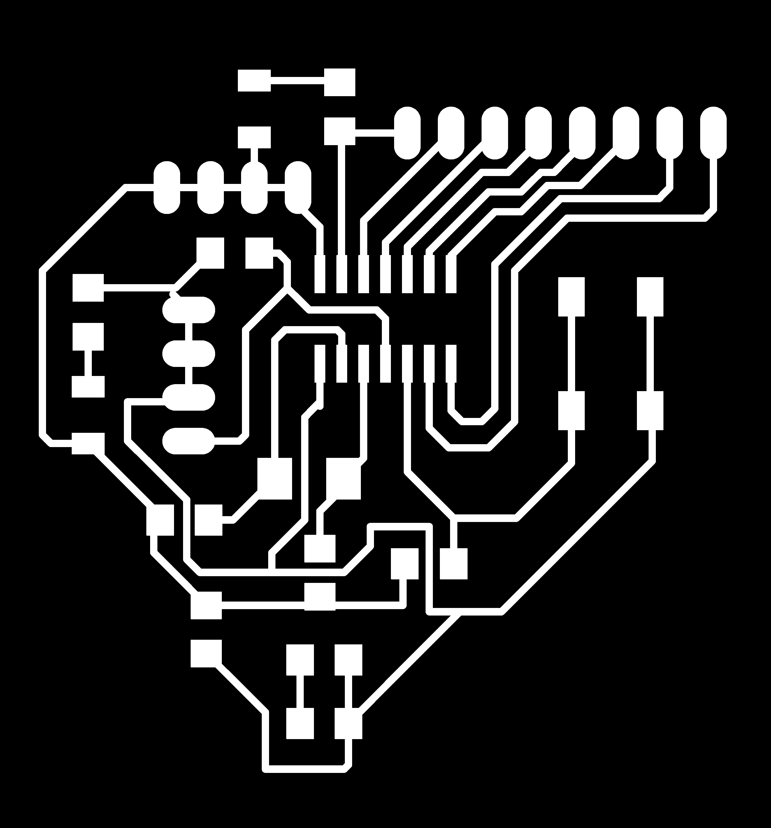
After cropping the unused space from the image, I personally use gimp for it, my image looks like this.
also I did the cut out with gimp filling the middle with white.
Attention! the images are scaled down and can't be used for any cutting for the original files scroll down to the download links! Thank You !!
I will not explain the milling and soldering process, but you are welcome to read my last weeks assignments, where I explained everything.
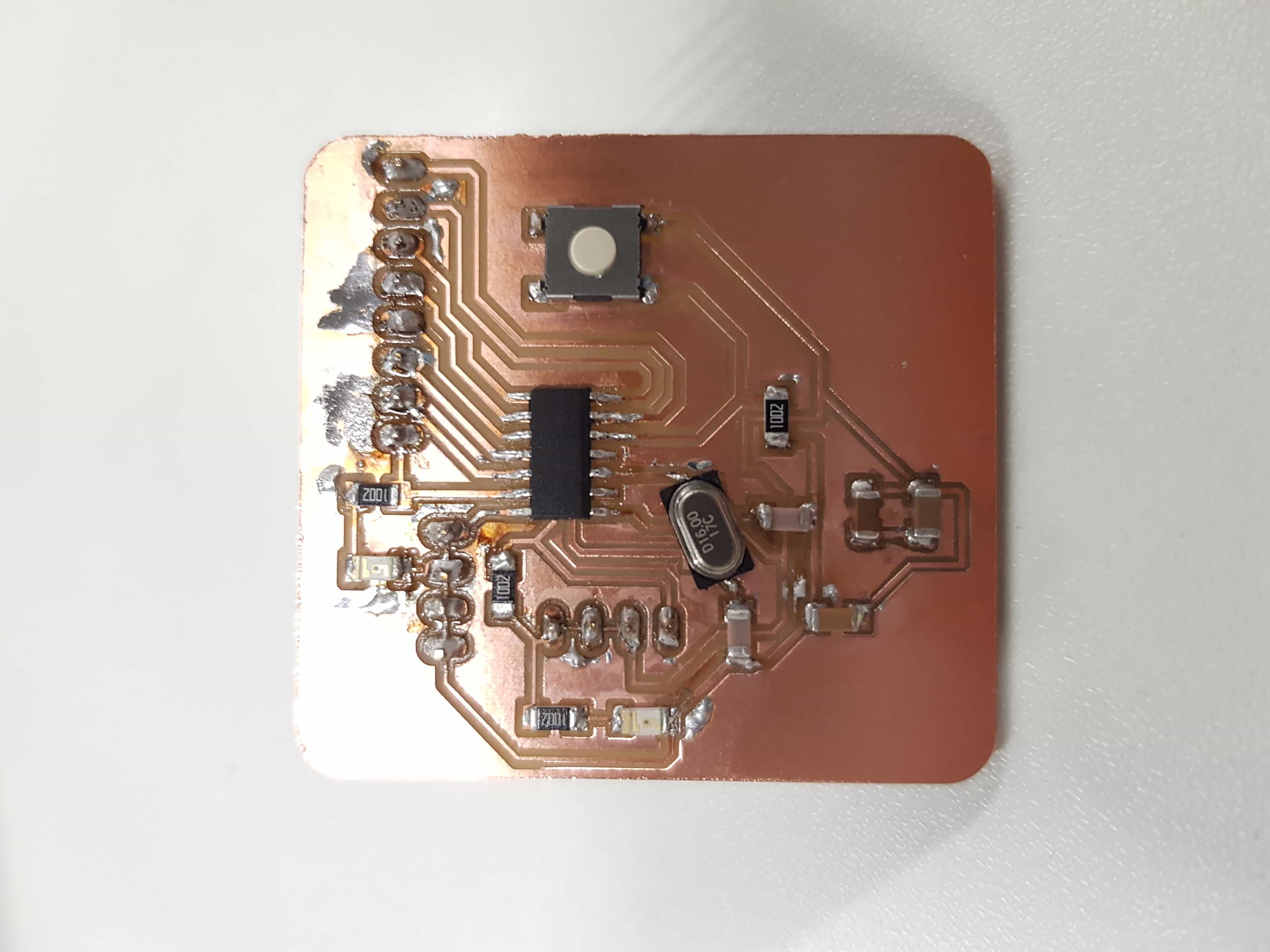
My finished board looks like this.
Programming
The only thing left is getting the bootloader on my board. To do this I used an arduino uno, but you could also use a fabisp key. Note that without a ISP you wont be able to load anything on the board.
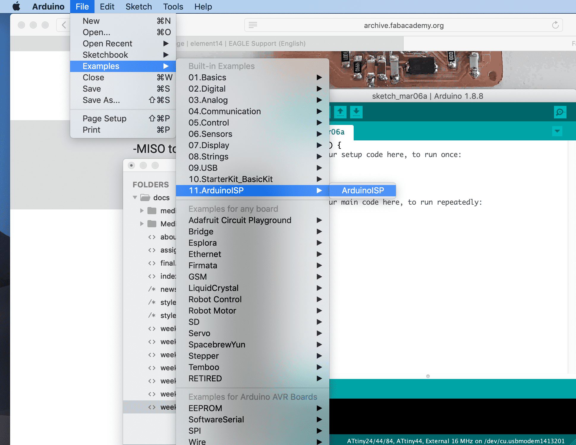
First thing first I uploaded the ArduinoISP on the arduino, it is located in the example sketches.
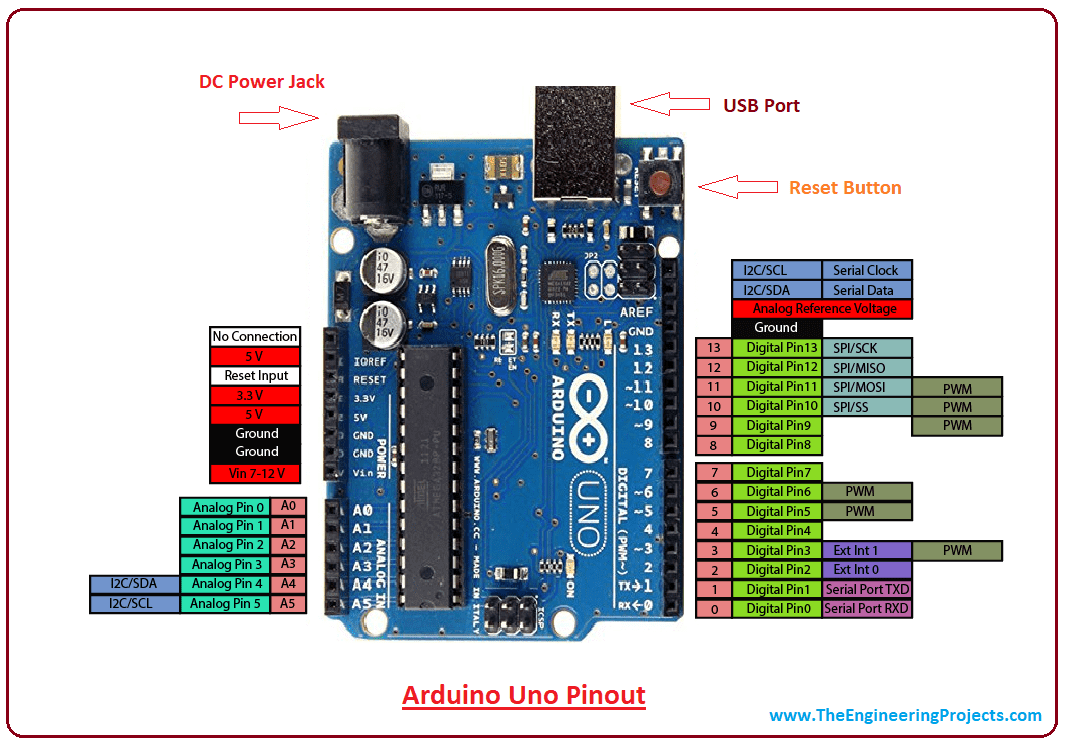
Now I connected my board to the arduino. Make sure to get the right connections.
-MOSI to -MOSI(pin11)
-MISO to -MISO(pin12)
-SCK to -SCK(pin13)
-RESET to -RESET(pin10)
-GND to -GND
-VCC to -VCC
When everything is connected right, I am now able to burn the bootloader on our board. To do this you maybe first have to install the library for the ATtiny44
ATtiny library.
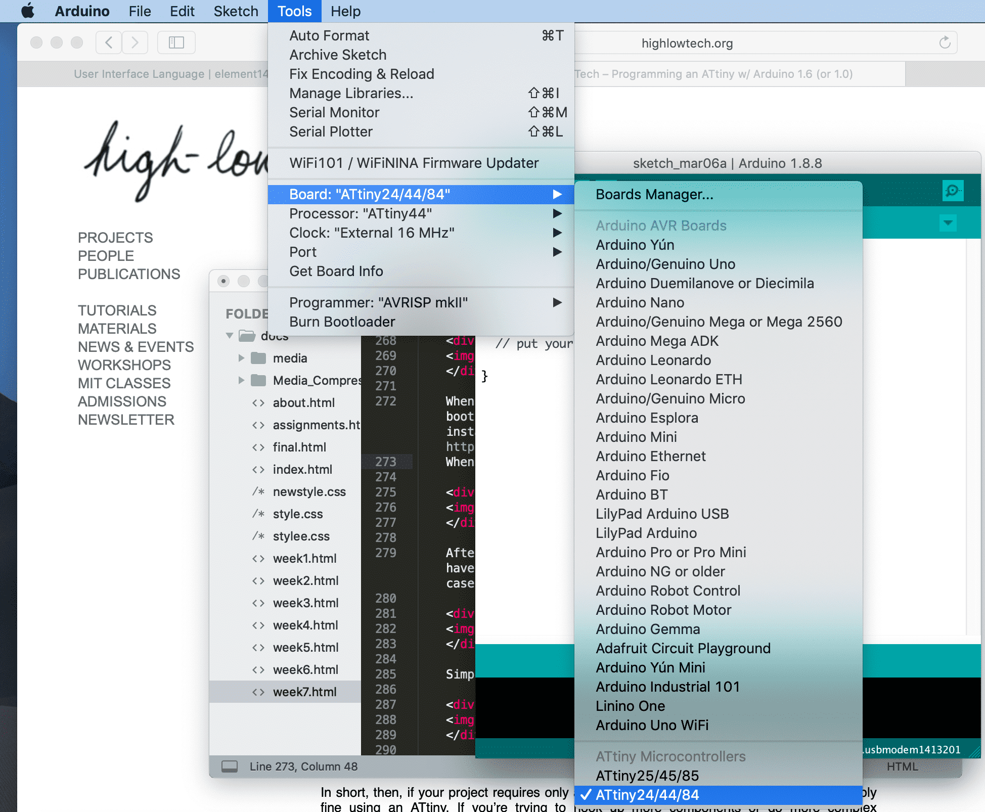
When the library is installed just choose "ATtiny 44" under Tools -> Board -> ATtiny 22/44/84
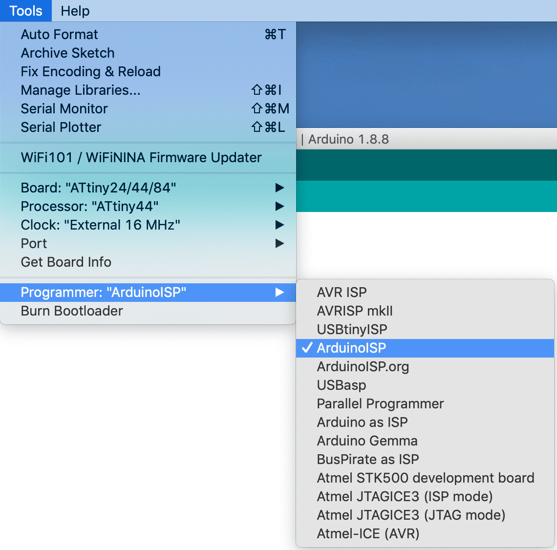
the last thing to make sure before burning the bootloader is to check if the clock setting is right, as mentioned before in my case 16Mhz. Also if the right port, in my case the arduino and if "ArduinoISP" is set as programmer.
Note: If you use a different device as an arduino your programmer will possibly be another one!
Burn the bootloader and you are reeady to go.
Now I am able to load a program onto my board, for testing I simply uploaded "blink" and here is the result


