For this weeks assignment we measured the power consumption of an output device. The documentation can be found here.
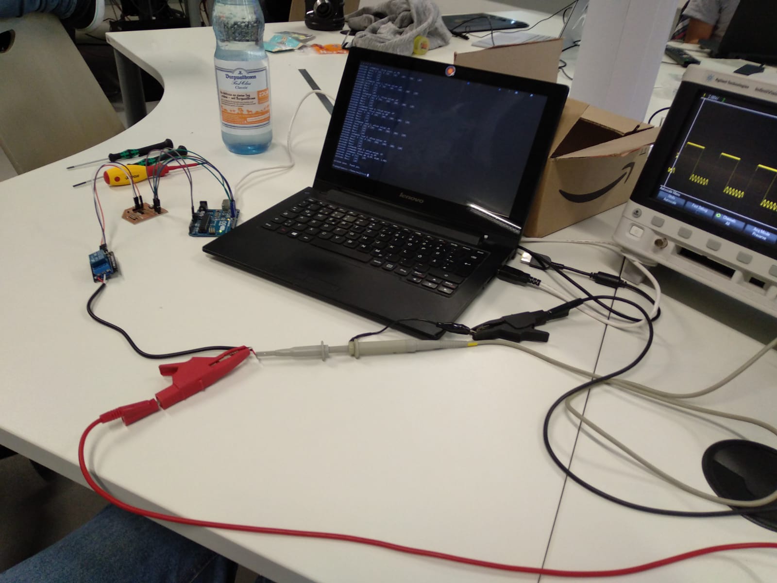
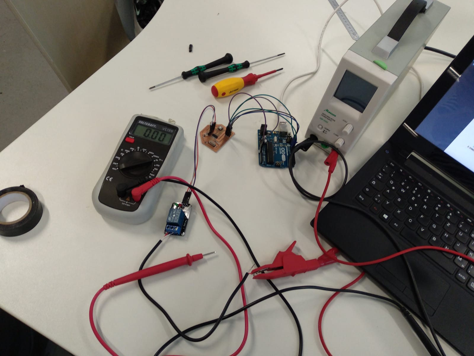
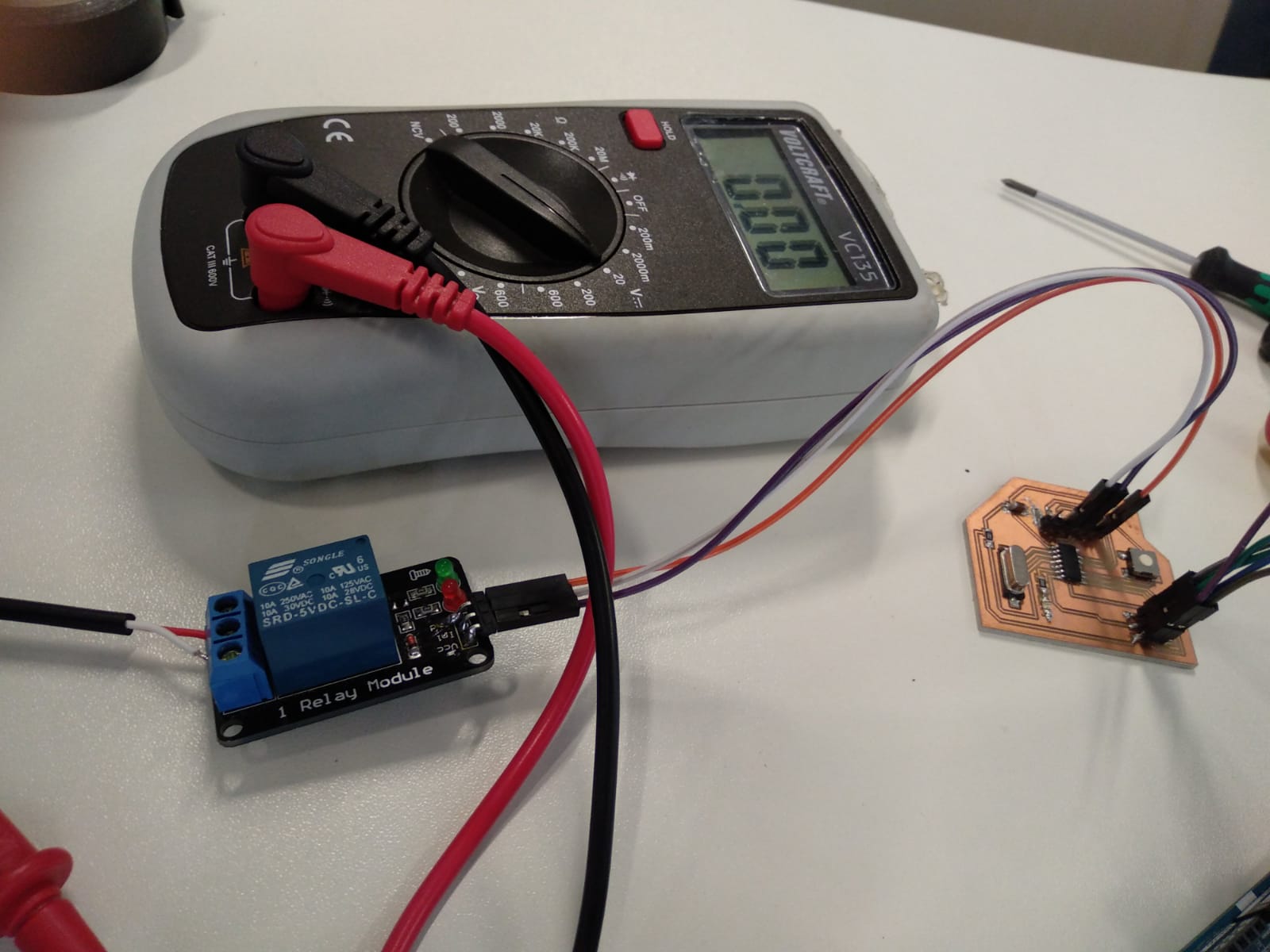
For this assignment I used a relay as an output device. I connected the input pin to pin PA0 of my board, as well as controll VCC and GND. On the other side I connected a power supply.
The datasheet of the relay shows that either the middle and the left or the middle and the right connection can be used. The relay will act like a switch.
I used the board from the Electronics Desgin assignment. On that board I exposed almost all pins of the microcontroller, so it can be used as a general purpose prototyping board, similar to a Digispark, just with an ATTiny44 instead of 45 and looking more like a house for some reason.
As the Relay only needsI programmed the board to switch rapidly using the following code:
#include <avr/io.h>
#include <util/delay.h>

int main(void) {
   DDRA |= 0b00000001; // initalize as output
   while (1) {
       PORTA ^= 0b00000001; // bitwise xor to toggle the state
        _delay_ms(120);
      }
   }
the datasheet of the relay says 30 operations per minute are the maximum value, so actually this is a little too fast. _delay_ms(500); or higher would be better. But it still works.
ex11-photores from Florian Schäfer on Vimeo.
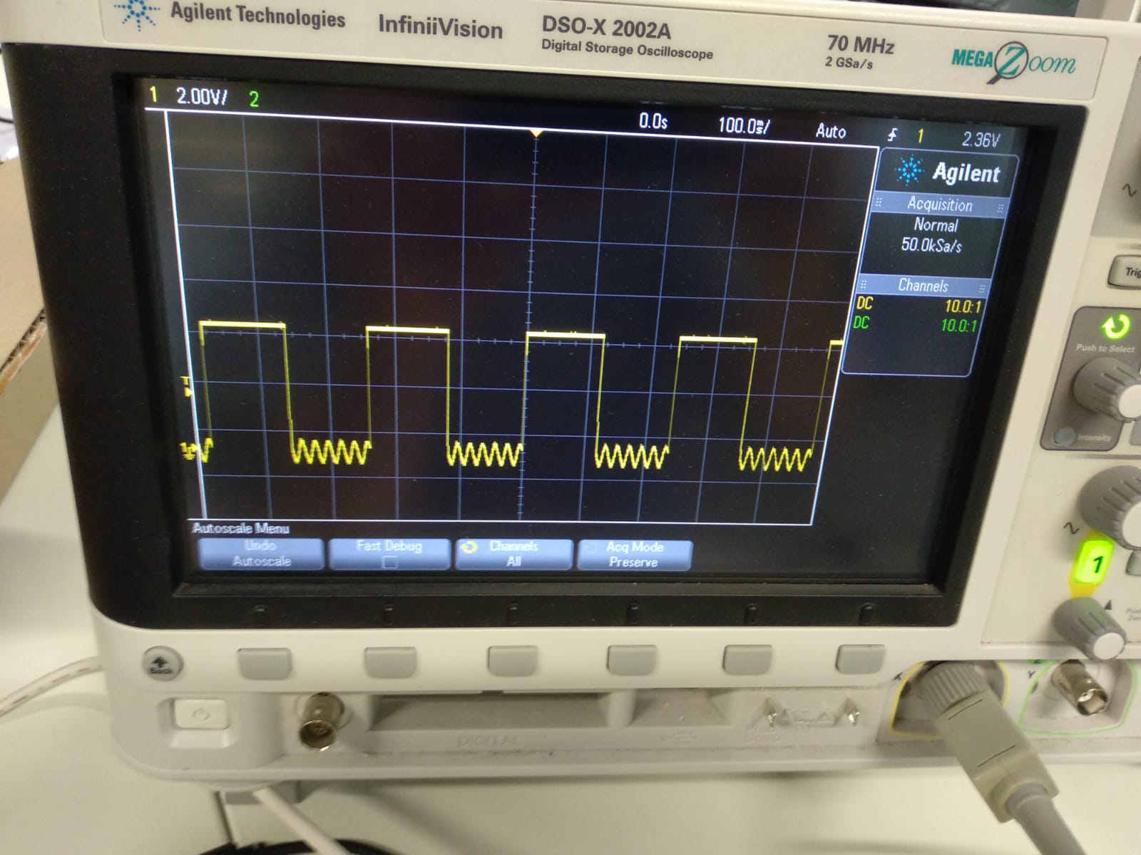
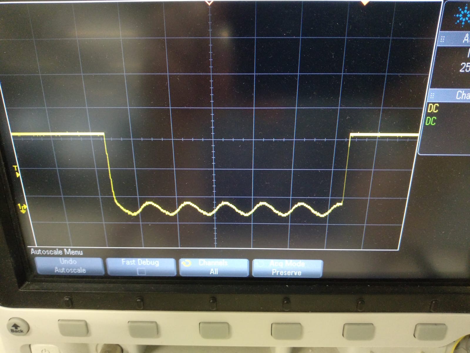
After connecting an oszilloscope I could take a look at the generated signal, showing a square wave with some base noise whenever the relay is cutting off the connection.