.png)
Hi! Welcome to Week 17
This week’s assignment was to design a machine that includes mechanism+actuation+automation, build the mechanical parts and operate it manually as a group.
This week’s assignment was to design a machine that includes mechanism+actuation+automation, build the mechanical parts and operate it manually as a group.
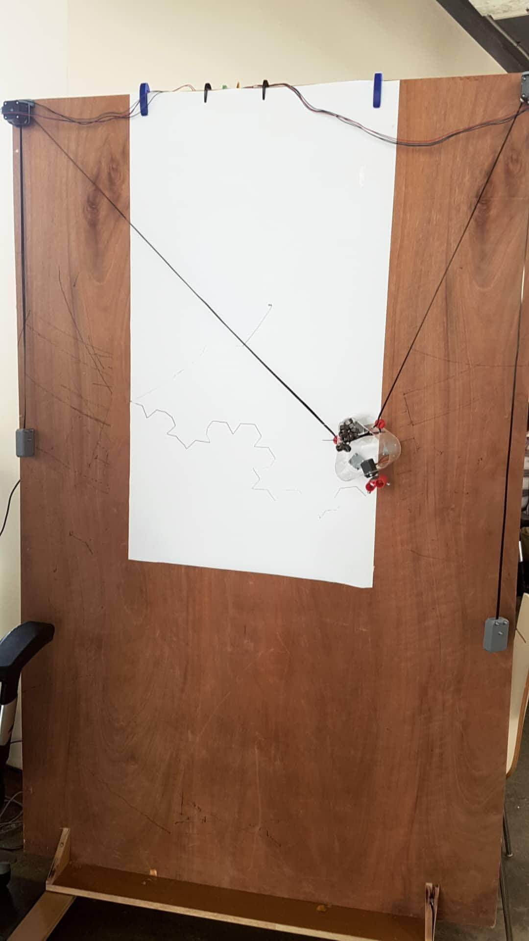
This week, my colleagues and I wanted to make something related to fabrication. After brainstorming, we decided to build a machine that can draw on the wall.
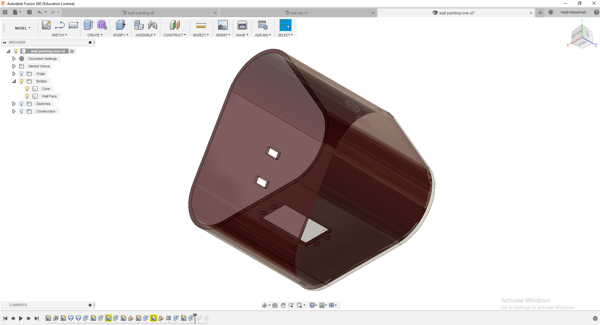
We divided the tasks between us and I had the task of designing the center piece that will hold the pins and servo motor.
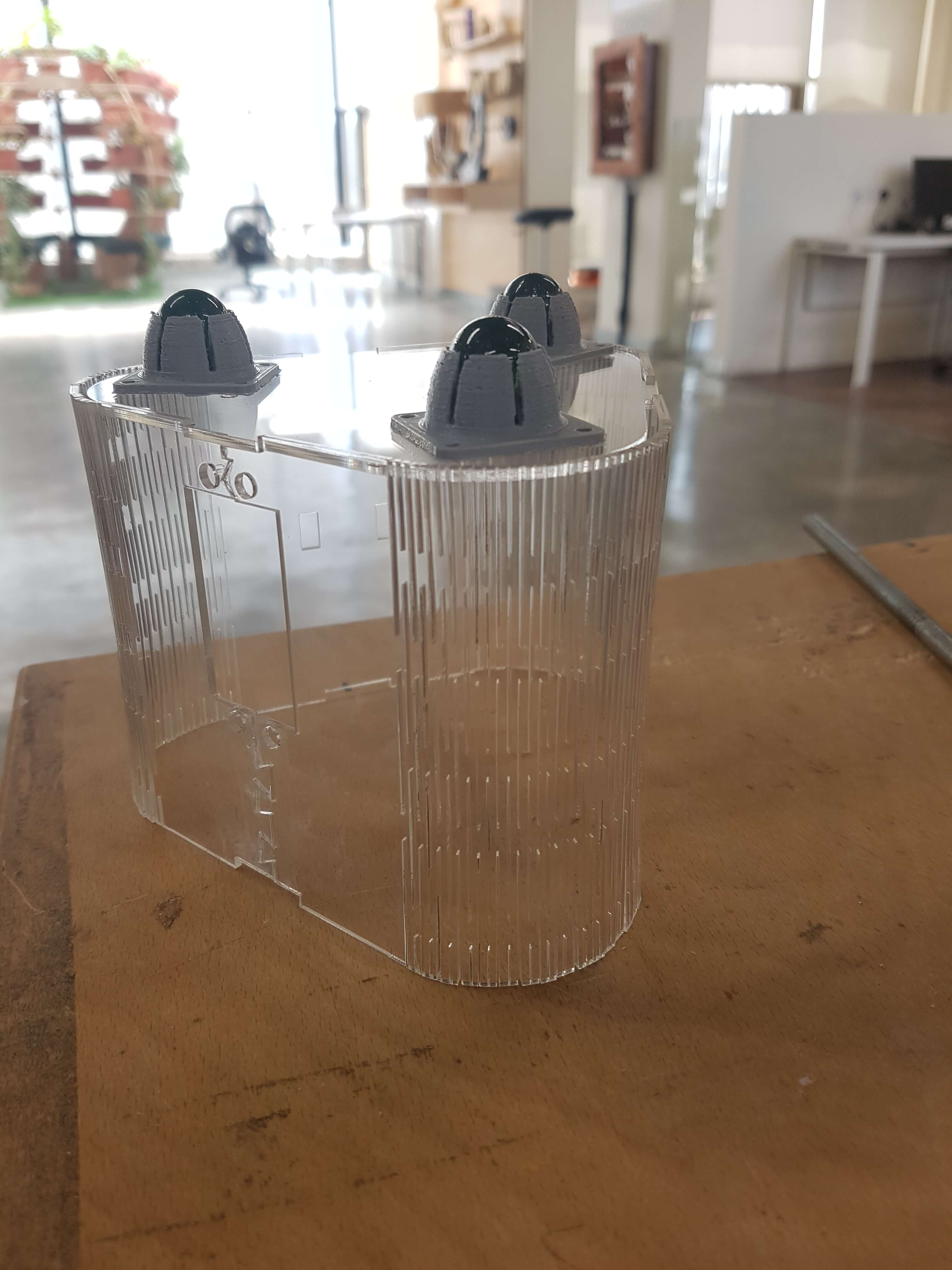
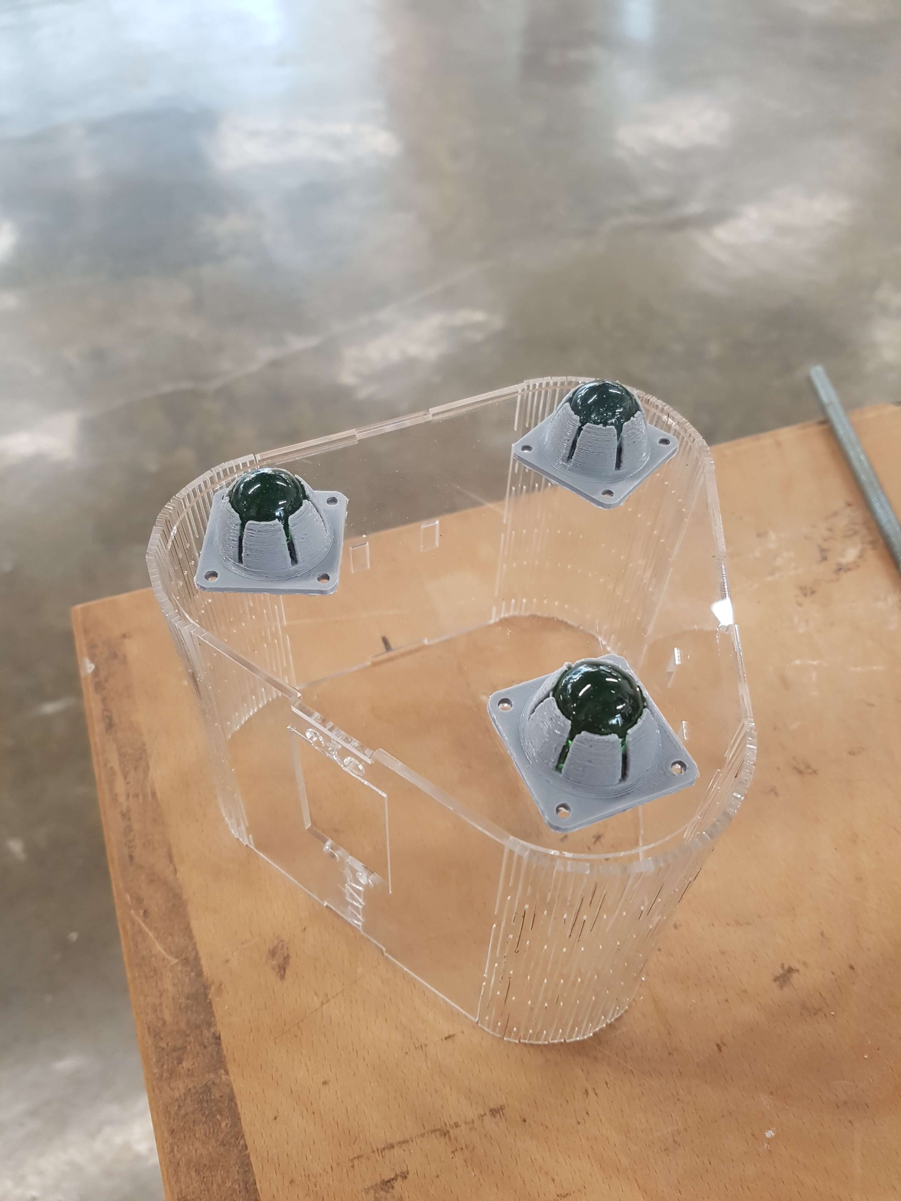
My colleague Tarek had already designed the marble balls holders, which will be used to make the piece's movement smoother against the wall, and my colleague Ahmad designed the pins' holder which will rotate to change pens.
I started my designing process by checking the machines available online for the same purposes. I tried to understand the components and arrangements, and the value of each component in the design. After I had a clearer understanding, I started sketching few possible designs:
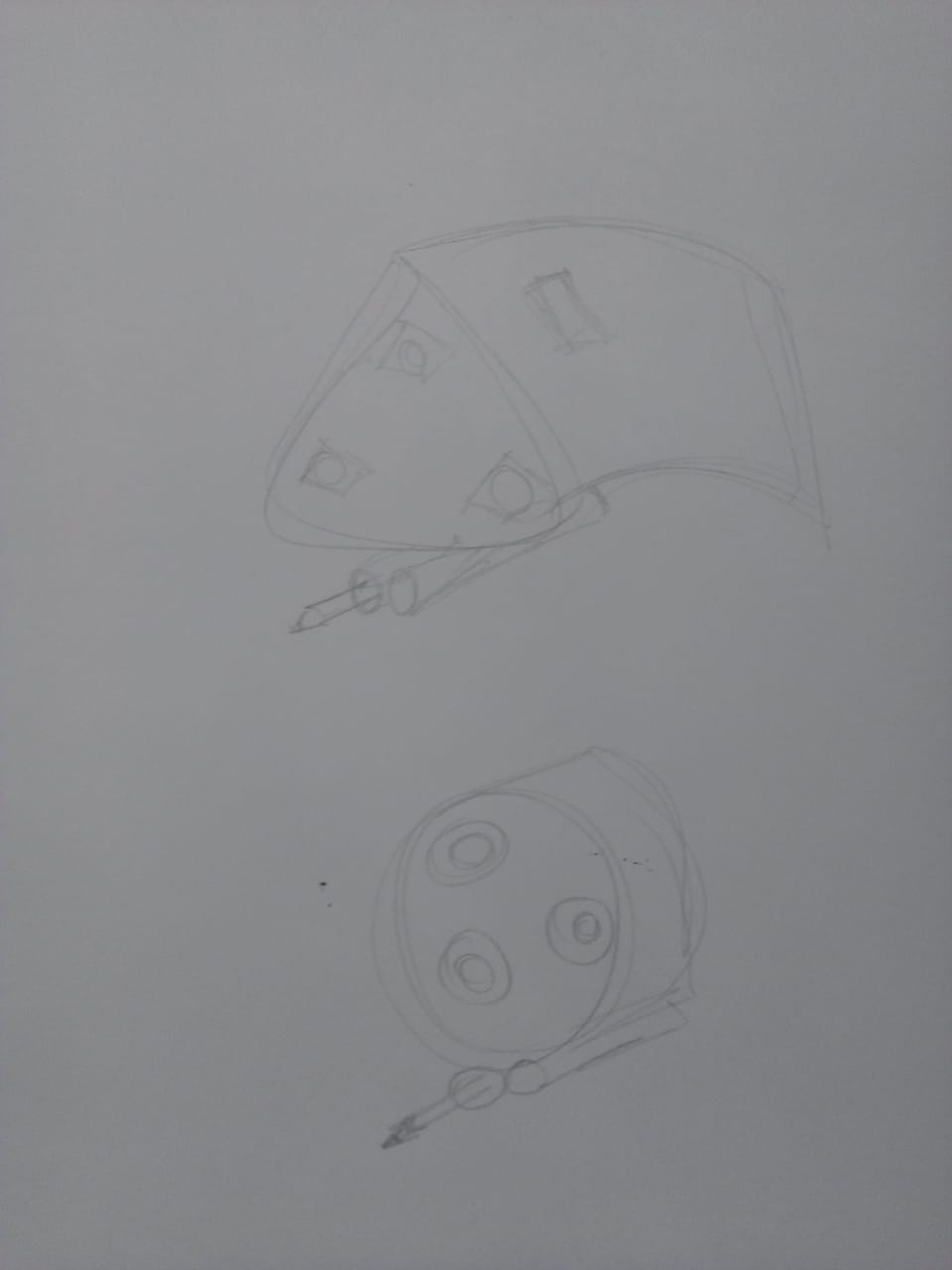
My colleauges and I discussed the pros and cons of each design, and we then settled on making the first one, but shortening it's depth to make more stable when moving.
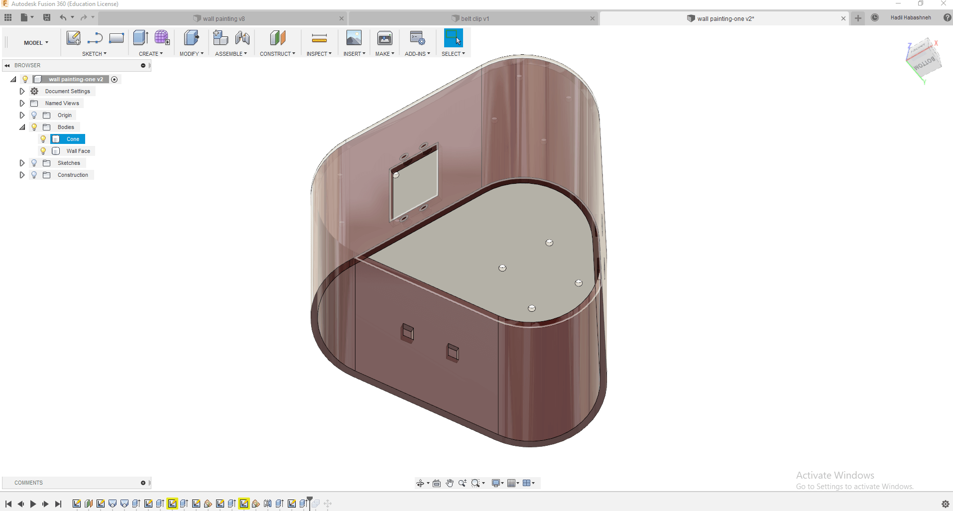
I moved to the designing process on Fusion360. The first design I made had few points that could have been enhanced for an optimum design, which are:
* Increasing the distance between the ball holders, placing them closer to the corners than the center.
* Cutting the depth of the machine to the smallest depth possible to take advantage of inertia.
so, what I did is I went back to the design, increased the distance between the ball holders, and made the size of the tail smaller, this is the final design
Now that it was ready and the whole team agreed to it, I made the 2D plans on CorelDraw, and then produced them using laser cutting.
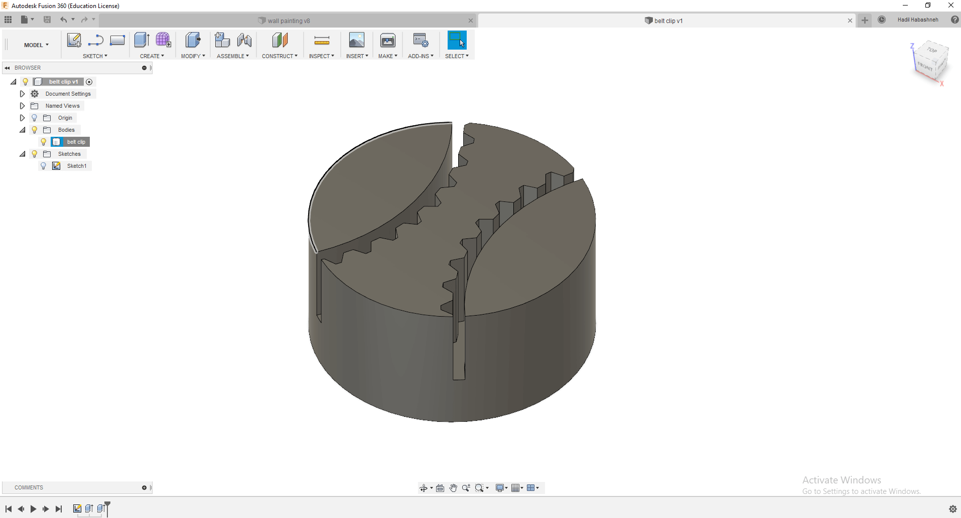
I then moved to designing another part, which is a clip to hold the belts in place around the center piece.designed the belt clips, again using fusion 360, it’s a simple design of a small cylinder with belt shaped cuts in it. This is how it looked:
And I 3d printed the pieces, and then tested them with the belt. It was a tight fit, which means it would hold the machine in place.
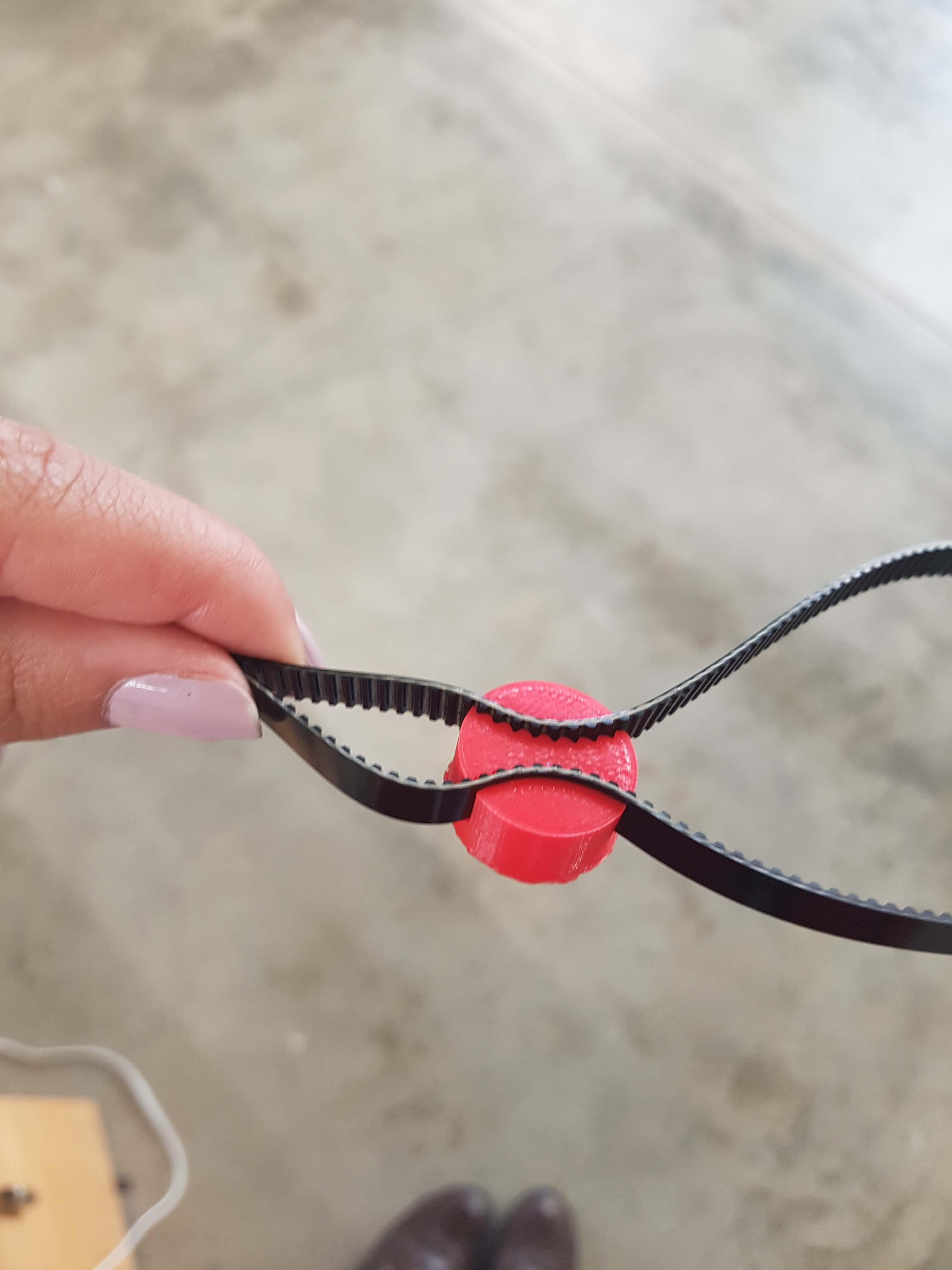
For the belt clips, they were a bit tight for the belts, but that turned out as positive characteristic as it gave better hold to the belt. I also assembled the marble ball holder to the face using screws.
Download the Body file.
Download the Clip-STL file.
Download the Clip-original file.
After the machine's mechanical parts were assembled, it was time for wiring, programming, caliprating then testing the machine.
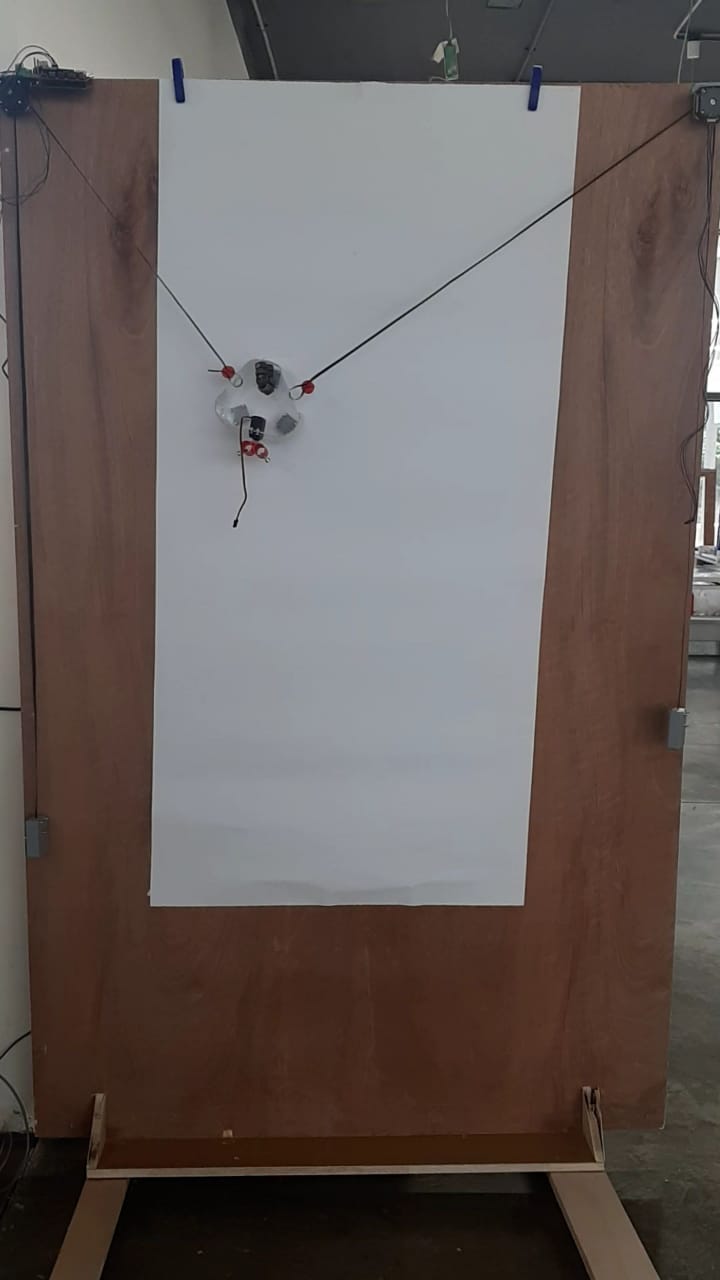
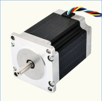
The movement of the machine depends on two stepper motors. We used a 6 wired hyprid steper motor.
The fact that its hybrid, makes connecting the common leads optional. So we connected the four important wires to a shield holding two drivers, one for each stepper motor.
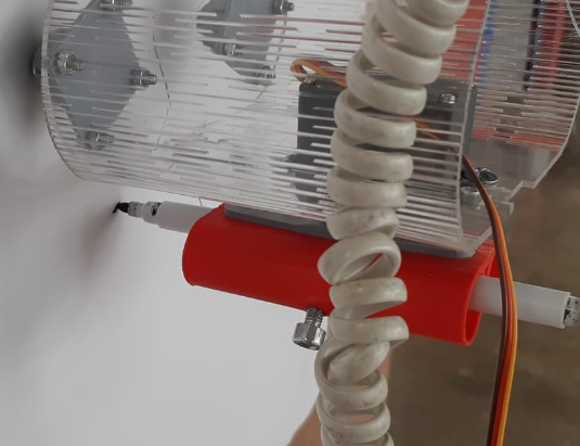
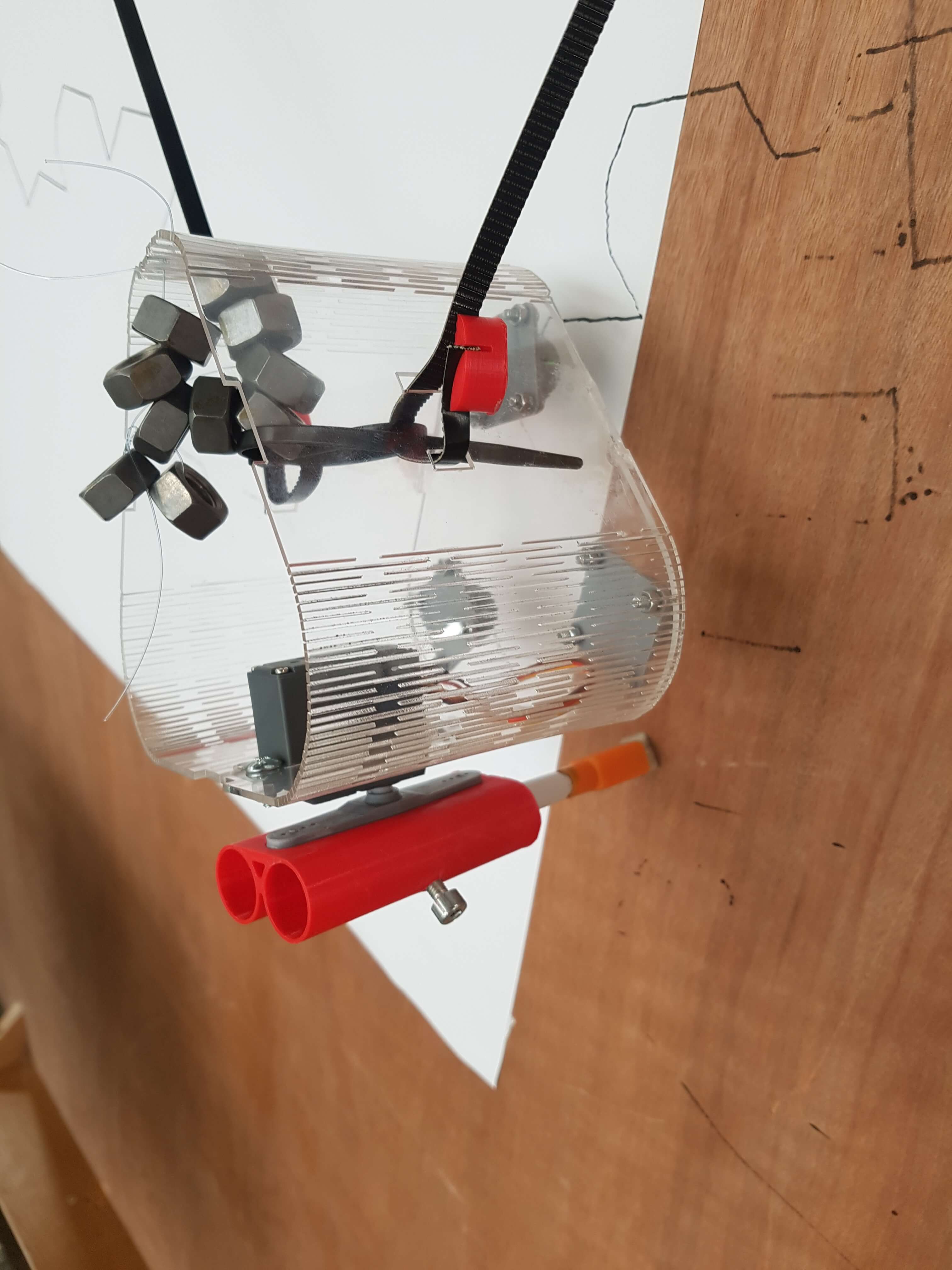
In this step I assembled some of the pieces together. For the main body, the pieces fit into each other, and to add more support to it I glued them together as well. On the same piece I added the servo motor and the pin holders, and fixed them to place using screws and bolts.
A problem here was that the body tilted towards the wall, to solve that, we added few bolts on the back to work as a weight to balance it.
I tried to use screw on the 3d printed arm that is placed between the pin holder and the servo, but the holes were too tight and it didn’t work, so instead I used glue.
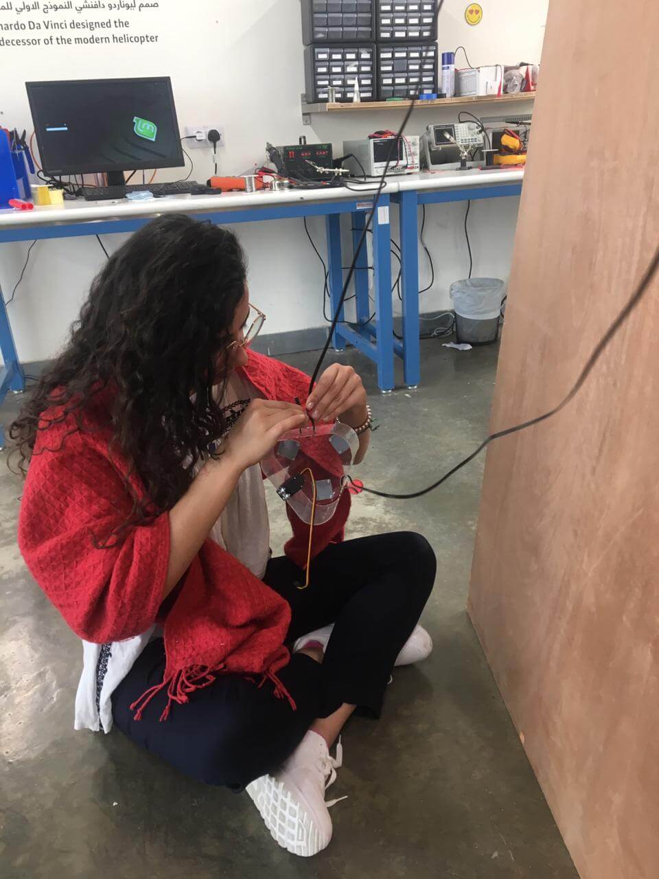
Then I helped with the wiring, before I worked on soldering the wires to pin headers in order to place them to the shield.
worked with my teammates on the wiring and soldering.
I then moved on to designing the case of the Arduino and shield. My first instinct was to use Fusion360 to design it since there are many holes and so to account for, but I then thought that it would be much easier, more accurate and faster to use an auto-generator instead, and then adding where I wanted the holes and other features to be using CorelDraw. I used MakerCase, which is an online software that generates plans for laser cut for customized boxes. I also made 2 handles for the box to keep it in placeon the wooden board.
I then used the laser cutter to cut the box, assembled it together and then placed the board, shield, and wires in place. I finally placed the box in between the 2 motor. You can download the case plans from
here.
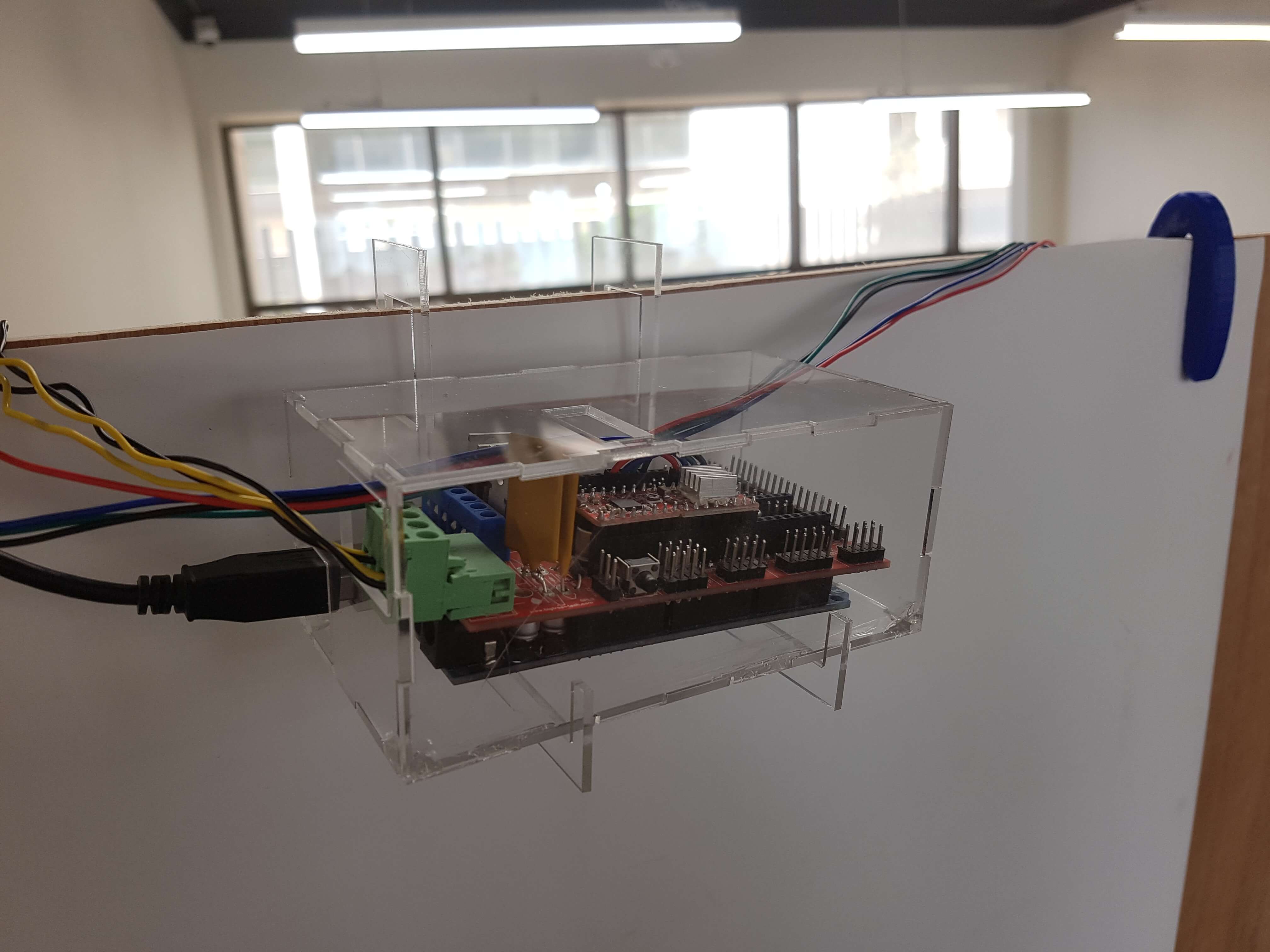
The servo was connected as well to the shield through a telephone cable, to make its movement easier without affecting the machine.
As we were working on tight schedule, we didn't have enough time to go through with our idea of having the servo change the pens, but we would like to keep working on it for later on. Also, I think that placing the pin in the middle of the part would be better for the machine, as when it's in the center, no tilting in the resulting drawing will appear.
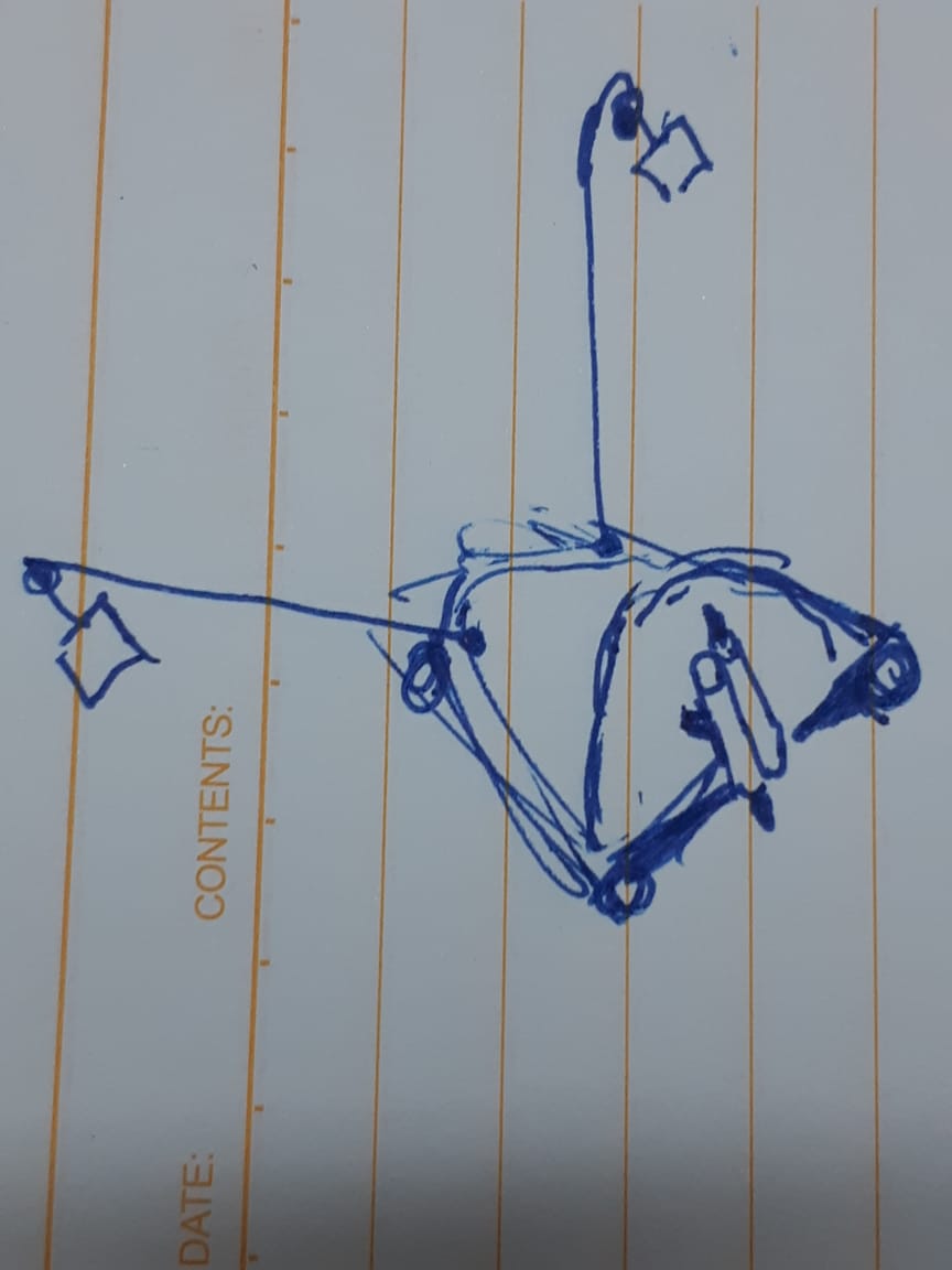
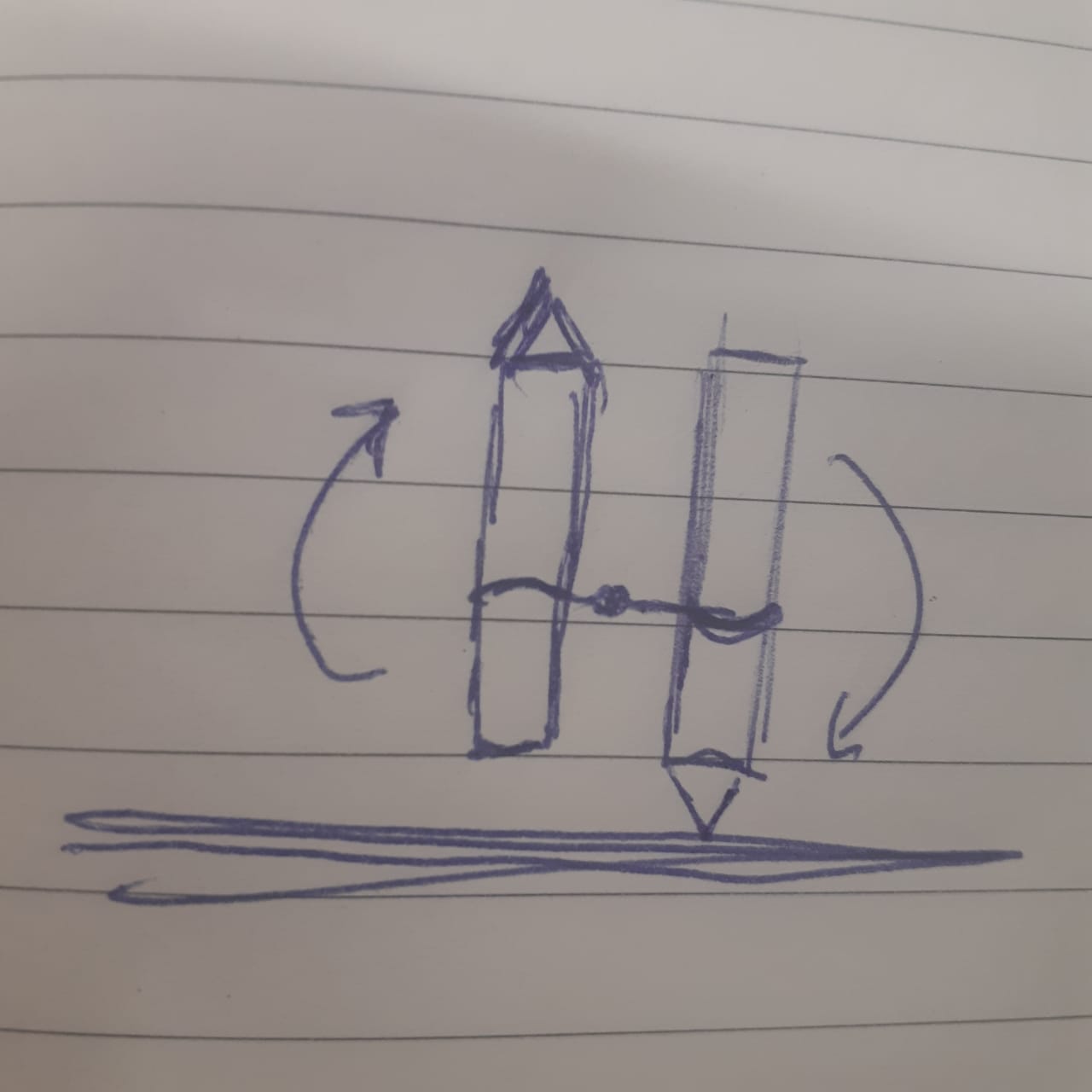
Here are the images of our machine:
And you can head to our team’s page to check the full documentation of the machine.