Week no.3
- Computer-Controlled Cutting
- Laser Cuter
- Vinyl Cuter
Assigments :
- Group assignment: make lasercutter test part(s), varying slot dimensions using parametric functions, testing your laser kerf & cutting settings
- Individual assignment:
- Cut something on the vinylcutter;
- design, make, and document a parametric press-fit construction kit, accounting for the lasercutter kerf, which can be assembled in multiple ways.
- Cut something on the vinylcutter;
- design, make, and document a parametric press-fit construction kit, accounting for the lasercutter kerf, which can be assembled in multiple ways.
CAD Toolkit
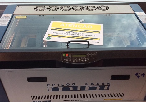
It was a bad start with a broken laser-cut machine in our lab !
The maintenance process can take a while since the replacement parts are in the middle of a importation process to Brasil.
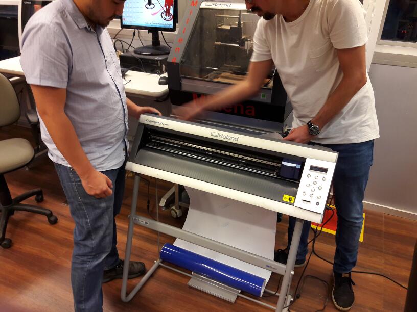
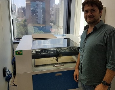
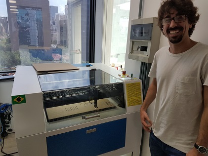
Meanwhile, we searched for alternatives with the others FabLabs in São Paulo and got a Help from Rhysos (LAB Educação) to use their machine, an ECNC L-560. Rhyzos is a makerspace for educational methods to K12, also trains teachers to work with maker education.
Group Assignment
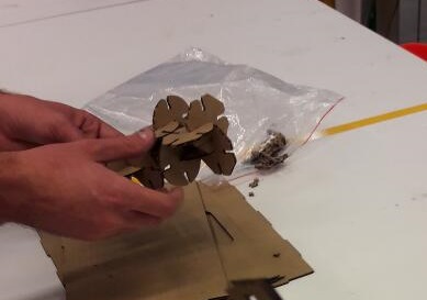
And so, me and my colleagues from Insper – Victor, Daniel, Fabio and our local Guru Kenzo – went to Rhyzos makerspace to prototype the press kit. More detail on our group work can be found looking through their project pages, I also referred some of their pictures as we were together at the testing.
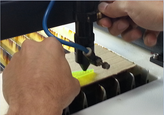
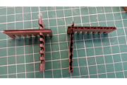
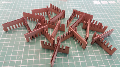
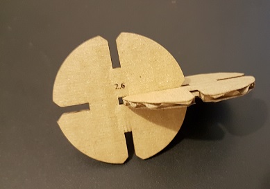
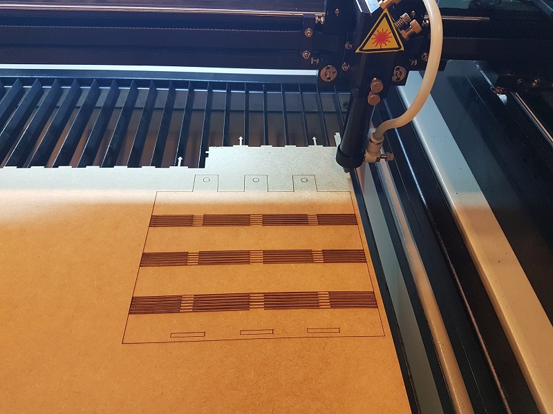
We managed to cut some cardboard parts and test joints and tolerances. The first problem was our cardboard - singlewave - 3,00 [mm] thickness from our inventory, we couldn´t find the ideal type, it happens that it was not stiff enough causing successive folds.
Even though, we learned their machine calibration, test some cutting parameters, cardboard orientation, tolerances, kerf design to reduce the bending problem. I took the test part that had the best fit (in my opinion), redraw and made it parametric so that can be used scalable and uncommitted to the cardboard width.
We learned from kerf test by varying the width of the cut joint from 2.6 to 5.1mm and combining them. To a sheet of 3mm the best match was with an interference of 0.2mm.
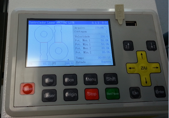
About the machine, there are no magical values, I recommend always test before producing a part in the laser cut. The power and speed configurations depends on material and thickness and vary from machine to another but also the calibration and condition of the CO2 tube. And of course, always calibrate the laser focus before use with the proper standard piece (photo).
Individual Assignment – Parametric press-fit
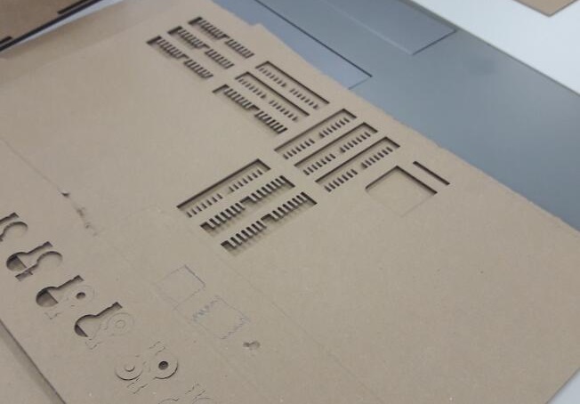
The next version came with parametric modeling, the Press-fit drawing was converted to a full parametric model. And so it received restrictions, relations, variables and functions becoming a mathematical function drawing.
Actually the drawing does not have a single absolute measurement, the dimensions are all related to a constant of Thickness and its functions. For example, the kerf is 0.2mm smaller than the thickness of the sheet and has a chamfer of 45º with twice the thickness size to allow an appropriate fit.
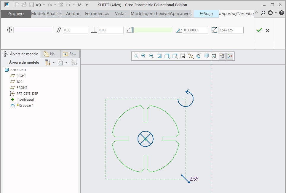
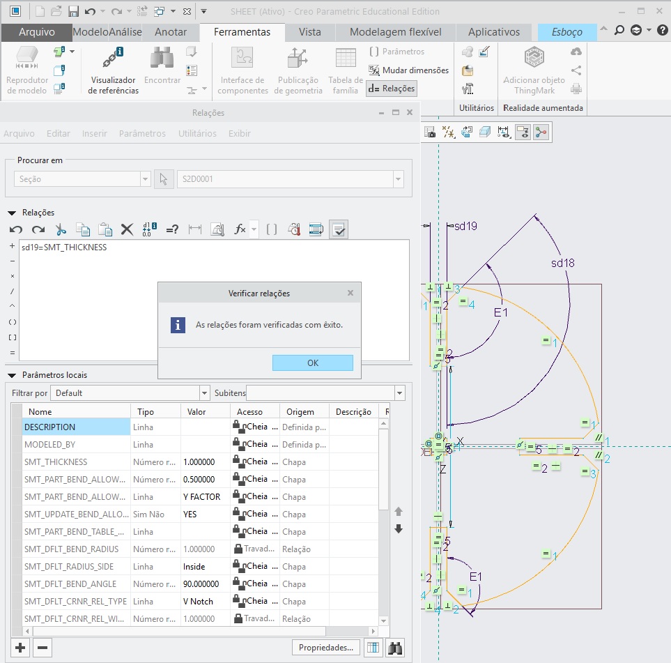
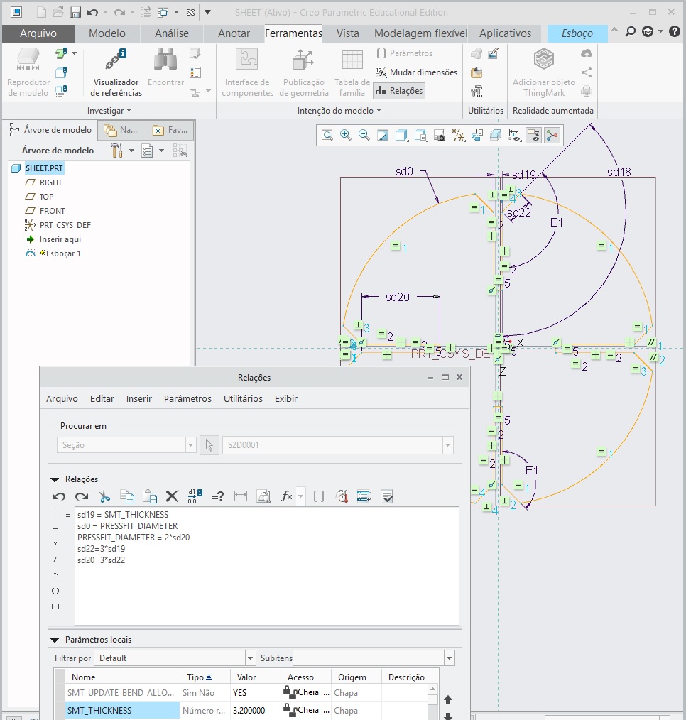
In CREO, at the sketch use TOOLS>FLIP DIMENTIONS to show the hidden variables. Then, by adding TOOLS>RELATIONS it opens the toolbox to make the parametric equations. In this case I create a NEW MODEL>SHEETMETAL template that is prepared to work with metal sheets and comes with global variables of SMT_THICKNESS associated.
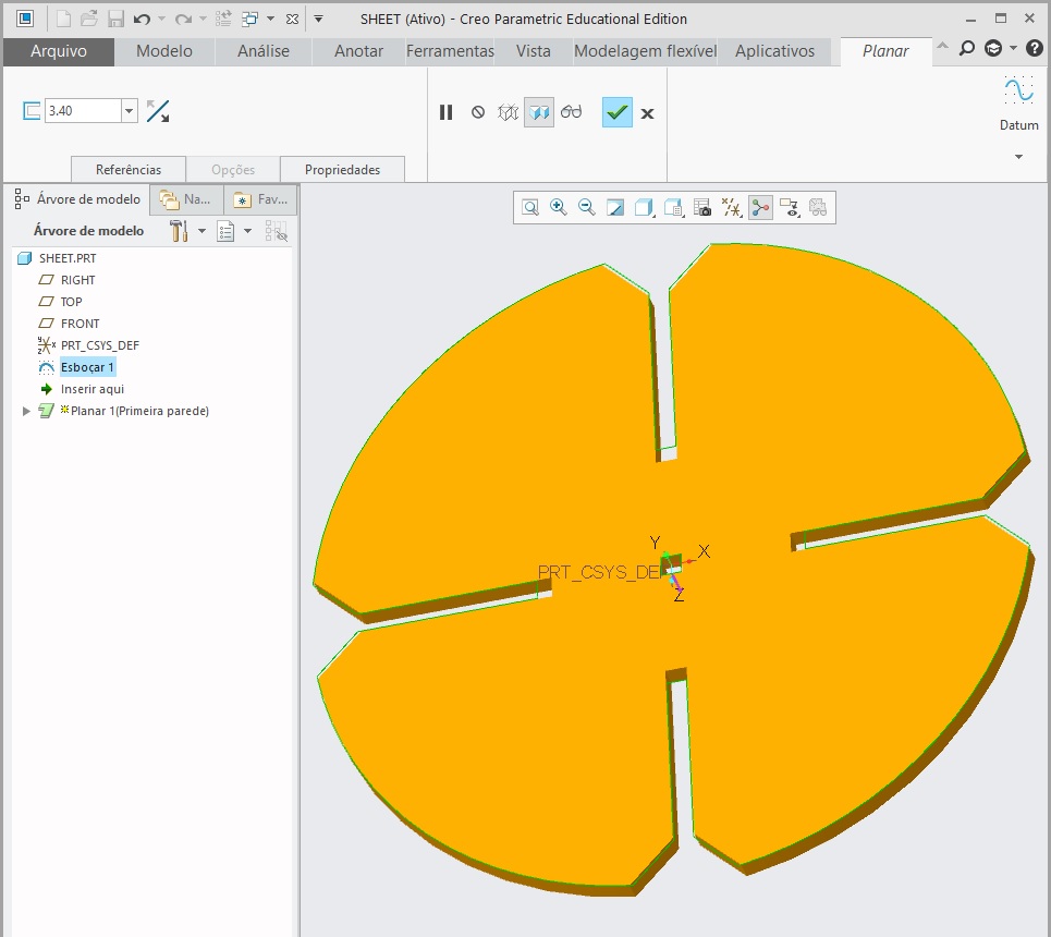
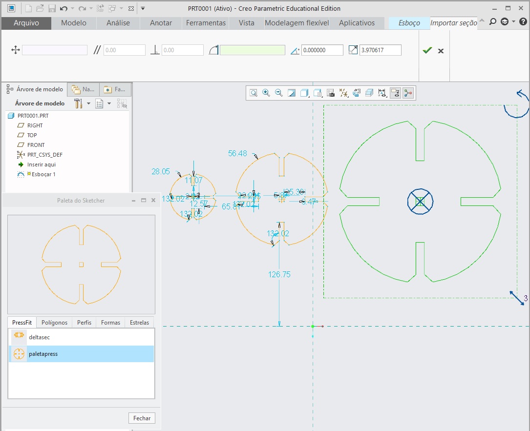
Once you have saved the sketch file (.SEC) in the working directory, the software automatically recognizes it as a palette. You can then easily import the profile to any other project or create a pattern with many copies of it in any scale you want (last picture).
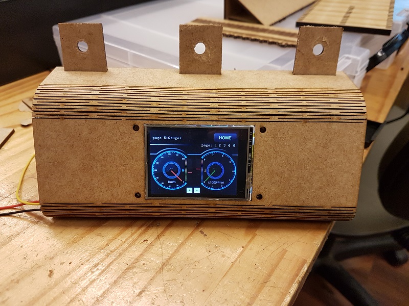
Flexible Wood - Parametric
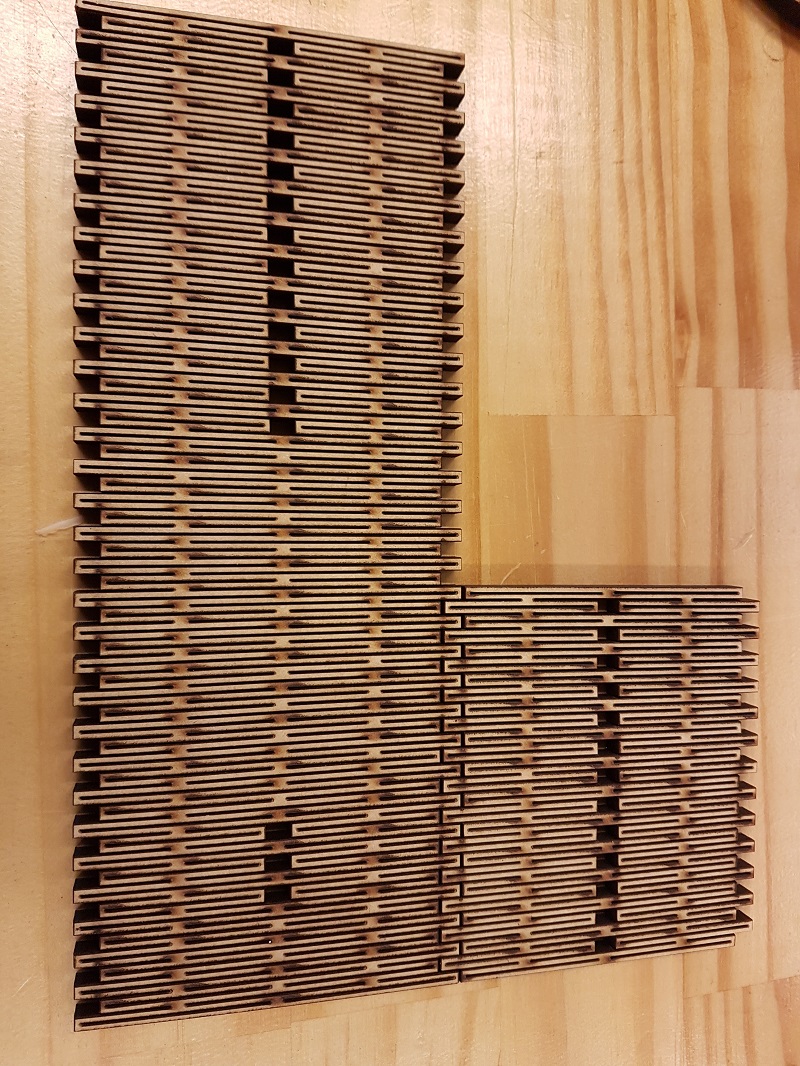
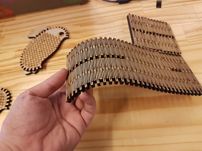
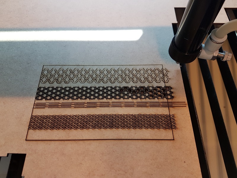
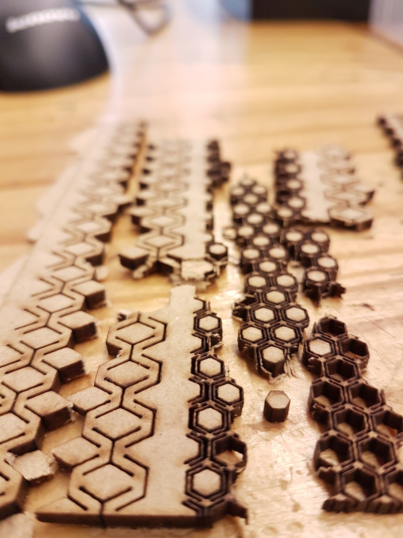
I wanted to make flexible wood and build a case. So I made some pattern tests with the laser cutter to find the dimensions that could make it flexible by just looking at internet pictures.
I found a relation that could work, the distance between cuts were 1.2mm for a sheet of 3mm thick plywood R=0,375. Also tried different and more complex patterns, but they had a very limited flexibility so I stuck to the most reliable that was the straight line cut.
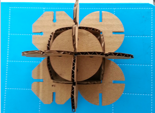
So I created a pattern in a sketch on Creo Parametrics that could be easily imported to the drawing as a cosmetic feature. The height of the pattern ca be then adjusted to the wood thickness. Also tested it in a more advanced parametrics, by using sheet metal design I could bent and shape the box. Once imported the recorded pattern I opened the drawing relations and linked the cosmetic height to the relation of 0,375 of the variable Thickness. The practical result is that I can scale the box and change the thickness of the sheet so the drawing automatically regenerates.
To better understand the mechanics of parametric modeling I recommend watching the online video tutorials from PTC – Learning Exchange and a lot of practice.
Individual Assignment – Vinyl Cut

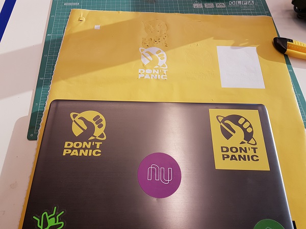
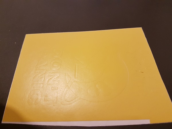
For this task I choose to cut a “Don´t Panic” Fan Art – reference from Douglas Adams book “The hitchhiker's guide to the galaxy”. Witch by the way, is a convenient slogan for every FabAcademy student who has late documentation to do !
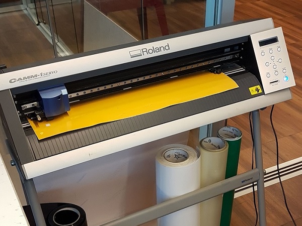
The process was pretty simple and straightforward, since the vinyl cutter works like any paper printer. Just downloaded the Roland GX-24 drivers and I was good to go!
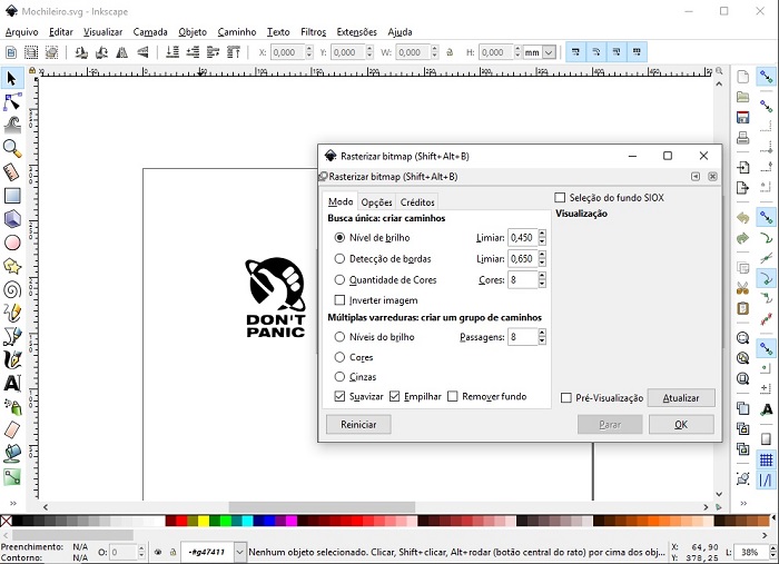
The only other tool I used was the software Inkscape (photo) to clean up and vectorize the image and then save it as pdf. One good reference is their online tutorial and videos for tracing bitmaps.

By changing brightness and edge detection the results can vary (a lot) as well as you job to clean up. Another hint that helped me was to paint (fill up) areas as the cutter detects border and cut outside.
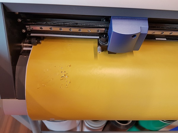
On the machine side, one thing to do is adjust the cut-force. It´s a small calibration but the only way to do it is testing yourself. The cut-force depends on the width of the vinyl you are using, so print a small version and try it out ! Another thing, always remember to check the conditions of blade for a clean cut.
The result was as an awesome stick! So that I ended up using both sides (positive and negative) of the cut, you can see by the pictures. Just one last hint: to proper unstick the positive part without messing up, I recommend using a piece of transparent contact stick, helps a lot not to lose the alignment – credits here for the instructables tutorial !