"Our technologies have outpaced our ability, as a society, to understand them. Now we need to catch up." - Joi Ito
Computer-Controlled Machining
This week I finally arrived to Madrid!
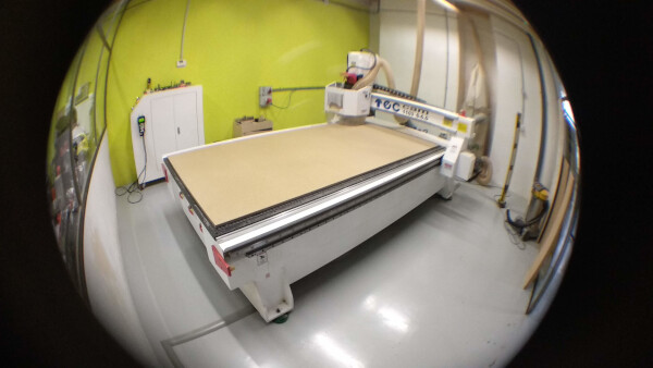
The Machine
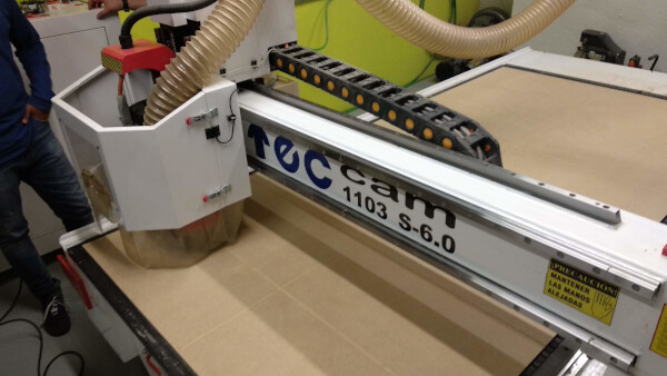
This week we learned to use the CNC Router. The one we have in Fab Lab IED Madrid is a Tec Cam 1103 S-6.0, part of the 1000 series.
Specifications for the assignment:
- Work area of the machine: 2400 x 1220 mm
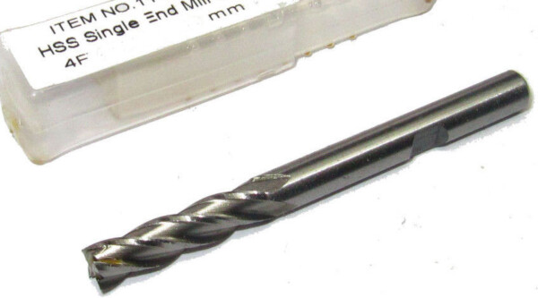
- Cutting tool used: 6mm diameter endmill
- Material: 10mm MDF
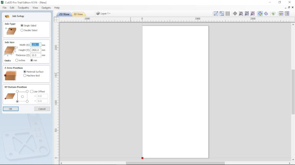
- Software of the machine: Cut 2D Pro
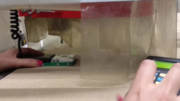
For calibrating the machine we used a Z probe to have the Z axis exactly over the material.
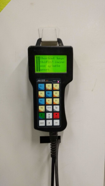
This machine uses a extended control, which I find very handy for moving around the machine for the setup. Also the room where the machine is, have a system that when you get close to the machine when is cutting it automatically stops for safety issues.
Designing the tests
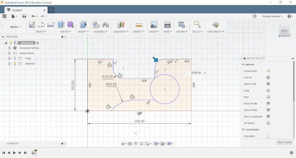
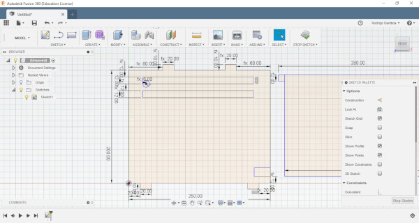
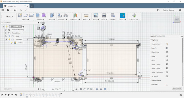
I wanted to make a little test for a mobile part design, first to get over the fear of using sucha a big machine and to understand how is the output material of the machine and the tolerances. I made the design using Autodesk Fusion 360.
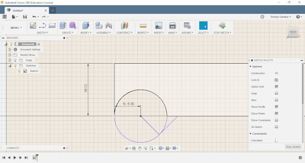
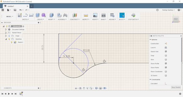
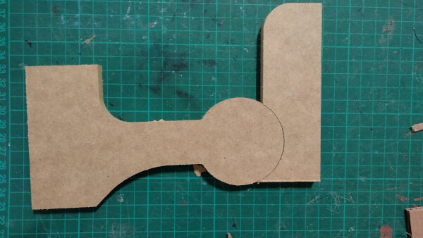
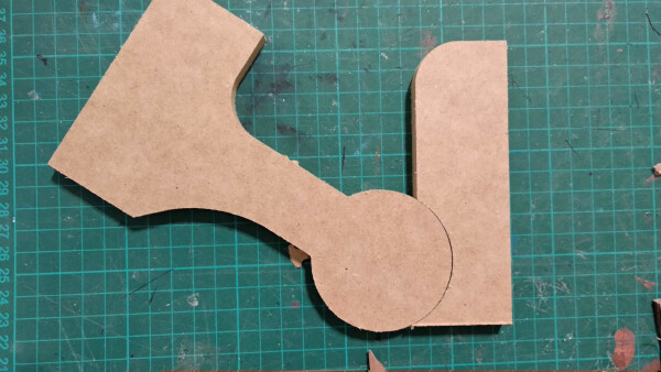
I first designed a mobile joint to see the mechanical properties of the material and if the friction affects it.
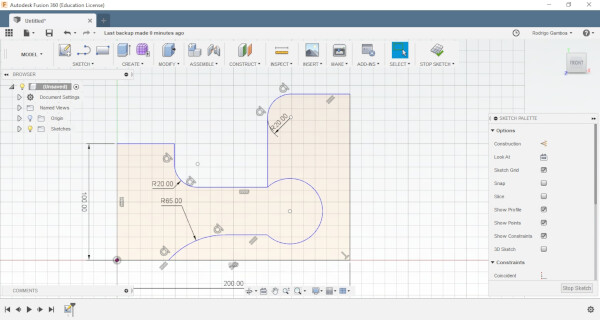
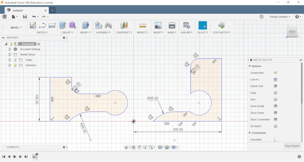
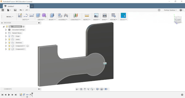
I then extruded the material to visualize better the results.
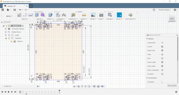
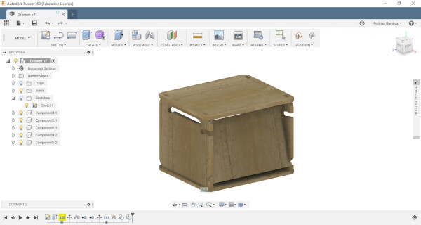
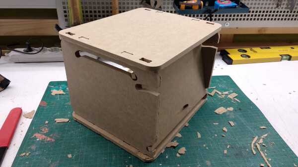
For the piece of this assignment I wanted to create a gift for a friend of mine. So I designed a drawer with a hidden door. This design has grooves at both sides so the door can slides into it. This design can be stackable.
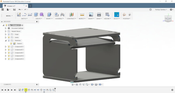
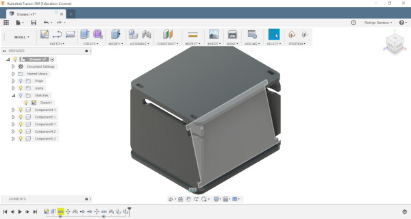
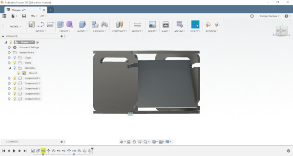
I applied some wood material to see how the final design would look like.
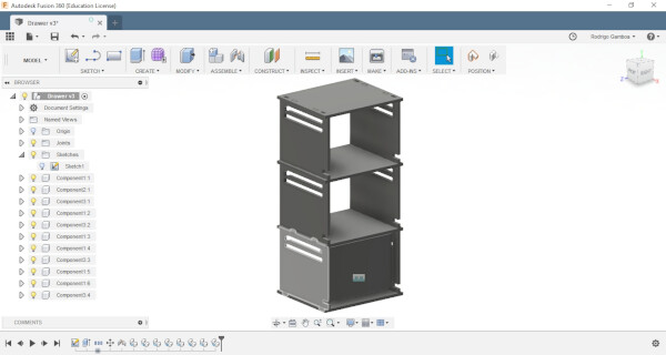
This is how the stackable modules could look like.
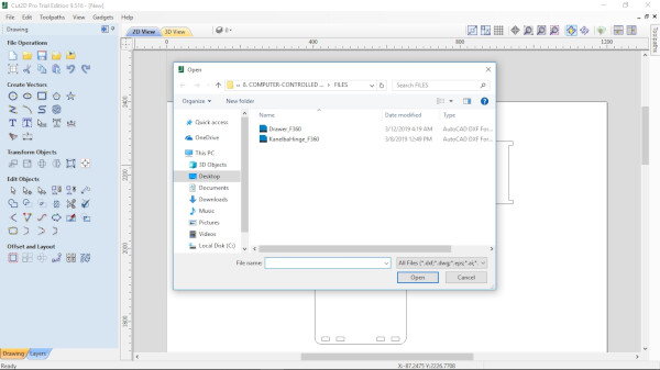
I exported both files as .dxf.
Preparing the tests files
For the machine we used Cut 2D Pro software to get the files ready.
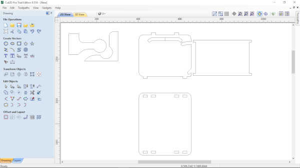
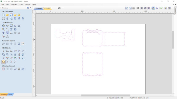
First I imported the two .dxf files.
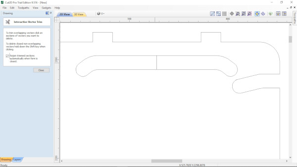
To fix some of the vectors, I used the Interactive Trim tool.
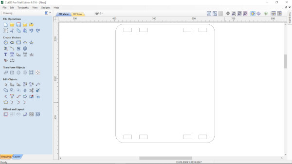
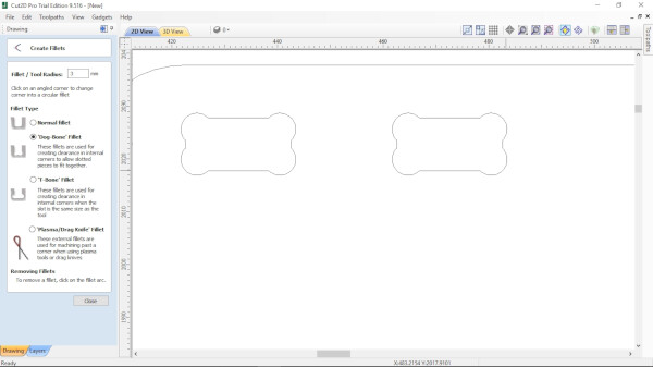
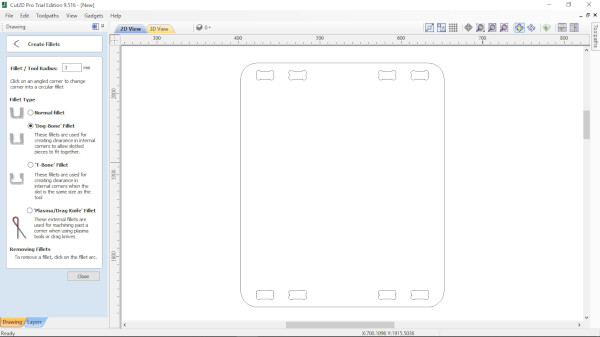
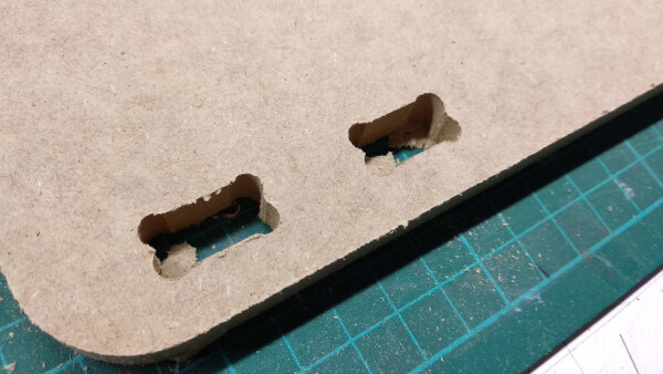
To improve the square joints I used Dog-Bone Fillet option, under the Fillet tool.
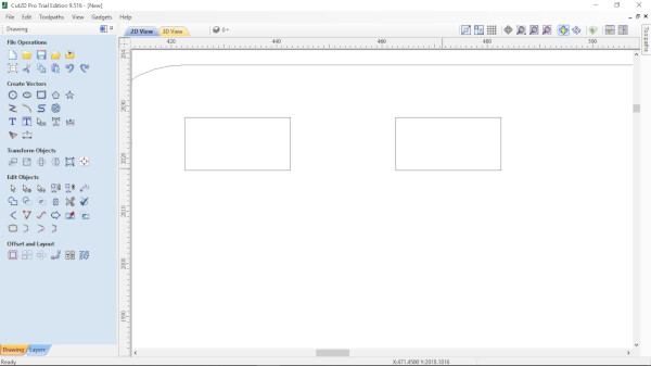

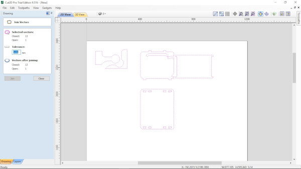
I then selected all the vectors and used the Join tool to close the open ones.
As a tool I selected the 6mm end mill cutter diamater tool, that is the one that we are going to use.
Feeds and speeds:
- Spindle Speed: 12000 rpm
- Feed Rate: 4500 mm/min
- Plunge Rate: 1200 mm/min
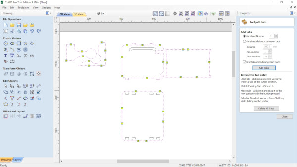
Then I selected the exterior vectors and choose the 2D Profile Toolpath tool, under the Toolpaths tab, at the top right corner. I used the Outside option on the Machine Vectors tool. I then added some tabs to fix the pieces while the machining work is cutting.
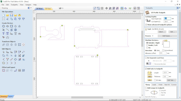
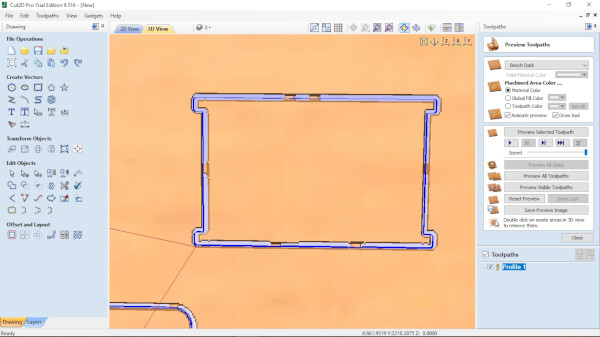
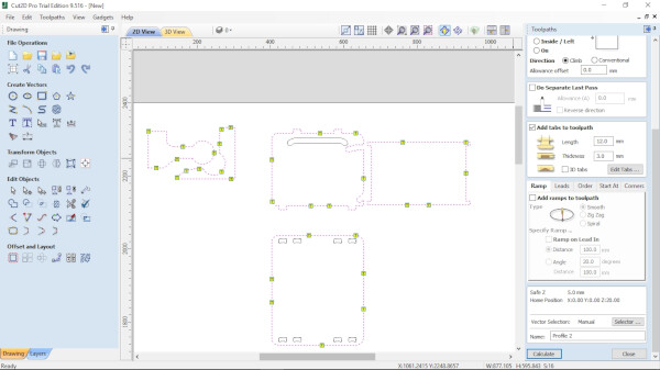
I then created another Profile, this time using the Inside option on the Machine Vectors tool.
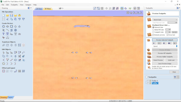
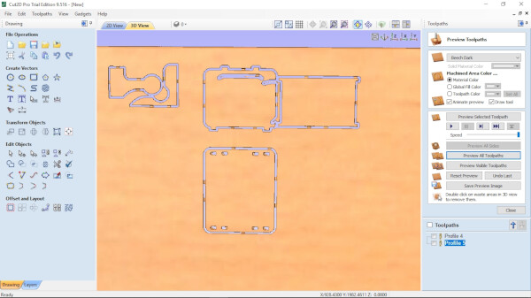
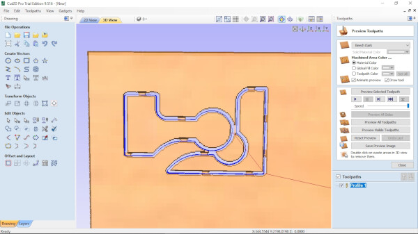
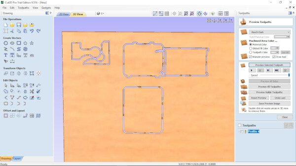
After simulating the cutting and seeing everything looked fine, I exported the Toolpaths as a .tap file.
Fabricating the tests
I then sent the cutting file to the machine with help from the Fab Lab staff.
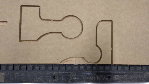
I recorded a timelapse of the machine milling.
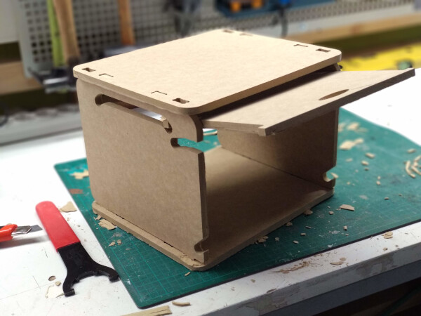
I wanted to paint the drawer using different colors for each piece but I didn't have time.
Files
- Kanelba Hinge .f3d (Fusion 360)
- Kanelba Hinge file .dxf
- Drawer with hidden door .f3d (Fusion 360)
- Drawer with hidden door .dxf
Group Assignment
To see this weeks group assignment click here.