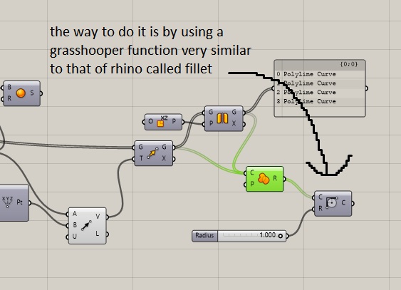
basic pressfit processs
see kerf test later.
3mm cardboard is used and in this case a 0.2 mm kerf is added
.jpg)
.jpg)
.jpg)
.jpg)
.jpg)
.jpg)
.jpg)
.jpg)
.jpg)
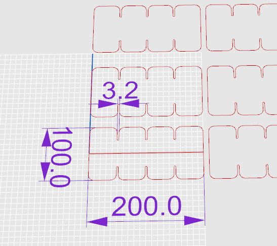
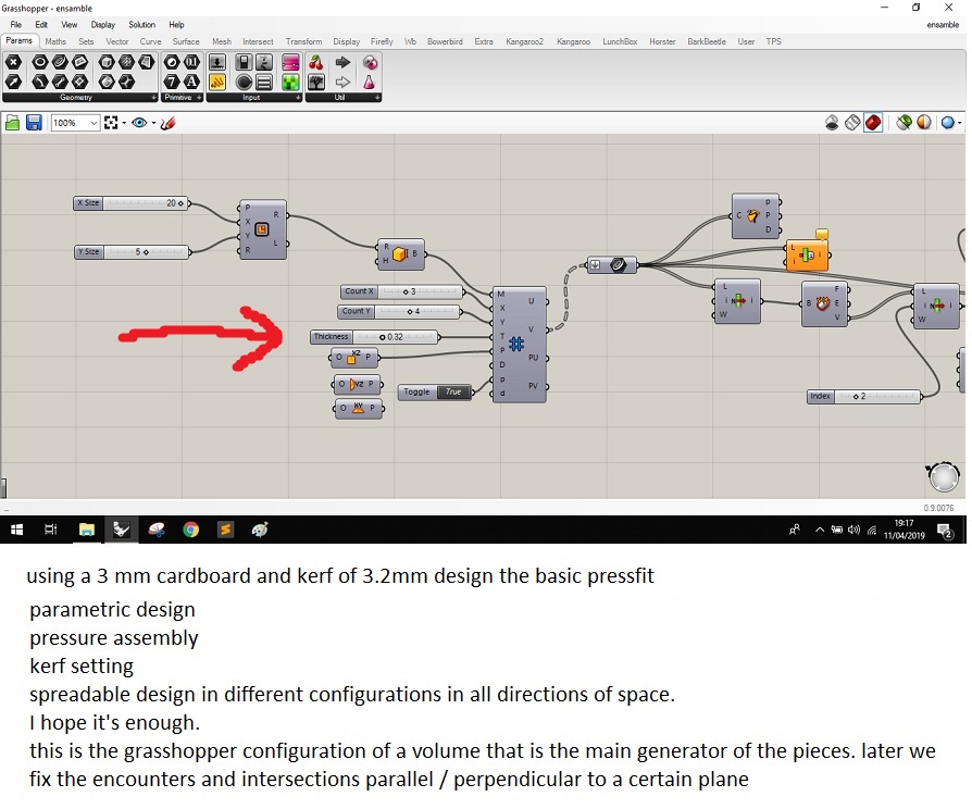
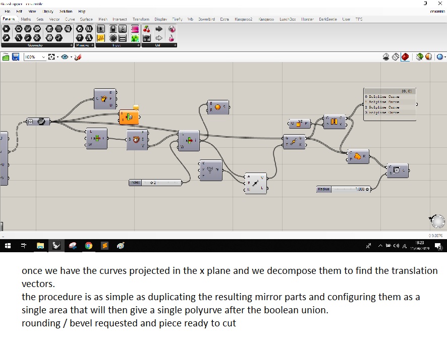
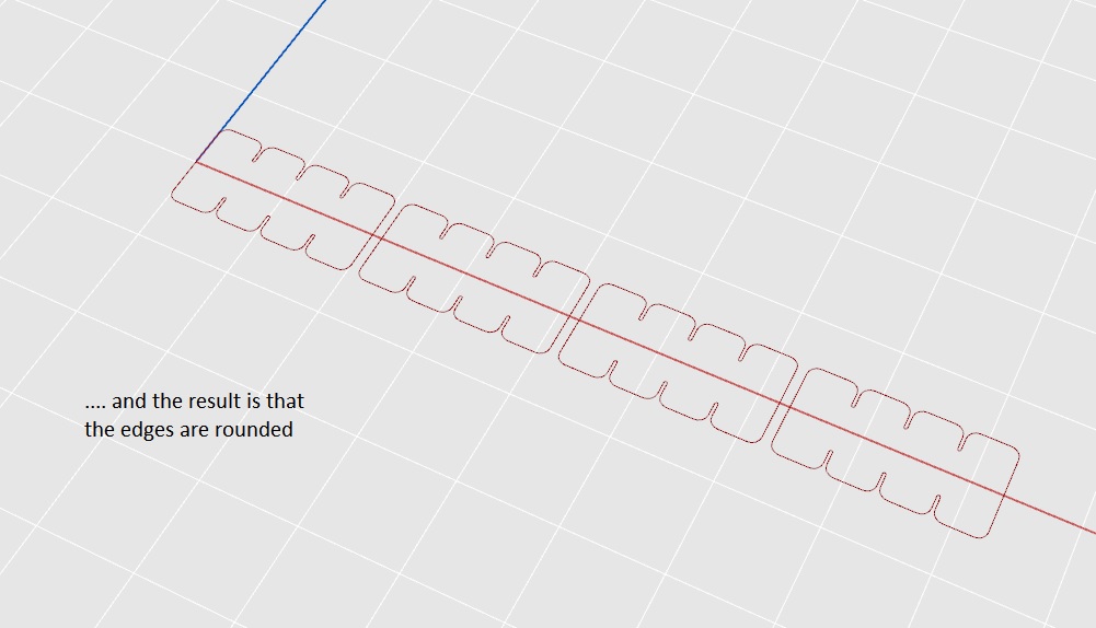
press fit parametric process
generating a waffle for the spatial construction of a figure with volume by flat pieces
As indicated in the fab academy assessment guide I approached with a model close to a possible final project
.JPG)
.png)
.png)
.png)
.png)
.png)
.png)
.JPG)
.JPG)
lasser cutting
Characterize your lasercutter, making lasercutter test part(s), making test part(s) that vary cutting settings and dimensions.
first I try the spirit gls
láser font 30 a 100 W (10,6 μm) / 20 & 60 W (9,3 μm)
work Área 810 x 610 mm ( 965 x 610 mm)
max size 1.016 x ∞ x 177 mm
table 1.025 x 705 mm
engine speed 2.032 mm / seg
Resolution (DPI) 125,
250, 300, 380, 500, 600, 760, 1.000, 1.500
Lens focal 2”, plus 1,5”- 4”
Vol 220V AC
Memory 32 MB stándar
Seafe Clase III
Pw 2.000 W - 4.400 W
there is two basic ways to use the lasercut : RASTER ENGRAVING and VECTOR CUTTING
UPDATE : engraving and cutting parameters
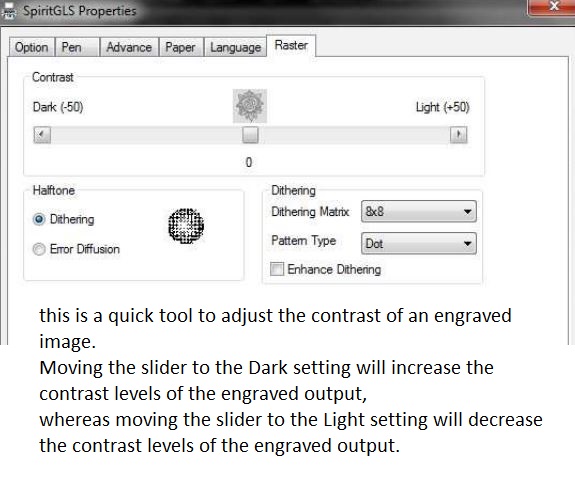
There is possible too adjust the power / speed settings or simply adjust the contrast of the image in software
DITHERING : This option controls the way a raster-engraved image is processed. The “digital image to engraved output” process can be processed via two methods: Dithering or Error Diffusion. Each offer additional output options yielding different output effects, style, and quality.
UPDATE vector cutting
most common for cutting and build
in the spirit you will need to set your design fill color to white and set its outline thickness between 0.001" (0.025mm) to 0.004" (0.1mm)
suggested parameters:
..for acrylic and wood power 100% and speed 30%
.. general parameters recomended using in fab for cardboard
..cutting : power 50% ( cut) // speed 30%
..mark and bend : power 30%// speed 90%
..engraving : power 20% // speed 30%
RECOMENDED MATERIALS
Plywood/Composite woods wood, MDF , Acrylic,Lucite,Plexiglas,PMMA Paper,carton Cardboard, Cork Polyimide Mylar Depron foam Teflon natural fibers : Cloth,felt,hemp,cotton Leather, NON-CHLORINE-containing rubber
NOT RECOMENDED MATERIALS:
PVC (Poly Vinyl Chloride),vinyl,pleather,artificial leather,PolyStyrene Foam,Fiberglass, ,Polycarbonate/Lexan, ABS,PolyPropylene Foam, HDPE,Carbon Fiber
process (testing)
.jpg)
.jpg)
.jpg)
.jpg)
.jpg)
.jpg)
.jpg)
.jpg)
.jpg)
.jpg)
.jpg)
.jpg)
UPDATE : kerf testing
for the kerf check I make a simple test figure with 3 mm cardboard.
so I consider an initial slot with 0.3 mm kerf, 3mm - 2 x (0.3mm) = 2.4mm
however due to the considerations of the material, due to its flexibility and the possibility of crushing in the joints experiment with a slightly larger dimension
.jpg)
.jpg)
The result in the fit of the pieces is to confirm the discomfort and sometimes impossible to fit when there is no kerf, despite the flexibility of the material.
KERF of 0.1 mm the fit is still costly facilitated by the flexibility of the material
and very inefficient in the assembly of small parts, or when the sections are very abundant.
KERF of 0.3 mm the behavior is perfect, allowing, with some slackness, an easy assembly in small and very abundant pieces
KERF of 0.5 mm is
excessive and produces excesive movement in the parts after being assembled.
.jpg)
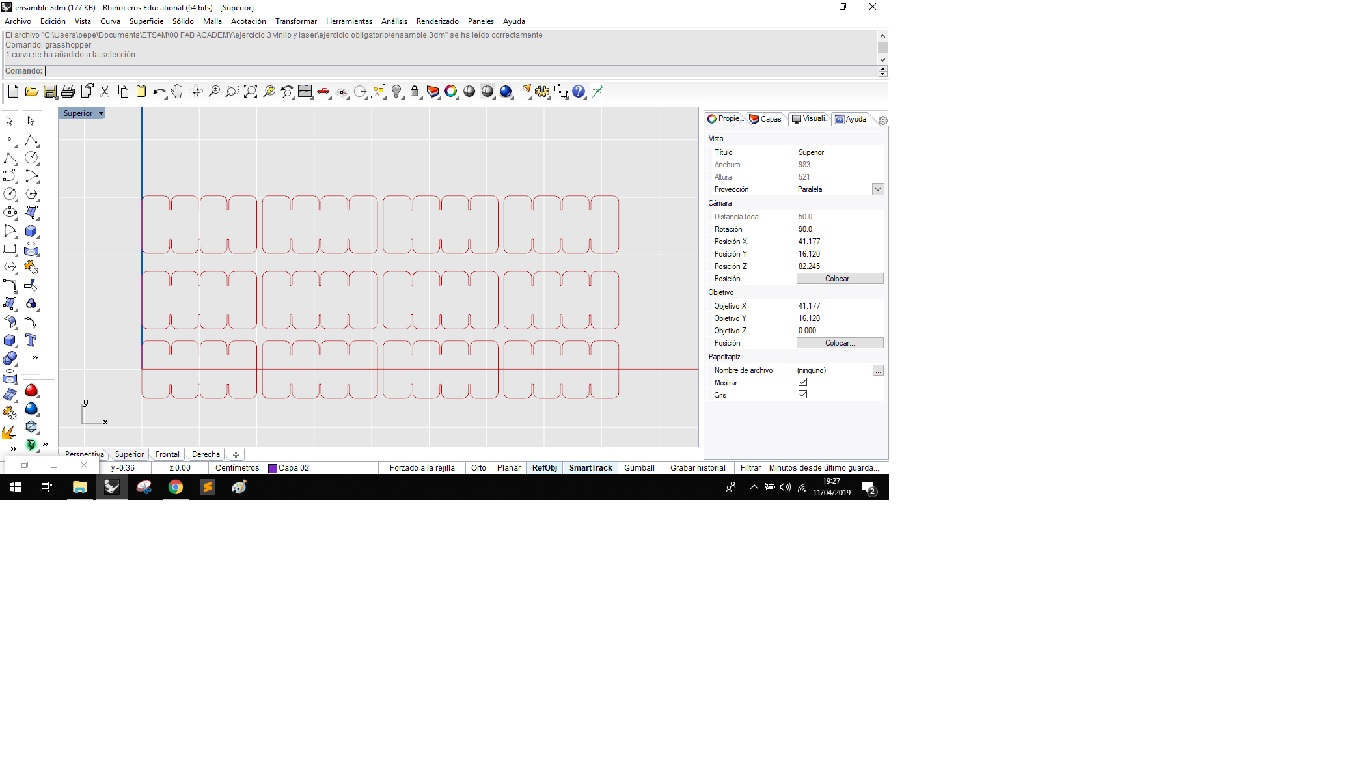
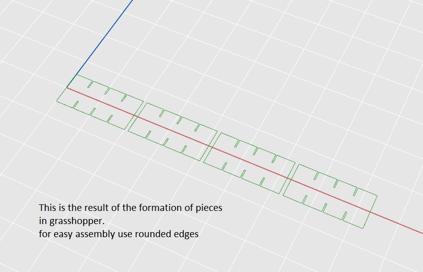
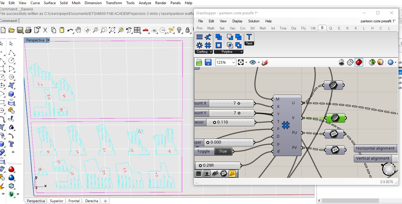
Modelled experimental objects/part of a possible project in 2D and 3D software
once decided a kerf of 3.3mm I use the waffle previously designed to approach the figure of the pantheon as an idea of the final project and cut the pieces for assembly
.jpg)
.jpg)
.jpg)
.jpg)
.jpg)
.jpg)
.jpg)
.jpg)
.jpg)
.jpg)
.jpg)
.jpg)
.jpg)
.jpg)
.jpg)
.jpg)
.jpg)
.jpg)
.jpg)
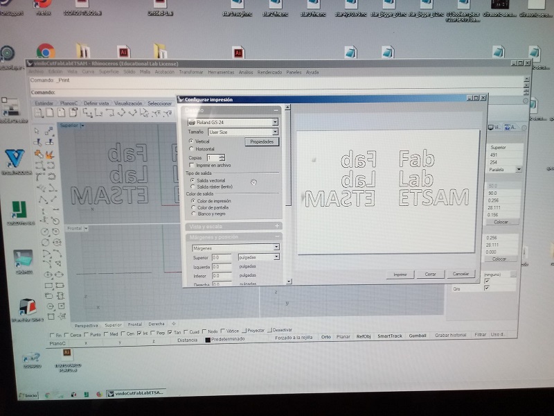
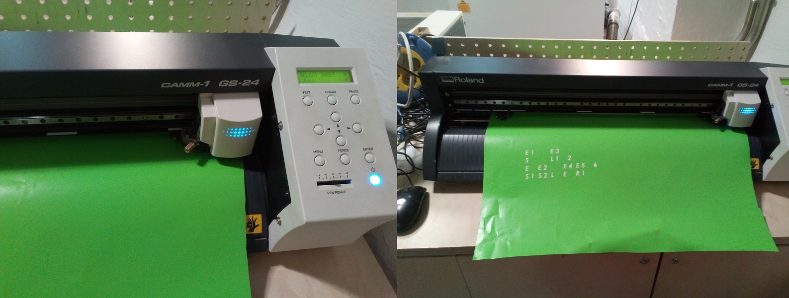
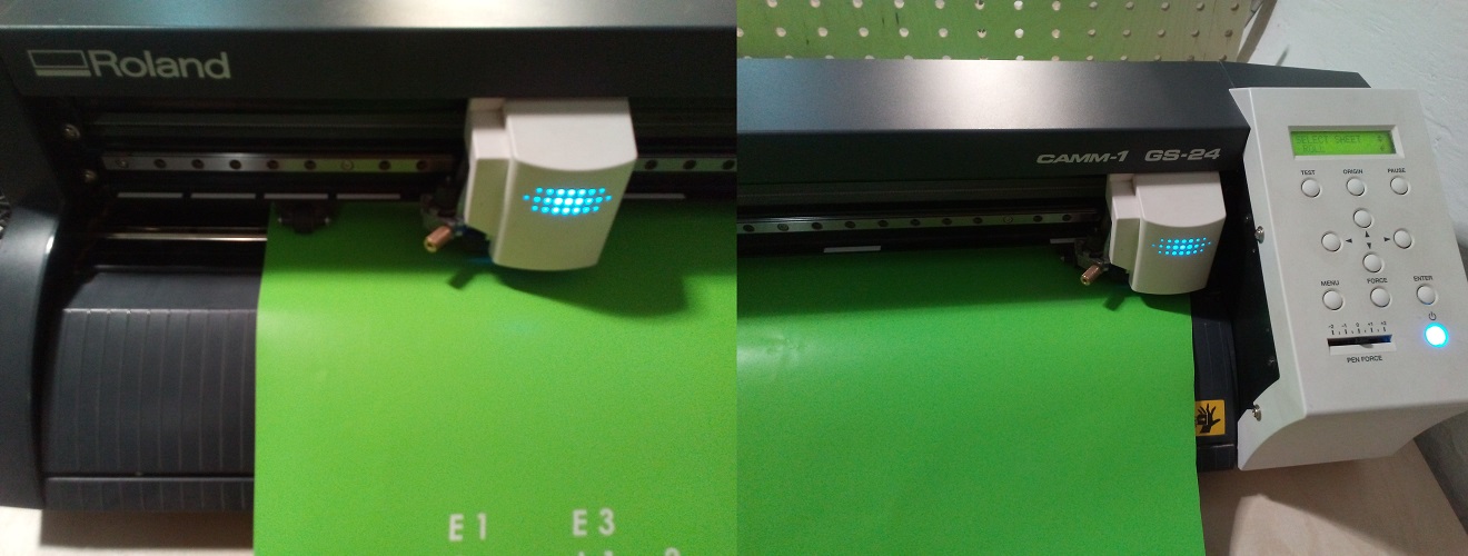
vinyl cut first

.JPG)
.JPG)
.JPG)
.jpg)
.JPG)
UPDATE CUT PARAMETERS
force/press: between 100 and 130.
Speed: Depending on the complexity of the design you want to send to work. It depends on the size of your most pronounced characters or contour
THE FORCE / PRESS, is the force exerted by the cutter towards
the material, therefore if we increase the Force value, the knife will crack the material with more pressure.
The idea is to find the maximum value of the Force, which sufficiently cracks the material, but that does not transfer / cut
the protection occupied by the Vinyl or Thermo transferable vinyl among others.
The Force value is different to use in each material, since it will depend on the width or thickness of it.
The Speed / Cut Speed, is how fast the Plotter's car will move, to do some work.
Now this parameter is important, since it must be adjusted to the size of the design to be cut and its complexity.
Therefore, if you need better definition
in certain areas, you must adjust the Speed parameter, in the following it indicates which Speed values, use depending on the size of the fonts.
font size
< 10 speed 10 to 20
font size 10 -30 speed 30
font size 50 - 500 speed 60
font size over 500 speed 80
.jpg)
.jpg)
.jpg)
vinyl cut second
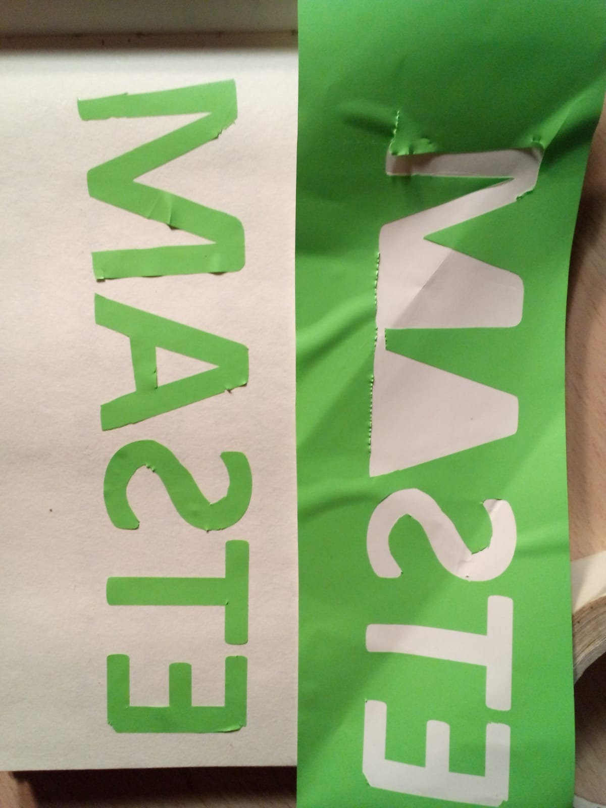
UPDATE : SECOND CUT DEFECTS AND PROBLEMS
This second cut is made with the same parameters, same conditions as the first. I had to repeat it only because the previous one was made in the facilities of the Higher Technical School of Architecture of Madrid. when repeating the same work in the fab lab of the IED madrid at this time and according to the managers there was no vinyl available. however I found a scrap with which I could carry out the work in its term. This scrap had a limited size and many wrinkles, which caused cutting defects to cause the blade to not always cut on a flat surface. On the other hand, according to the instructions of the people in charge, the blade was not well aligned or sharp enough due to its wear and tear. This motivated the repetition of the work already out of term by recommendation of my local evaluator.
vinyl cut third
In order to ensure a clear vinyl cutting process, I repeat the operation for the third time this time with a simpler logo
.jpg)
for that I created the logo in Rhino and from there I export the curves to Adobe Illustrator filling them with a plot
.jpg)
I introduce the vinyl and adjust the rollers as in the previous processes
.jpg)
in the rest of the process I made several tests adjusting the cutting pressure. in this with value 300 gr the blade cuts the paper of shelter also and even starts a little of the vinyl
.jpg)
in this with value 240 gr the blade cuts the logo cleanly, although still very deep lifting the paper
.jpg)
in this one with value 100 gr the blade cuts the logo cleanly, leaving intact the paper of protection and allowing the extraction of the logo easily
.jpg)