• Home
  • Machine group assignment
Machine
  • Scara Machine
  • 15. Machine Design

    This week we worked on tasks refered to Machine design in order to 'work and communicate effectively in a team and independently; design, plan and build a system; analyse and solve technical problems; recognise opportunities for improvements in the design'. This was the assignment:

    Group Assignment
    • Plan and make a machine.
    • Document the group project (Follow this link to see the group assignment)

    ASSIGNMENT | Machine plan and making

    Project management

    First thing was to review the tasks to be afforded in a new meeting after the class:

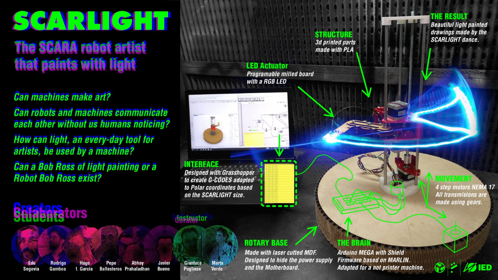
    Electrical components must be integred to the system, like power supply, wires and controller board (Arduino + Ramps).

    For that, some parts should be replaced/modified:

    Arm

    • The first arm gear had a bit little small hole to rotate around the axis than the desired/needed, so that piece was replaced for another one that allowed the movement to be easier.
    • The Arduino board was placed into the base into a simple MDF 3mm glued piece that allowed the easy put/remove action.
    • The central piece was re-designed and PLA 3D printed because of the big thickness of the whole wires that must be connected from the motors, LED actuator and end of career swithces to both the power supply and the Arduino controller. For that, the MDF 5mm rotatory base in where the tower is placed, had to be also cut with a bigger whole in which the central piece is placed with a new bigger bearing.

    Base

    • The motor should be well fixed to the base, so a piece was designed, produced and added specifically for that.
    • The last piece (LED actuator holder) must contact one of the 2 end of career switches, so it had to be modified for that, lasercut, and placed into the arm.

    Tower

    • The tower cap was a little bit broke because of the 3D printing resolution. In order to reinforce the axes fixing, this piece was 3D re-printed with higher in-fill settings to replace the first one.
    • The big piece that holds the 2 motors was a little bit bended by screw forces separating its 2 parts on the extreme. To solve that, a little acrylic 3mm fit system was designed, lasercut and added making it look nice than before.
    • All linear bearings were lubricated to help the whole big piece to slide better along the axes.
    • Also, it was very important to put together all personal capabilities to agree in the way to work.

    Programming

    Simmulations

    After reaching an agreement about the first idea of the machine, this is a simulation of its use in grasshopper. the behavior is simplified, and it should be understood that a led would light on each sphere that grasshopper draws

    starting to write code this is a simulation using arduino one where it is only intended to establish an order of execution. the green LEDs would light simulating the lit ones to draw, and the red one whenever there was a movement in z

    this simulation is similar, only that in this case a servo is assigned to simulate the behavior of the forearm

    • Base
    • Tower
    • Arm
    • Camera support

    Also, it has this other parts/components:

    • LED actuator (LED + board)
    • 4 motors:
      • Base rotation
      • Arm (Z movement)
      • Arm (whole rotation)
      • Arm (half rotation)
    • Spin ring (this component was finally discarded)
    • 3 shafts
    • 1 screwed shaft
    • Bearings:
      • 3 linear bearings (45x15x8)
      • 10 rotator bearings (7x22x5)
      • 2 rotator bearings (10x35x15)
    • Spacers
    • Arduino
      • Board
      • Case
    • Screws and nuts

    Project management

    To accomplish this goal, the Trello platform was used to organize the work by defining:

    • The design and its parts
    • BOM and material ordering
    • Tasks and people assignments
    • Workflow
    • Platforms

    This is the Trello in use, showing tasks, workflow and people in categories:

    This is the bom made:

    By this way, tasks were assigned to allow working on design before meeting again for the production process.

    Design

    These are the designs made based on the original one, using Rhino and Grasshopper, Fusion360 and Illustrator.

    Base

    Arduino case

    Camera support

    Production

    The processes followed to make the machine were 3D printing and lasercut:

    Base

    Results and problems

    Testing manual movement

    One of the problems founded was that the idea of using a slip ring for connections on a rotatory axis, was out of the bom plan; Adafruit is the only provider with high shipping cost and so much time to deliver the component.

    Another problem was that maybe the light would not be seen when the arm passes behing the tower, or if the LED holder hides the LED on some positions. One idea to solve this was to put the LED, extended with wires, at the end of the arm, while the controller board could be placed into the actuator piece near the tower. Another solution for that is to use all the faces of the actuator to hold different LEDs

    Final movements

    Light painting results

    Videos

    Original design files

    Download