Electronics Design
Introduction
This week our assignment was to:
Use the test equipment in your lab to observe the operation
of a microcontroller circuit board (group assignment)
Redraw the echo hello-world
board,
add (at least) a button and LED (with current-limiting resistor)
check the design rules, make it, and test it
extra credit: simulate its operation (individual assignment)
Choosing the right software
The fisrt thing I did, I compared KiCad and Eagle electronics design softwares. I found this comparison really informative. I have chosen Kicad, as it is free and open source, the component libraries are convenient, it has 3D viewer.
Cercuit design
I have used Neil's hello.ftdi.44.py
board as a referance and Babken Chugaszyan's guitar
board design
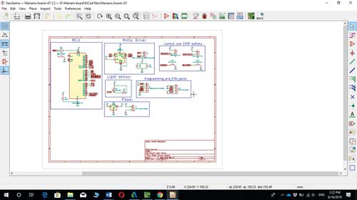
The first step was to choose ATtiny44A microcontroller and the other components (1 LED, 1k and 10k resistors,
20mhz resonator crystal, 1uF capacitor, 1 push button, 2 pinheaders) from the right hand side tools, next I have
added cercuit ground and +5v voltage in. 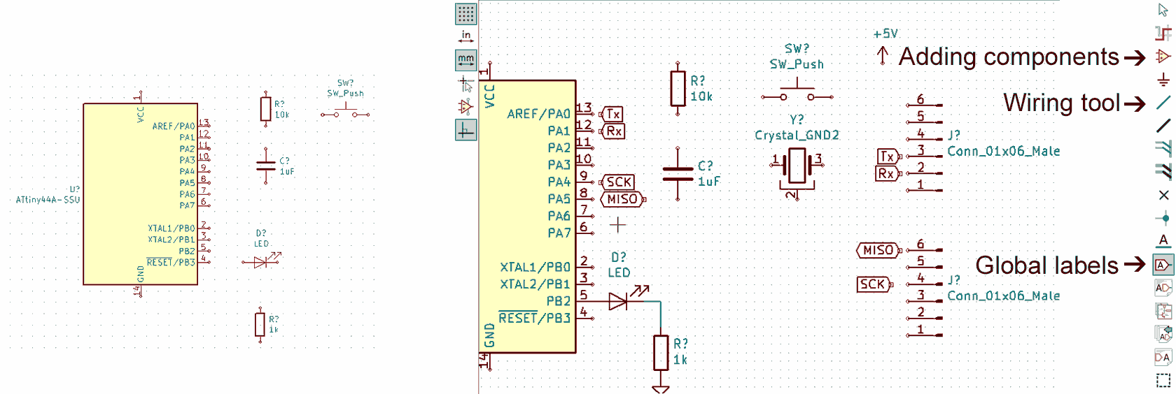 After that I have connected some of the pins using wiring tool and other pins using global
labels.
After that I have connected some of the pins using wiring tool and other pins using global
labels.
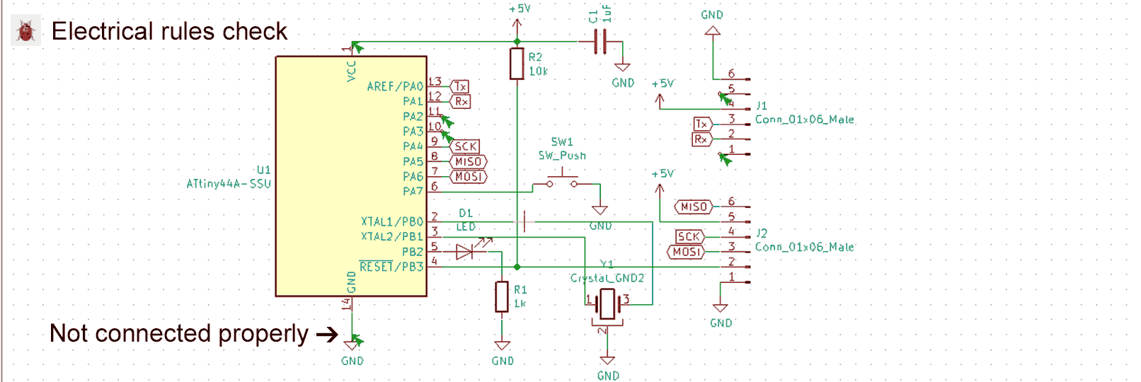
Next I used "electrical rules check" tool, found some mistakes and fixed them. For example the ATtiny44A microcontroller ground was not connested to the GND properly (see image below).
After I assigned each component a coresponding footprint by navigating to Tools>>Assign Footprints by
using SMD size 1206 imperial footprints for capacitor, resisitor, LED, then I annotated the schematics by
navigating to Tools>>Annotate Schematic and generated the netlist by navigating to Tools>>Generate
Netlist File.
Here are KiCad files echo-mariam-v1
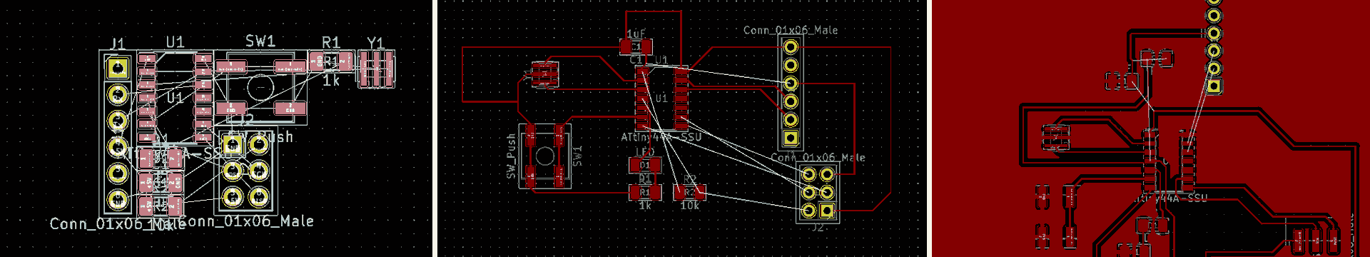
I opened the "PCB layout editor", chose the "read netlist" tool and started classify the components, that would be on the convenient directions, by rotating, by hitting "R" letter. After connetcted all components, I used "add filled zones" tool, got my PCB are and started drawing the tracks,
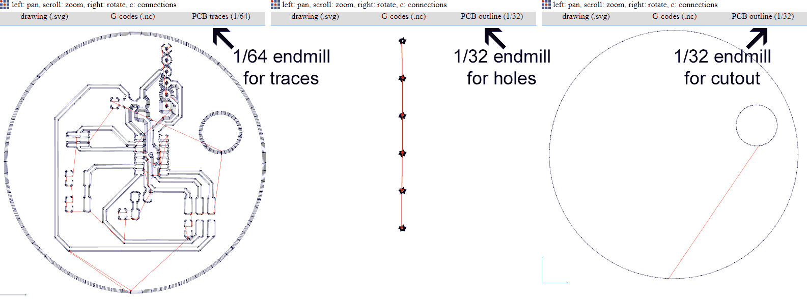
Next I exported 3 SVG files:
One for PCB traces (click to download)
Second for Pinheader holes (click to download)
Final one for Cutout (click to download).
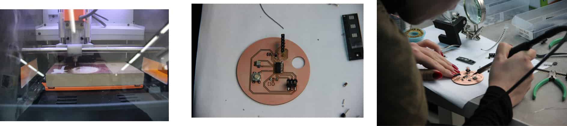
PCB milling
Then I went to Fabmodules.org to generate toolpaths and G-codes in order to mill the board. I used 1/64 endmill for milling the traces, 1/32 endmill for the pinheader holes and cutout.
 I found this video on youtube, and it helped me to start cutting with SRM 20 milling machine.
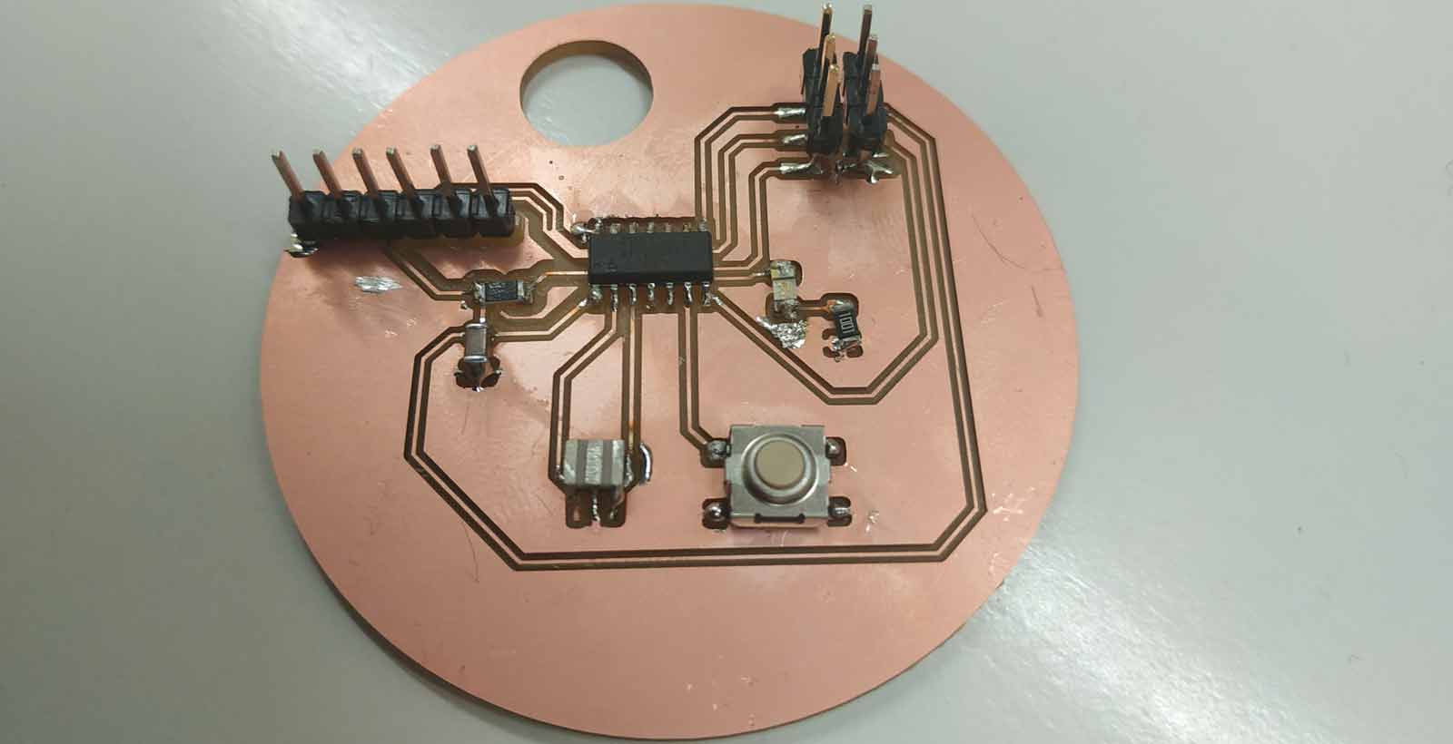
Soldering
After the milling the board I have washed it and started soldering. During the soldering process I did some mistakes, but at the end I finished it.
Design of new board
This week I decided to start my final project's board.• Opened Kicad
• Selected components I am going to use
• Start drawing
List of components necessary for the board
I am going to use Atmega328 microcontroller
• Light sensor
• button
• switches
• motor driver
• resistor etc.