
Mechanical and Machine design --- Մեխանիկական և Մեքենայի նախագծում
Introduction --- Ներածություն
For this week we had to: (group assignment)
- actuate and automate your machine
- document the group project and your individual contribution
Developing a plan --- Կազմակերպում
Let me intruduce our team:Mariam Nahapetyan
Miqael Aramyan And me.
Our team considered several options of machine:
CNC mill
2D plotter
3D printer
An automatic 3D scanner
We even thought of a machine to automate Dilijan Fablab's entrance gates.
At some point we realised that everyone of us acqured the capabilities and confidence to
make each and all of them! And that confidence in my estimation is one of the greatest
assets we want to develop through our study. Making something by yourself is one thing as a team
completly different.
Ladies and gentelman this is the machine we made!
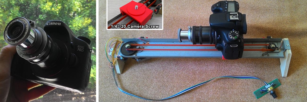
At first glance it might appear rather simple and it's function not clear, but it's very inteligent and useful tool. It has actuation (stepper motor), two end switches and a control (brains) and a custom made camera holder. And all of this works!! :) This machine could serve as a camera dolly:
And as a focusing rail.
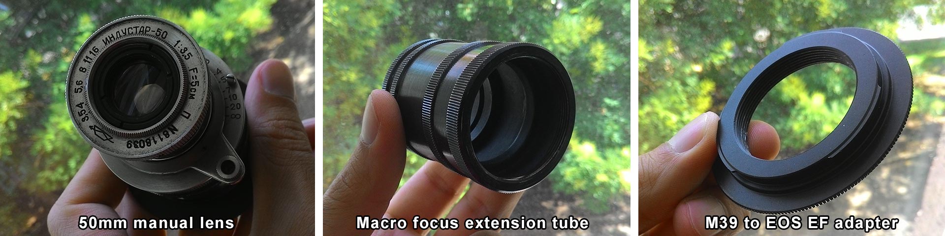
I used Canon 70D as a camera with an old soviet lens "Индустар-50" that has M39 mount. I used M39 to Canon EF mount adapter and an old soviet M39 macro ring. You can get the old lens and the ring in Yerevan market called "Vernisage" for about 20$.
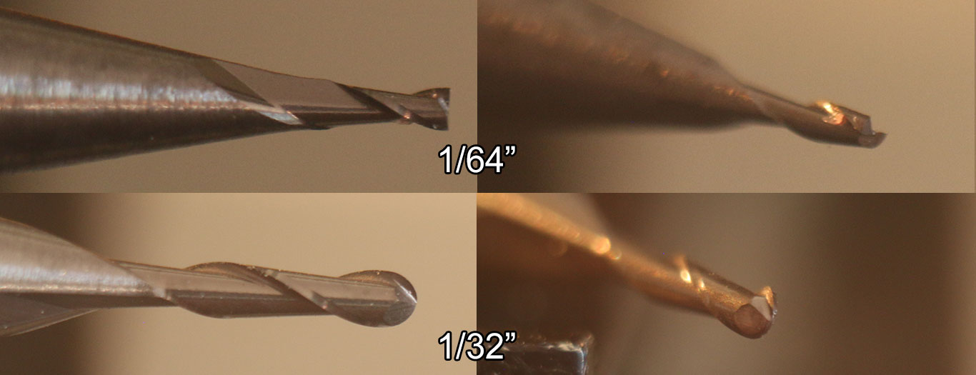
By fine adjusting the distance between the object and the lens you can get sharp macro images like this I got for our PCB milling bits.
During our output devices week one of the things we learned was how to program and drive
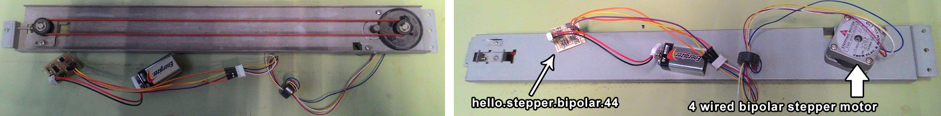
motors. During that week I found a floppy drive and a bipolar stepper motor with
a rail and it's timing belt I tested Neil's hello.stepper.bipolar.44 board with those and was
very excited with what I learned.
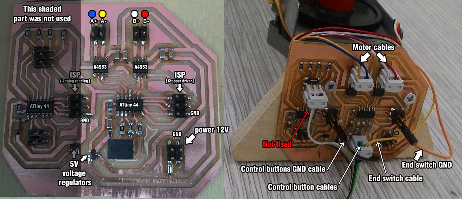
A week before (input devices week) we learned how to connect buttons, and sensors to a system. By the way this two weeks changed my attitude towards automation. Before I considered automation as something expensive and available only to smart people, now I consider automation as something fun, affordable and very easy. We took that rail and used it as a foundation for our machine. The PCB board I designed for my final project was initially designed to drive 2 DC motors, it has two A4953 full bridge motor drivers that are controlled by ATtiny44 microcontroller. This board is overengineered for our machine because it has 2nd ATtiny44 to read 4 analog inputs and send commands to other ATtiny44. I made two of this boards one as a backup, and since it was not used I decided it's better to save both components and time and use my spare board to drive our machine.
Our rail needed a part that will be attached to the belt, carry the camera and slide on the rail. In order to make we need to measured the dimensions and model the part.
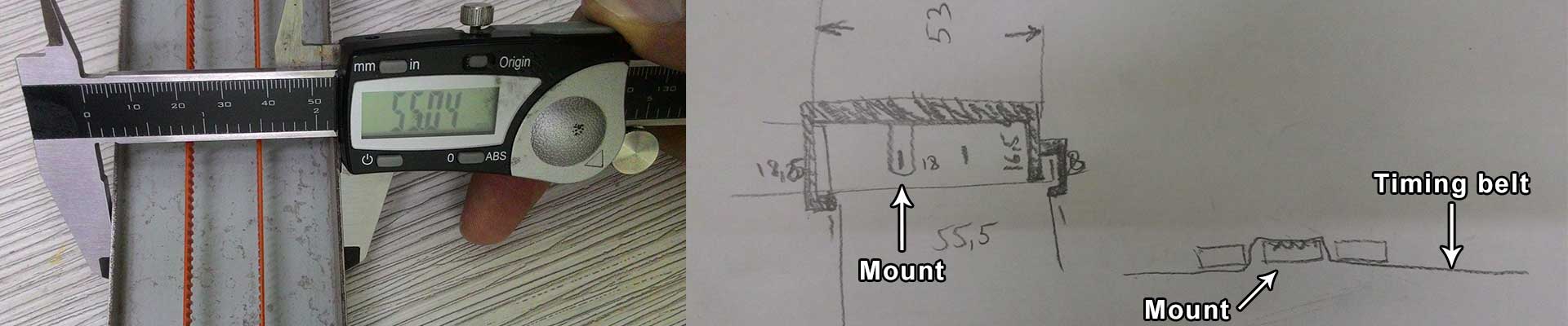
We used Fusion360 to model the part. It has three legs that grab the belt. And a hole which enables to mount camera.
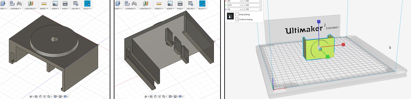
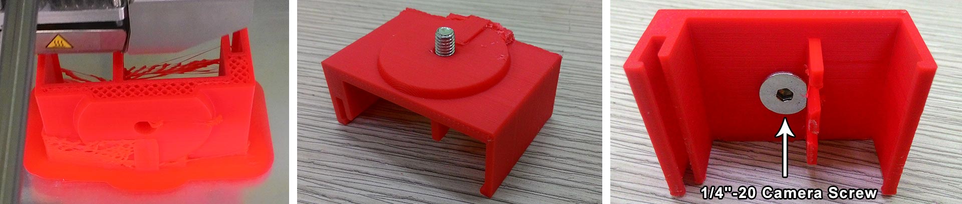
We 3d printed the part from ABS using Ultimaker 2 3d printer. Then we took a 1/4"-20 hex bolt and inserted into the hole. This bolt will enable to attach different cameras and devices to our dolly. in our case it's Canon 70D.
Here are the files for mount.
STL file (3d print ready) slider v1.stl
Fusion file slider v2.f3d
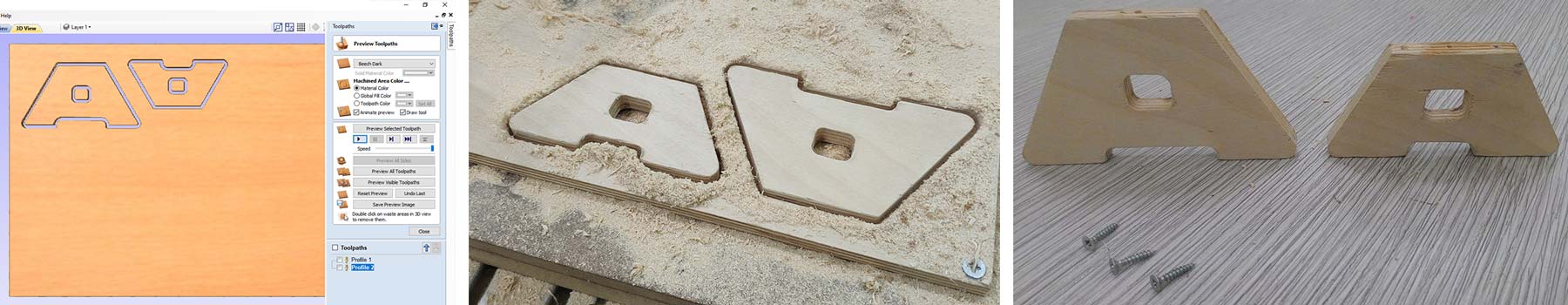
Then Michael Aramyan designed the legs for our dolly with Vcarve Pro. And milled them from a piece of 10mm plywood using Shopbot machine.
Here is the file for machine legs.
Vcarve file machine legs.crv
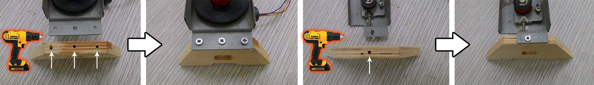
Then I made the holes for screws with a screwdriver and 3mm drill bit. And finally attached the legs to the rail using screws.
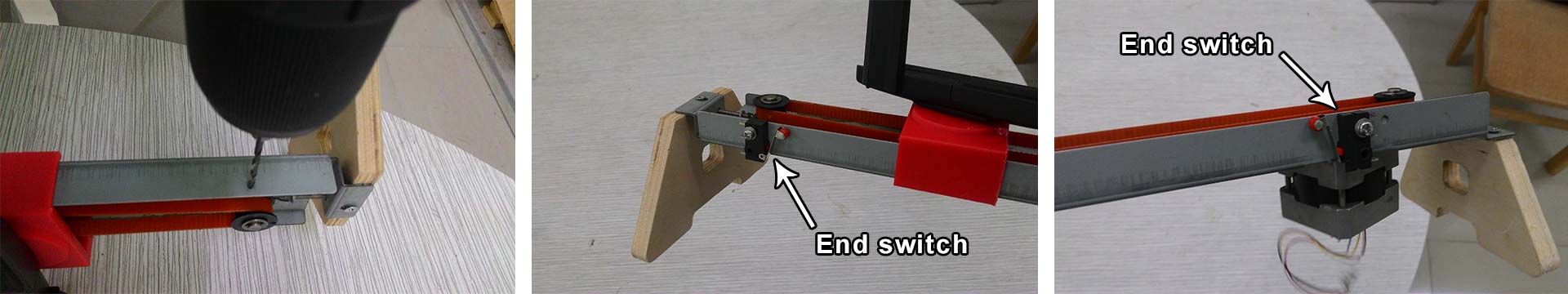
We needes two end switches to stop the motor when the mount gets to the one of two ends of the rail. I made two holes on the side of each end of the rail to mount the end switches. Then I attached them to the rail.
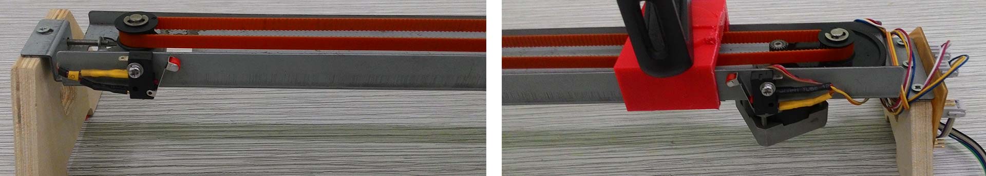
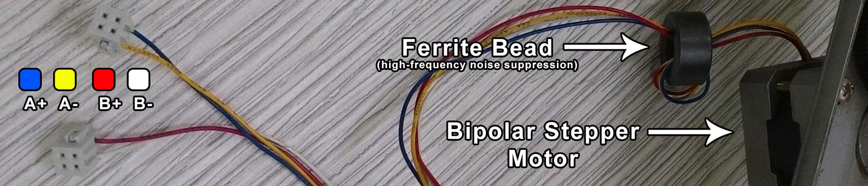
Then I added female pinheaders to the stepper motor wires. The color code is shown in the picture below. Our motor had a Ferrite bead on it so I decided to leave it there.
Board -- Տպատախտակ
In order to operate this machine we need 4x digital inputs (2x buttons and 2x end switches) and 4x digital օutputs connected to 2x A4953full bridge (1x Stepper motor). During my Final project development I made an extra board that had that had all this parameters. I made two of those boards and used only one the second one was not used so I decided to use it. It uses 12V as power.
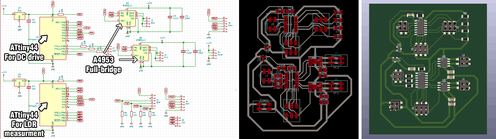
Here are the Kicad PCB files:
solar_v1 kicad.zip
Here is the png file of the PCB:
pcb png.zip
The Code -- Ծրագիրը
Let's understand the code. I'll jump to main loop to make it easy. If you want to see detailed explanation of libraries and variables declared visit my Embedded programming assignment.
Main Loop
Our both end switches are connected to one input pin PB1 that is named in our program "input_pinu"
Our left button is connected to pin PB0 and is named in our program "input_pino"
Our right button is connected to pin PB1 and is named in our program "input_pini"
#define input_pino (1 << PB0) //left button pin
#define input_pini (1 << PB2) //right button pin
#define input_pinu (1 << PB1) //end switches pin
while(1){ // Forever loop
int a=0; //declare a variable named "a" with integer type "int"
if (0 == pin_test(input_pins,input_pino)) //if the left button is pressed
{if (0 == pin_test(input_pins,input_pinu)){ //if one of the end switches is pressed
for (a=0; a<50; a++){ //Move to a safe position from left corner (50 steps clockwise)
step_cw();}//Move to a safe position from left corner (50 steps clockwise)
while(0 != pin_test(input_pins,input_pini)) //while right button is pressed
{;}} //do nothing
else { //if right button is not pressed while left is pressed
step_ccw();}} //turn motor counter clockwise
if (0 == pin_test(input_pins,input_pini)) //if right button is pressed
{if (0 == pin_test(input_pins,input_pinu)){ //if one of the end switches is pressed
for (a=0; a<50; a++){//Move to a safe position from right corner (50 steps counter clockwise)
step_ccw();}//Move to a safe position from right corner (50 steps counter clockwise)
while(0 != pin_test(input_pins,input_pino)) //while left button is pressed
{;}}//do nothing
else {//if left button is not pressed while right is pressed
step_cw();}}}}//turn motor clockwise
Here is the c code and make file:
machine.44.c
machine.44.make