
Networking --- Ցանցեր
Introduction --- Ներածություն
For this week we had to:
Design, build, and connect wired or wireless node(s)
with network or bus addresses (individual assignment)
send a message between two projects (group assignment)
I decided to use Neil's hello.bus.45 PCBs for RS-232 standard.
I've made and tested:
1 bridge
2 nods
Making of the PCBs --- Տպատախտակի պատրաստում
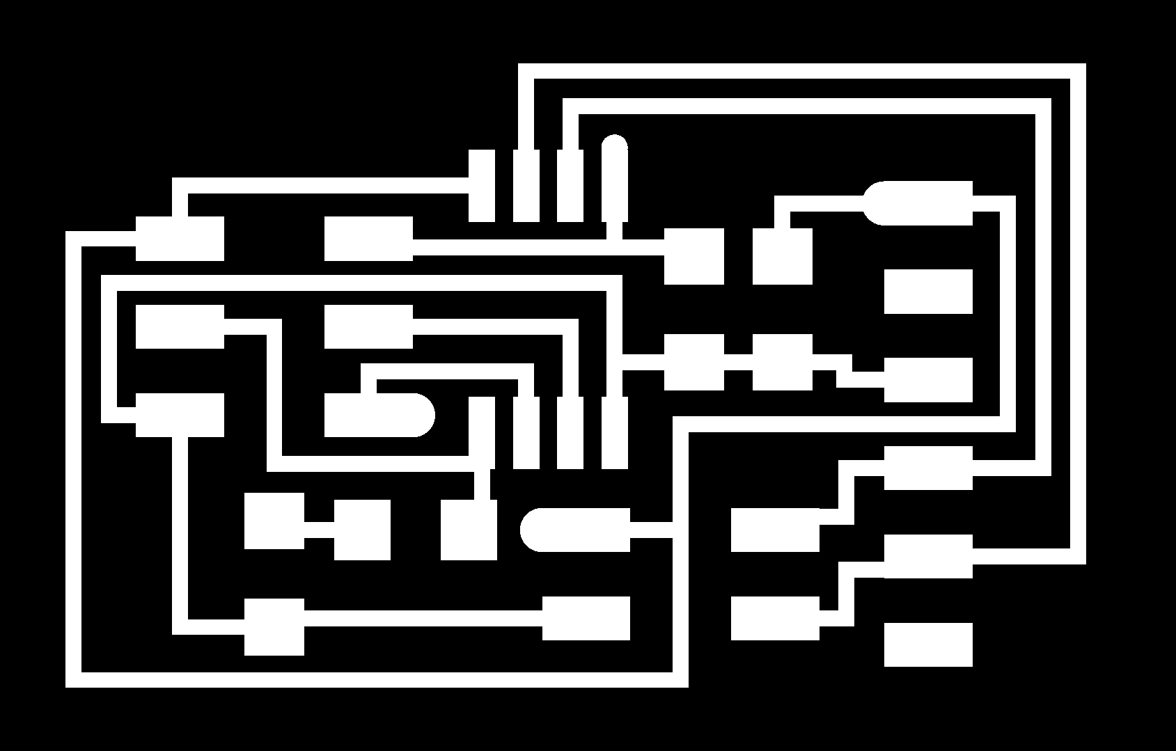
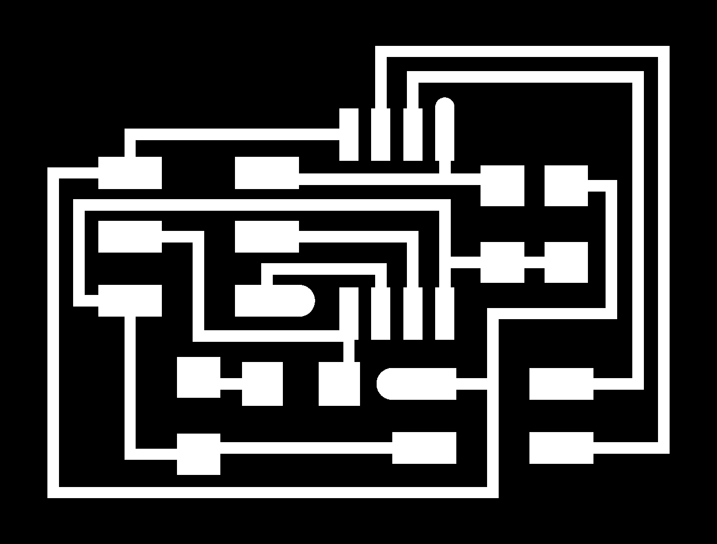
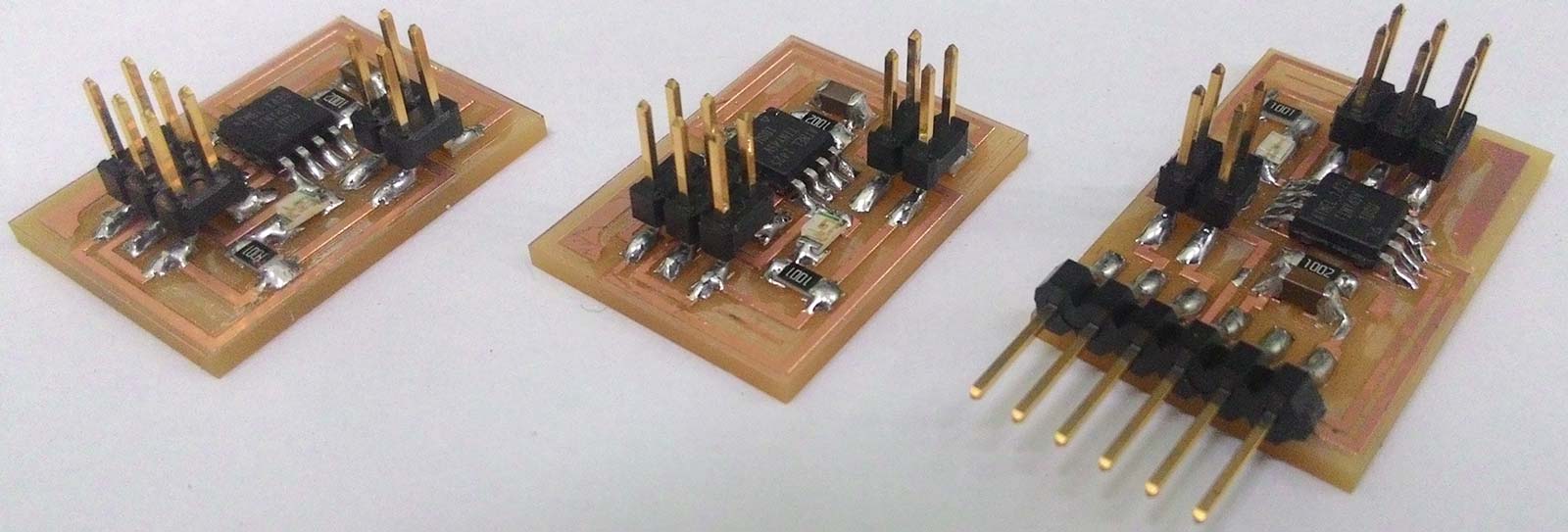
Here are the hello.bus.45 boards:
hello.bus.45.bridge traces,
and it's interior
hello.bus.45.node traces,
and it's interior
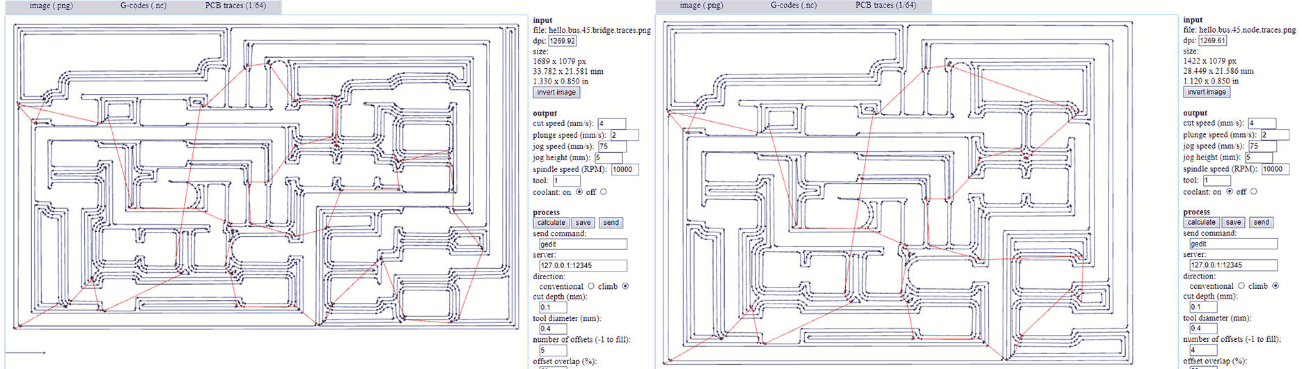
I used Fabmodules to generate the toolpaths. To learn how to use Fabmodules you can check this tutorial. I changed the "number of offsets" value from 4 to 5 to have less extra copper around the traces. That makes soldering process easier. but I advise to make it 7.
Soldering the components --- Բաղադրամասերի զոդում
You can find the component list in Neil's keynotes for Networking and Communications but I will post them here too.
hello.bus.45.bridge board needs
1xATtiny
45
1x1k SMD 1206 Resistor
1x10k SMD 1206 Resistor
1xLED SMD 1206
1x1uF SMD 1206 Capacitor
1x 2x3 male pin headers (For ISP)
1x 2x2 male pin headers (For Power & Com)
1x 6 pinheader (For FTDI cable)
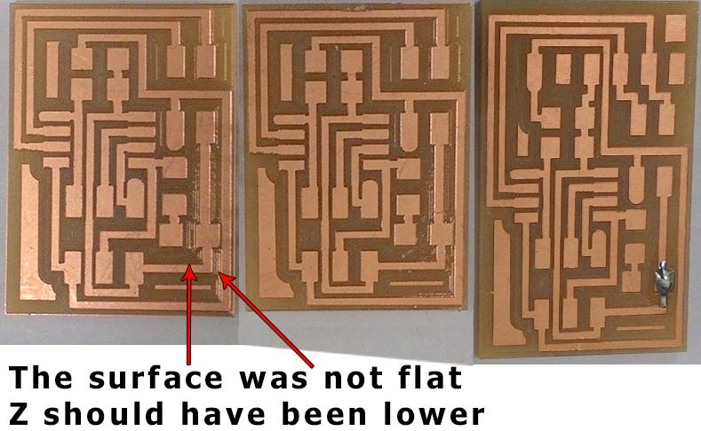
Here are the ready PCBs
hello.bus.45.node board needs
1xATtiny
45
1x1k SMD 1206 Resistor
1x10k SMD 1206 Resistor
1xLED SMD 1206
1x1uF SMD 1206 Capacitor
1x 2x3 male pin headers (For ISP)
1x 2x2 male pin headers (For Power & Com)
RS-232 serial communication --- Հաջորդական կապ
RS-232 of TIA-232 is a standard of serial electrical signal communication first introduced in 1960. During one of our lectues Neil said that RS-232 is a reliable "ancient" standard. In order to understand what RS 232 is we need to understand what serial communication is. In telecommunication Serial communication is called a process when data is sent consecutively biy by bit in contrast parralel communication is when data is beeing sent in bytes (8bits) via parralel links. Serial is much slower than parralel but is cheaper and easier to impliment.
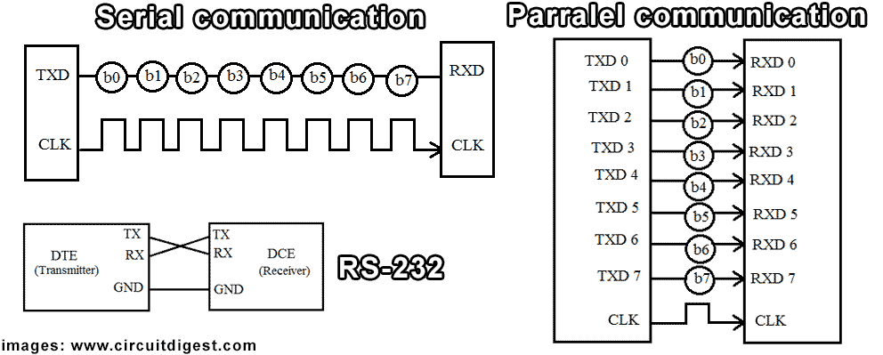
One of characteristics of serial communication is Baudrate it defines the speed of transmission. In other words it's the number of bits passing in one second.
Programming --- Ծրագրավորում
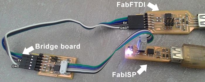
I used Ubuntu and FabISP we made on week5 to program the boards and FabFTDI I made to power the boards and serial communication. In order to program this boards we will need the C codes, and makefile from the Networking and Communications keynotes. Here are direct links C code and makefile. My advice is to keep them in separate folder and name it accordingly (network).
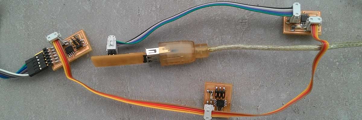
Connect your usbtiny (FabISP) to the hello.bus.45.bridge board's ISP port using the ISP cable, connect FTDI cable to board's FTDI pins as shown in the image below and finnaly connect FabISP to the USB port of the computer
For programming the Bridge board you will need
- An Ubuntu computer with "avrdude" and "avr-gcc" installed (Need to install? go HERE)
- FabISP with ISP cable
- FabFTDI or FTDI cable to power the board and to communicate
- For FabFTDI change
#define bit_delay_time 100in the C code from 100 to 208.3 that's the baudrate delay time for 4800bps. (Default value 100 is for 9600bps) - C code
- makefile
Type this command and hit enter:
make -f hello.bus.45.make program-usbtiny
-f scecifies the makefile's name in this case it's "hello.bus.45.make"
program- specifies the programmer we're going to use in our case "usbtiny"
(!!! if you use other programmer change "usbtiny" to "avrisp2" or "dragon_isp" !!!).
Overall this command makes the .hex file based on the libraries and the C code.
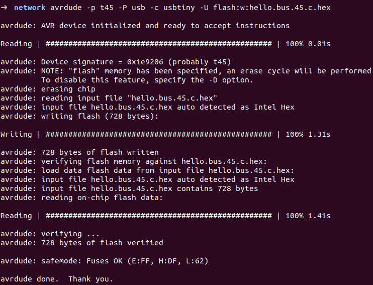
If everything goes right you should see this message
Next type this command and hit enter
avrdude -p t45 -P usb -c usbtiny -U flash:w:hello.bus.45.c.hex
-p scecifies the AVR device in our case t45 (ATtiny45)
-P specifies the connection port in our case USB port (FabISP)
-c specifies the programmer type in our case it's usbtiny
(!!! if you use other programmer change "usbtiny" to "avrisp2" or "dragon_isp" !!!).
-U specifies a memory operation (multiple options available)
in our case "flash" flashes the ROM, "w" reads the .hex file and writes it to the memory.
If everything goes right you should see this message. Congradulations you're done!. Close the terminal.
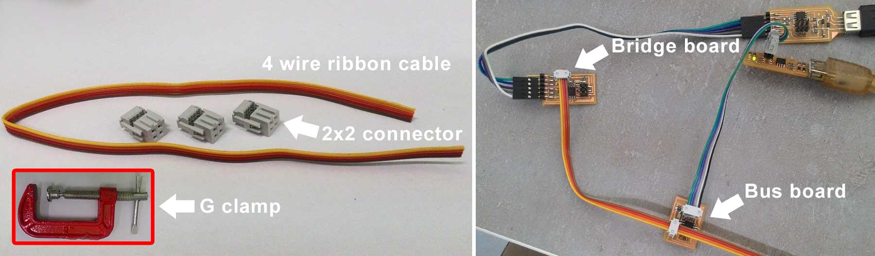
Now get a 4 wire ribbon cable about 30cm and 4 2x2 connectors shown in the image below. Clamp the connectors to the ribbon cable (I used G clmp to press them) Now disconnect ISP cable from the Bridge board and connect the ribbon cable to the bridge board and to the bus boards (see image below) with the 2x5 connector to the board as shown in the image below.
Now go ahead and find the #define node_id '0' line in the C code and change '0' to
'1' in order to have unique id for each board. Save the file.
Connect your usbtiny (FabISP) to the node board's ISP port using the ISP cable
as shown in the image above.
Again open the "network" folder right click and select "Open in Terminal" option
again type this command (or hit up arrow key and find this command) and hit enter:
make -f hello.bus.45.make program-usbtiny
Next type this command (or hit up arrow key and find this command) and hit enter
avrdude -p t45 -P usb -c usbtiny -U flash:w:hello.bus.45.c.hex
Now find #define node_id '1' line in the C code and change '1' to
'2' in order to have unique id for next board. Save the file.
Connect your usbtiny (FabISP) to the next node board's ISP port using the ISP cable
as shown in the image below.
Agan open the "network" folder right click and select "Open in Terminal" option
again type this command (or hit up arrow key and find this command) and hit enter:
make -f hello.bus.45.make program-usbtiny
Next type this command (or hit up arrow key and find this command) and hit enter
avrdude -p t45 -P usb -c usbtiny -U flash:w:hello.bus.45.c.hex
Remove the ISP cable. Download term.py to the same "network" folder.
You need term.py to send and monitor serial data. Open the "network" folder right click and select "Open in Terminal".
Type this command ls /dev and hit enter. This command lists the devices connected.
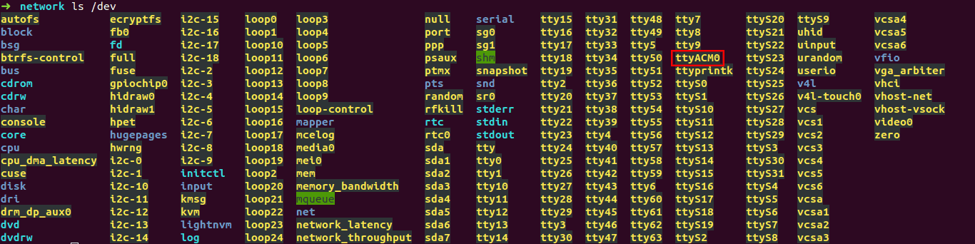
In our case our FabFTDI is listed as ttyACM0. In case of FTDI cable it should be ttyUSB0.
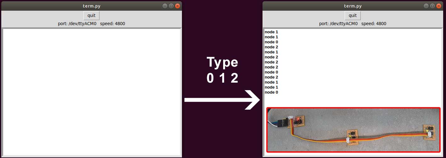
Now type this command sudo python term.py /dev/ttyACM0 4800 (if you use FTDI cable change 4800 to 9600 and ttyACM0 to ttyUSB0.)
hit enter.
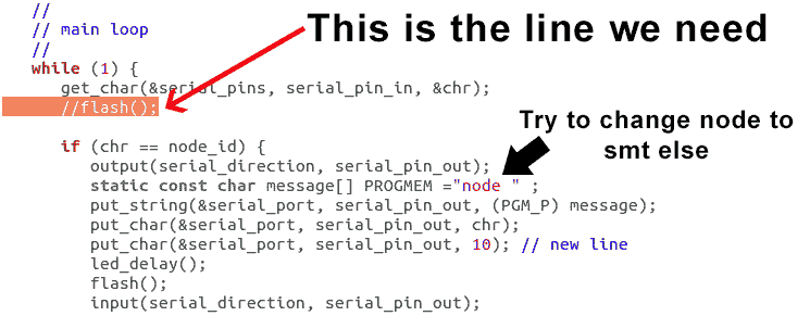
- Since the LEDs blink all the time it's hard to tell which node responds when. There's a solution to that just change
flash();to//flash();in the C code (see the image) and only the responding node will blink. - Here are all my files ziped
- hello.bus.45