-
Assignment
Mechanical DesignMechanical Design
In this week assignment, We have to design a machine (mechanism + actuation + automation), build the mechanical parts and operate it manually as a group. And then document the group project in addition to document the individual contribution
We did a brinstorming session with my frineds Mass & Hussain and we planned to do somthing as a group. We started thinking of making a machine that sorts the colors
The project can take a set of colors and sort them by directing them different containers. This can be done using many mechanisms, but we are planning to make a conveyor that does the job. By attaching electronics components later to sense the colors and a microcontroller board that decides which path is heading to the right container using DC and servo motors
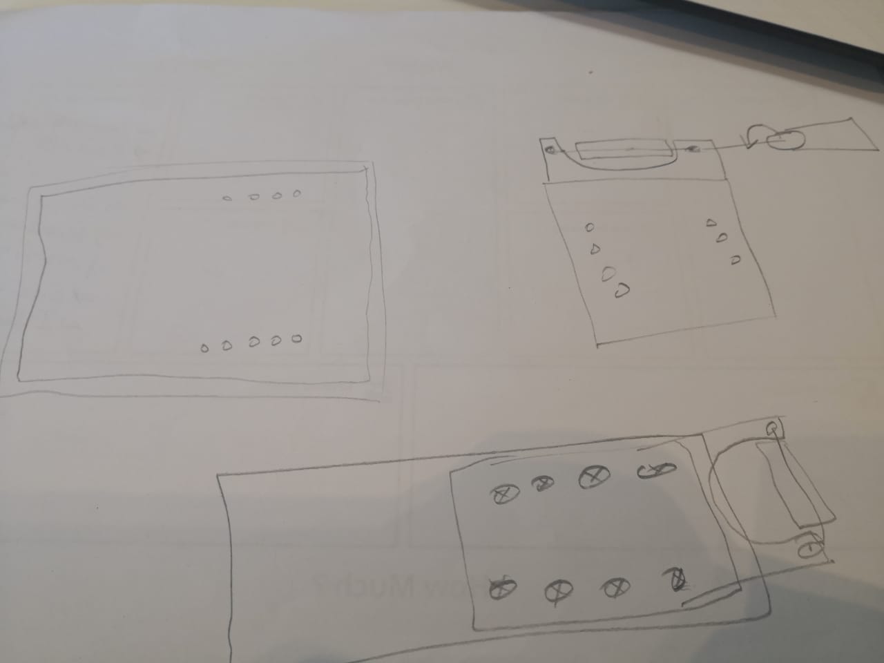
We started doing a sketch in the brainstorming session, using some papers and trying to think and work as a group before using any digital tool. Then we end the session with a clear vision to work and a plan to start drafting something and get back again to discuss the progress and share what we have done
The simple sketch that I have done during the brainstorming session was illustrating the base to hold the project with the part where the berings will be fixed and the shaft rotating
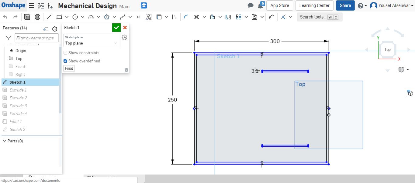
The use of digital tools can support more my thoughts, therefore, I created a new document using Onshape to implement what I have in mind and check the 3D parts
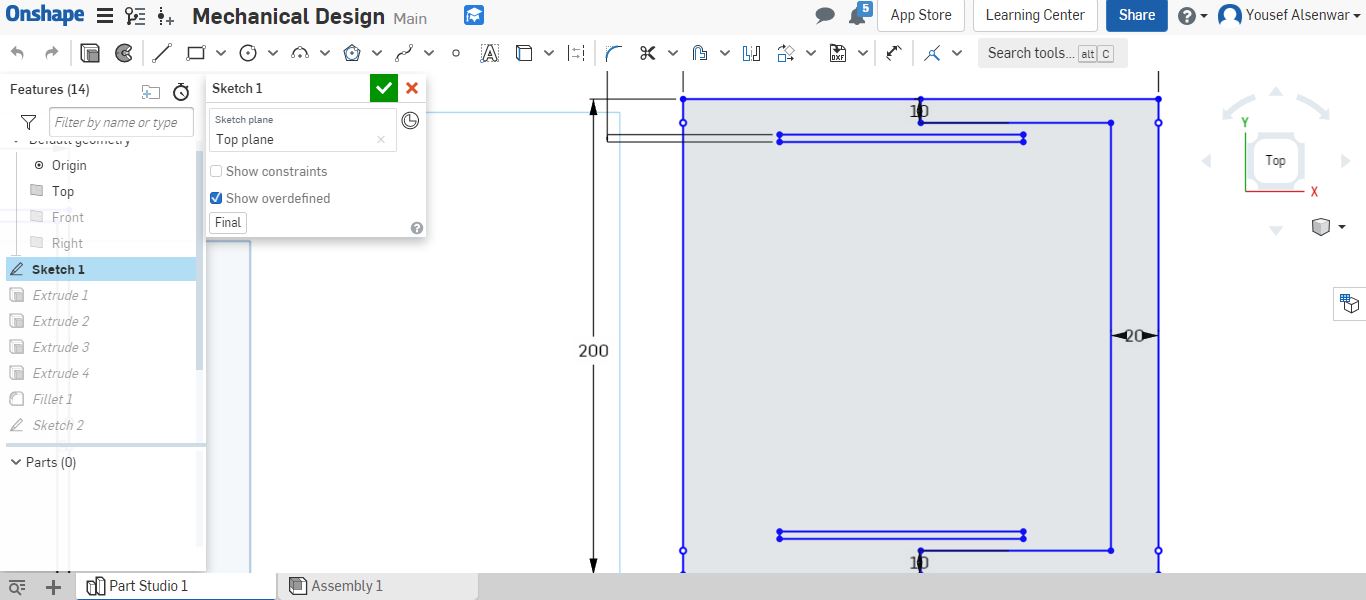
By hiding two planes and keeping the top to create a sketch on it. The base should have holes to fix the parts on it, also a simple base to make sure that the edge of the screws or nuts will not touch the surface; to make the base stable with no vibration or something. Adding a rectangular with dimensions 300mm * 250mm, also adding two rectangulares width 3.1mm to fit the screws. I used offset to add 5mm lines inside to build the edges in the bottom
The interior rectangular needs to be extruded from one side 6mm (I will print it using 3D printer later or laser cutter using 6mm acrylic). I selected it and clicked on the extrude icon and set the depth as 6mm
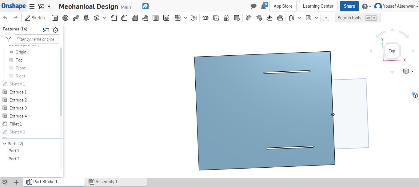
The outer closed path is meant to be extruded from both sides (symmetric) by 12mm to keep 6mm from the bottom side to stabilize and hold the model when we fix the nuts
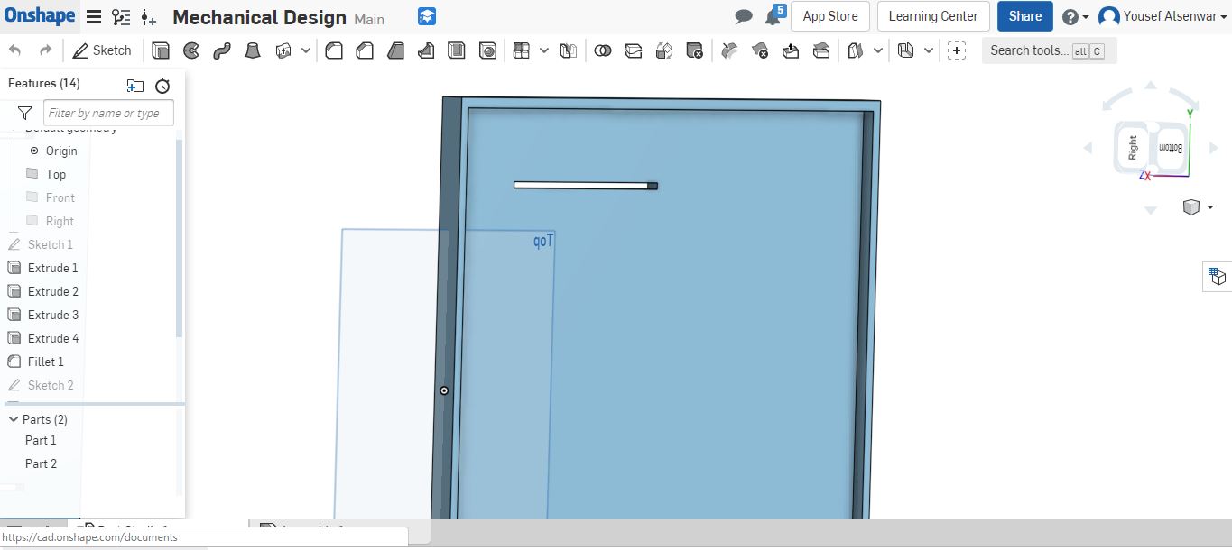
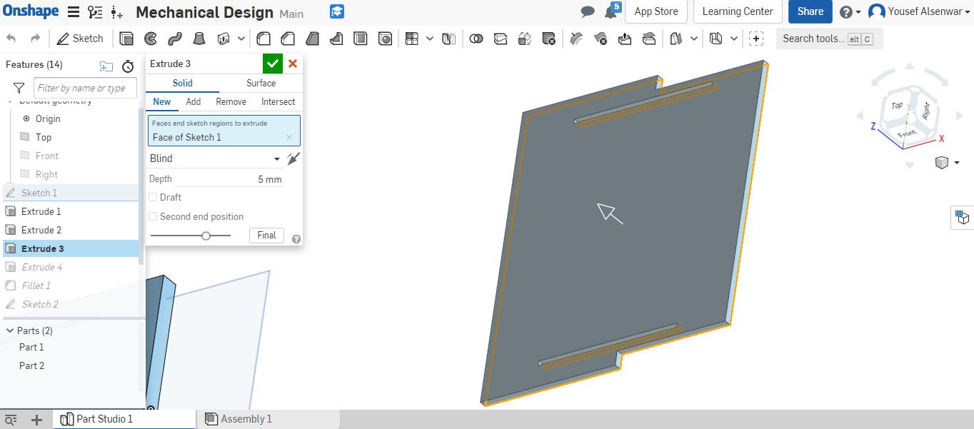
The first part is done. The second part should be designed to be fixed on the top of the first part. And the berings where the shaft will rotate. I did the sketch using rectangular, some lines, and trim tools
The main part should be extruded to be the base for the whole design. The depth is 5mm
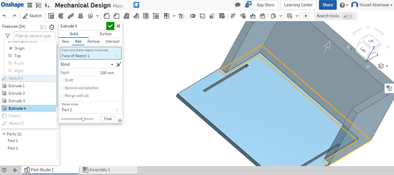
I extruded the rest by 100mm as I’m going to hold the mechanism (motor, shaft, bearings)
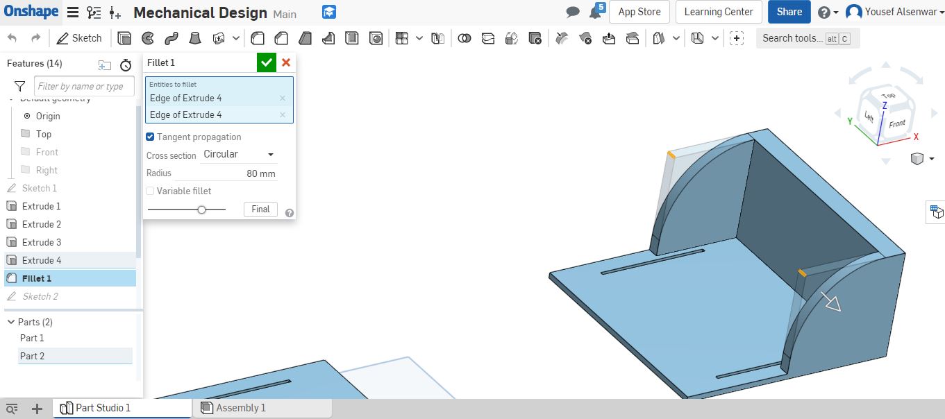
I did use fillet to make the slide edge diagonal as no need to keep them big like this, also to make the use of the screws easier in the top
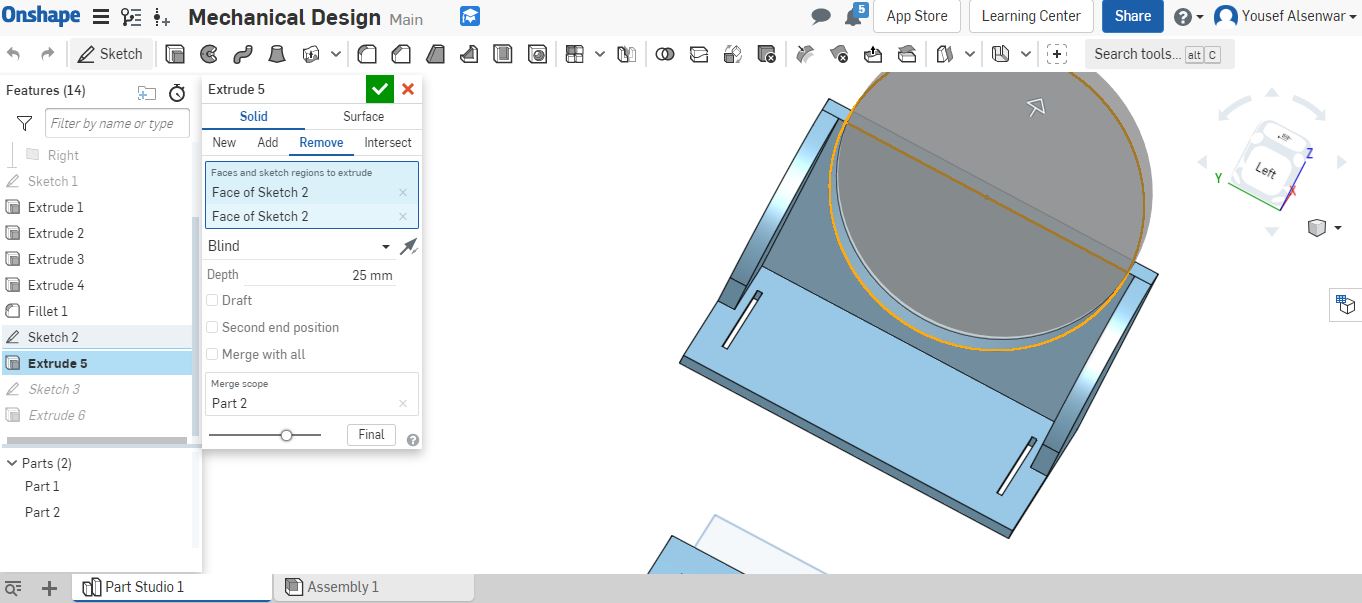
I created new sketch to remove the additional material to make the shaft movement easier and to have the space. The circle that I did was 171.1mm in diameter and the center is the same center of the rectangular line to be symmetric when the material is removed

By clicking on the extrude and then remove, I removed the material
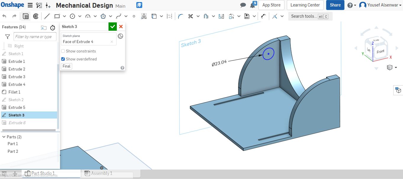
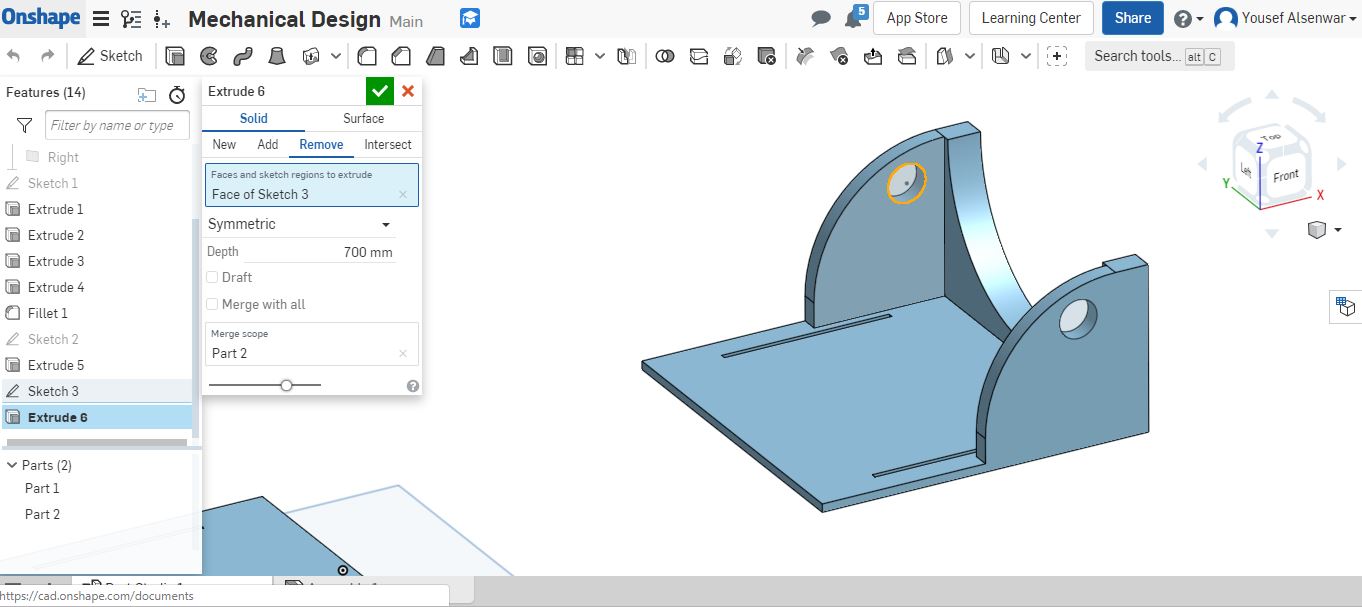
I started a new sketch on the plane that is the side of the model to do the circle for inserting the berrings to fix the shaft inside
I remove the material with symmetric to remove both sides
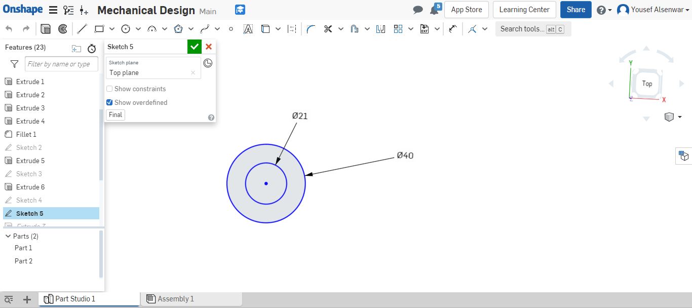
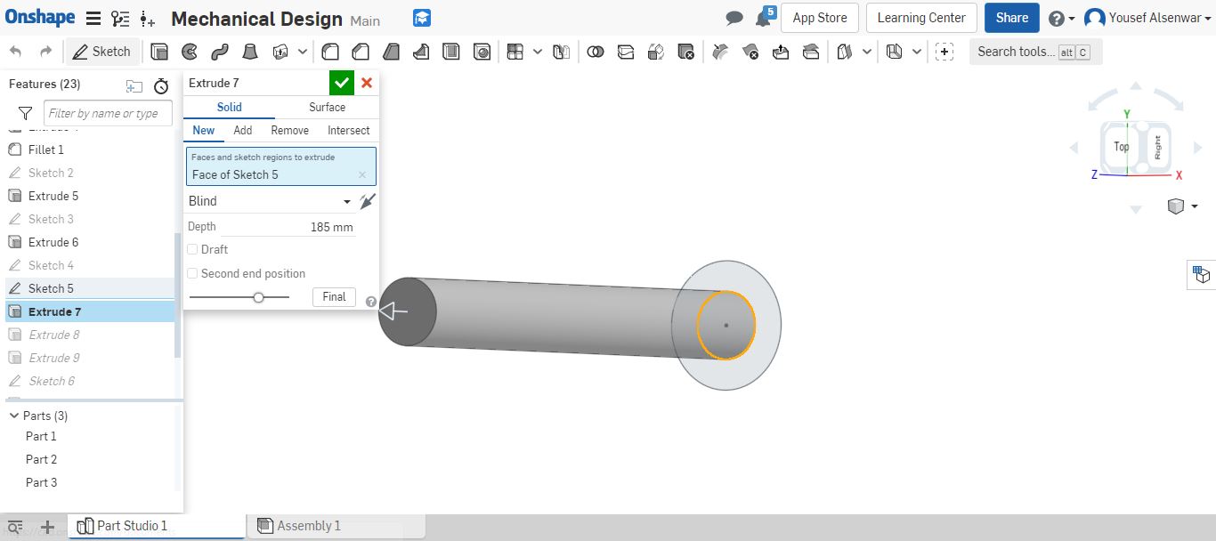
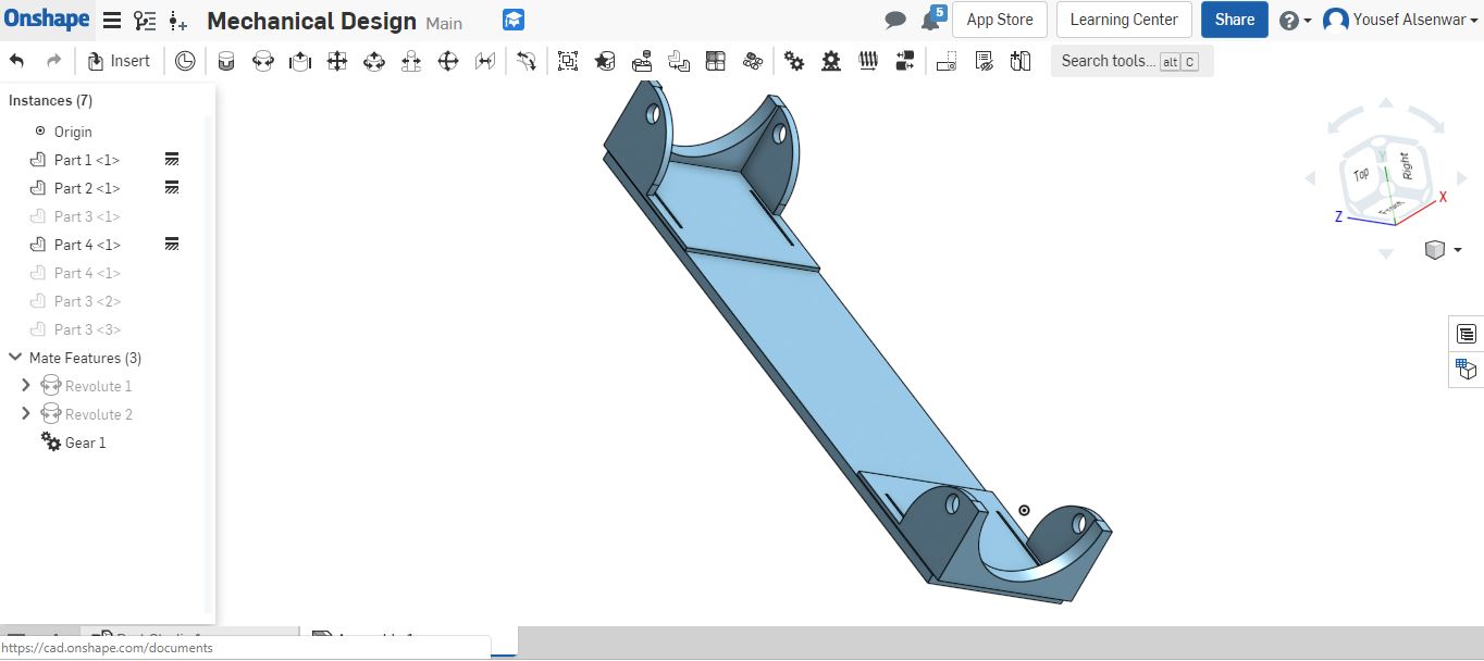
Now, I can build the shaft with lever to move the mechanism manually. To do that I need to create new sketch with two circles, one to fit the bearing and the another one to move the belt
Extruding the inner circle by 210mm, but one side 185 and the other side 25 to get the total and symmetric with outer circle
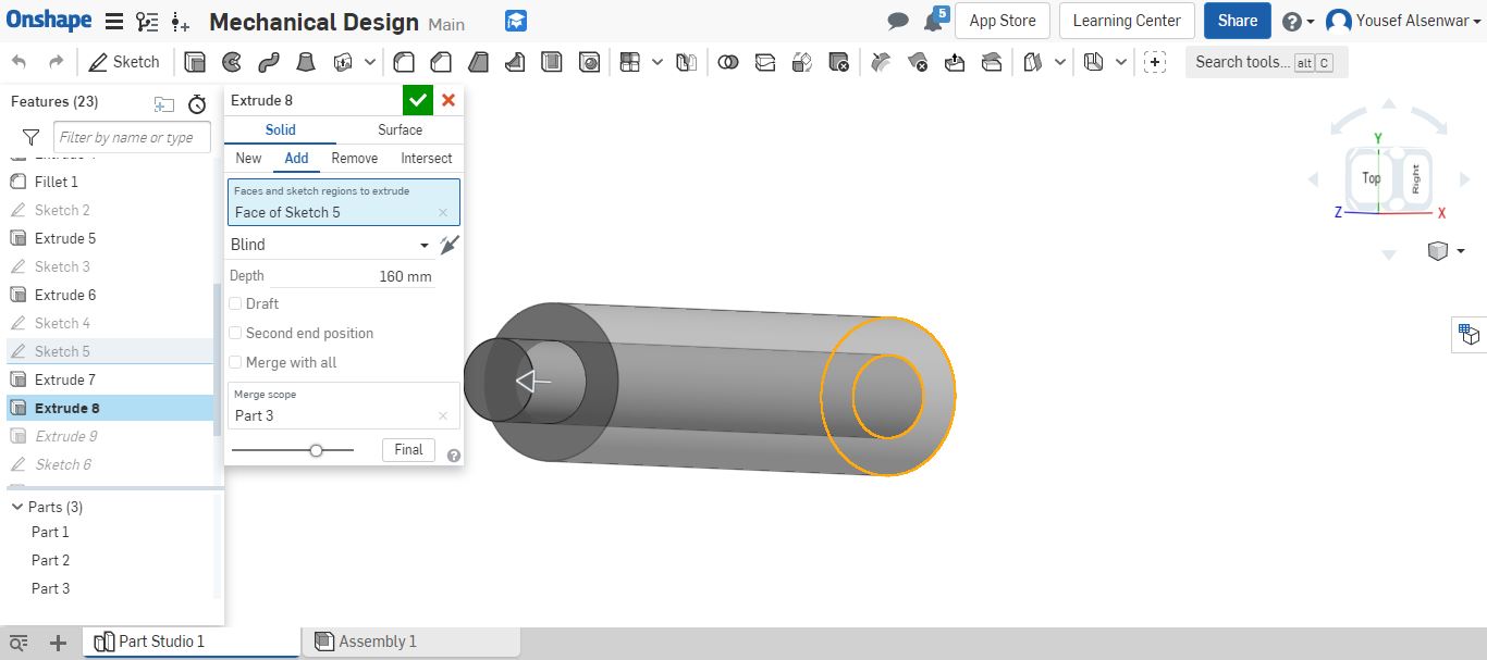
At the same direction, I extruded the outer circle by 160mm to keep 25mm of the inner circle to fit the bearing
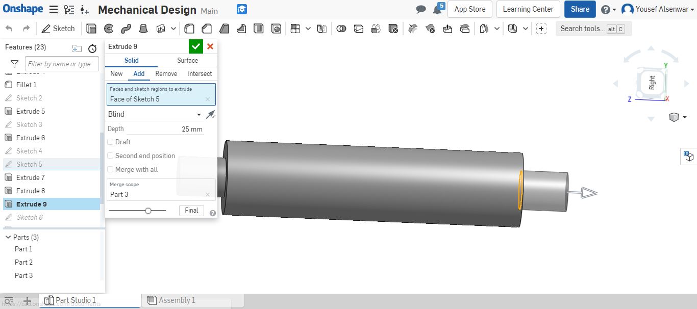
From the opposite direction, I extruded the inner circle by 25mm to fit the bearing from the other direction
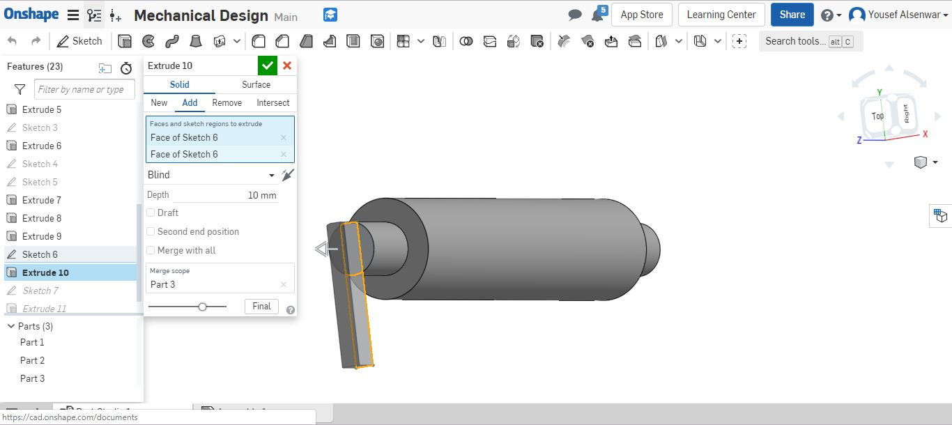
To do the hand or lever, I started a new sketch on the inner circle plane. I did simple rectangular
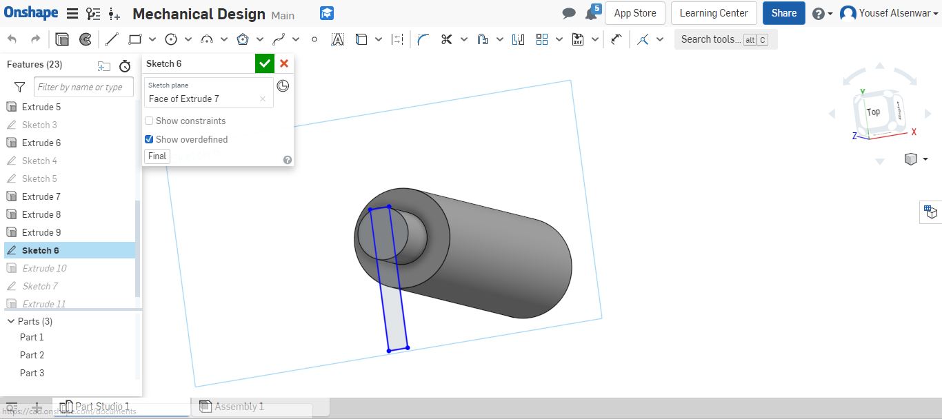
I need to extrude it by 10mm to get something like hand to move the shaft manually
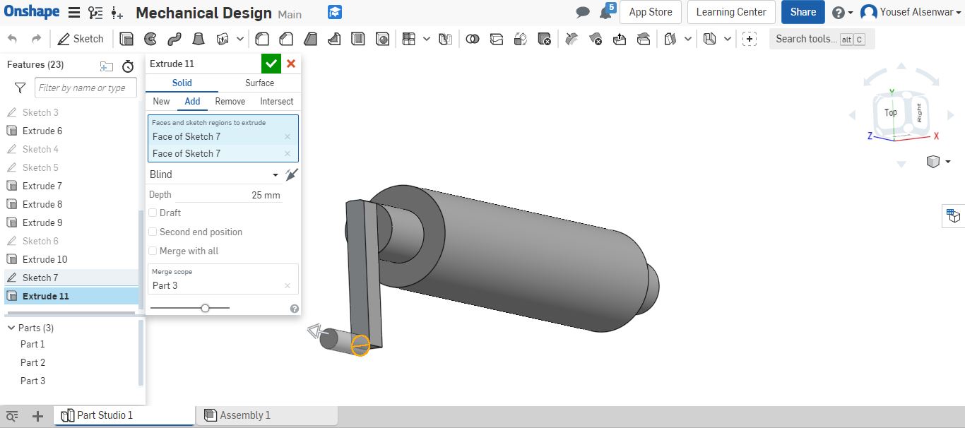
I added a simple cylinder (by sketching a circle on the hand plane and extruding it) to make the movement easier by the user
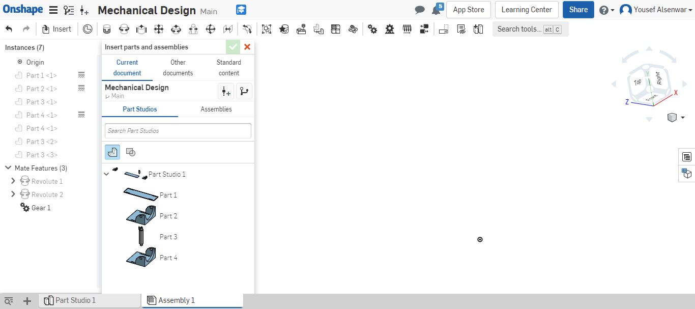
Now, I wanted to make the assembly and animate the system to check the movement. By clicking on the Assembly tab and inserting the parts
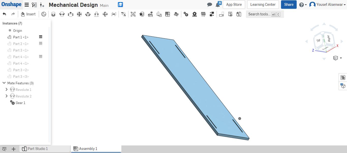
I changed the width of the base to fit two shafts to close the path of the conveyor. I placed it first to complete fixing the other parts
By using fasten tool to fix the shaft holders (which will be fixed by screws after printing the parts)
I used revolute tool to fix and move the shafts with lever
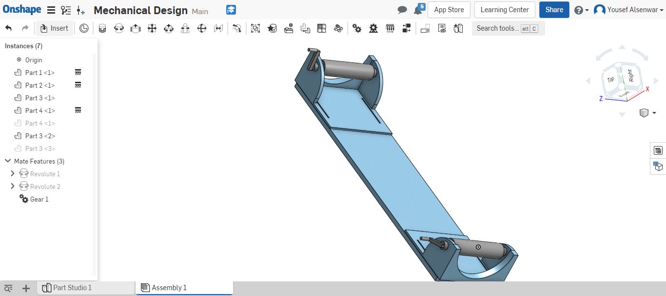
Then I did a relation between the two shafts with gear relation, to move anyone and the other one should move accordingly. Finally, I fixed all parts except the shafts to try the movement
By using Camtasia to record the screen while moving one shaft
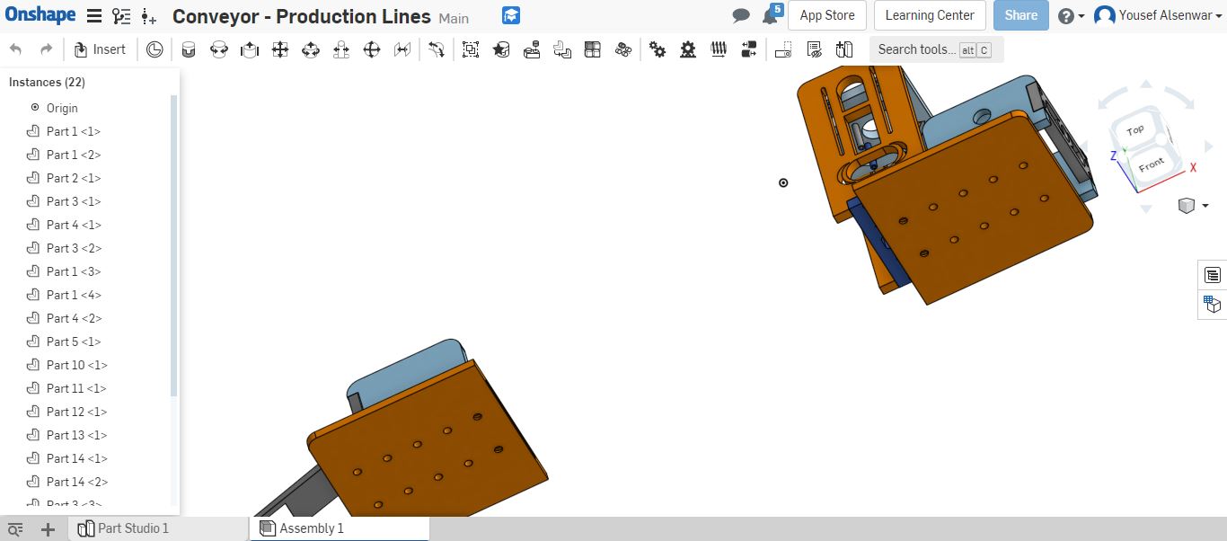
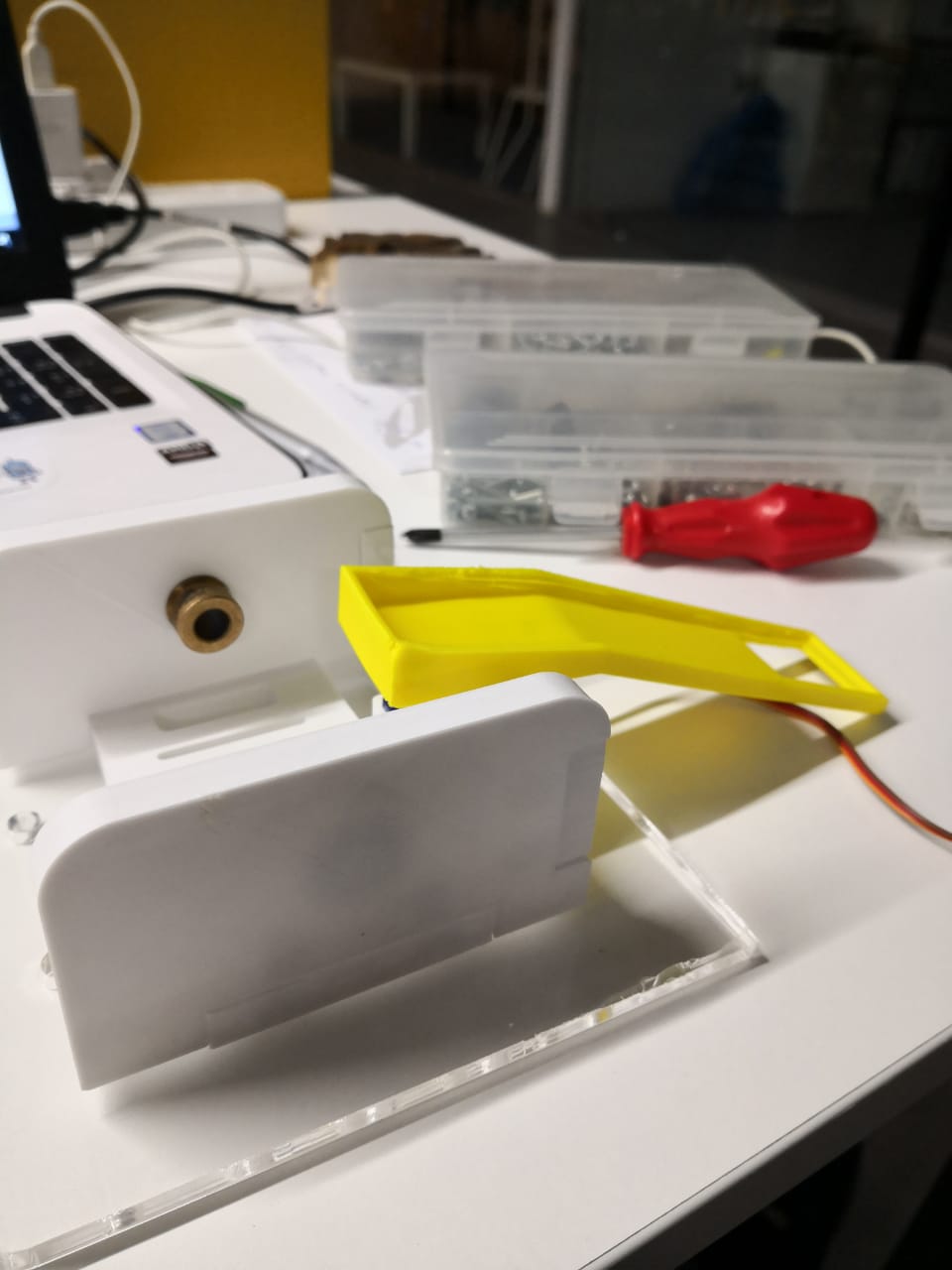
now , we held another meeting as this should be group work, Each one of us showed what have done and sharing the thoughts. We started collecting the ideas to agree on a good one to start printing and move the system manually. We collected our ideas in one onshape document and assembled them to get the final form includes a servo holder where the machine splits the output using different containers to get different colors and achieve the goal (color sorting machine)
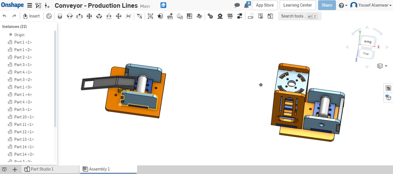
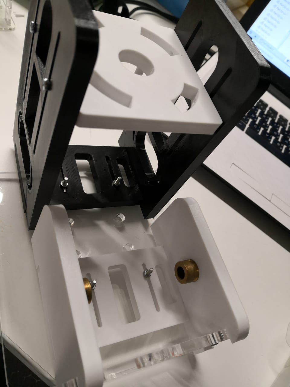
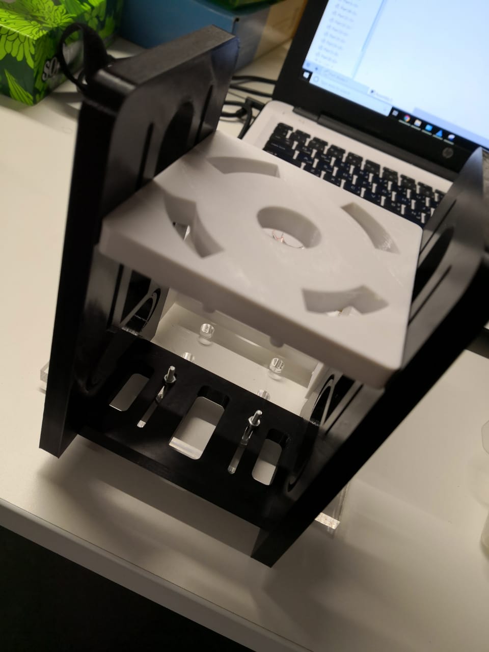
And from the bottom where we can fix the two models to connect the belt with different belt sizes
We started printing and fixing process (using 2.5mm screws) to make sure that the structure is stable and the movement is smooth
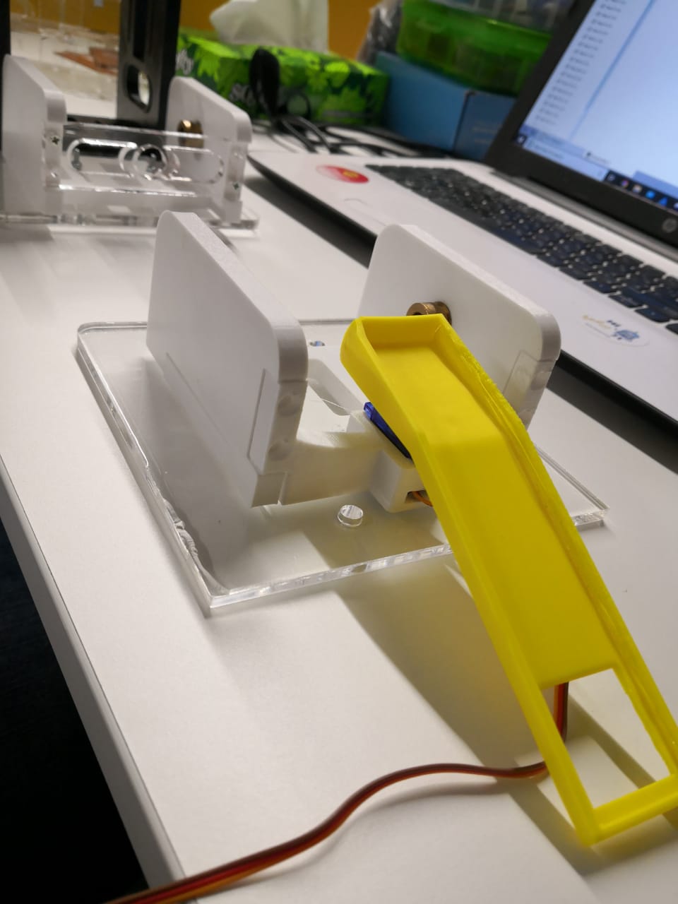

After fixing the parts, I moved the mechanism manually
Download Files' Links: