Final Project
Final Project Documentation
I decided to design this kit as a tool for people to learn about digital fabrication, and have an outcome which could be use to make any class fun. It’s a great tool for any teacher to gamify a courses, as the riddles can be personalized to ask questions regarding any topic.
In my work I manage and coordinate many spaces like Makerspaces, Fablabs, Museums and more, so this is a great tool for a fun workshop to learn about “almost anything” using digital fabrication.
Most of the 2d Design was made in AutoCAD or Inkscape, the 3d Designs were made either in Solidworks or Inventor, and PCB were made in Eagle.Coding in Arduino IDE and simulated in ThinkerCAD.
.
Also, as it is an open source project, you can MAKE it in your classroom to learn about digital fabrication, from 2d/3d design, laser cutting, 3D printing, CNC machining, vinyl cutting, and PCB production and electronics design
My greatest challange was soldering, as electronics was new for me and I had to practice a lot until I learned.

This page will explain all the process to create my digital fabricated escape room. I will explain puzzle by puzzle from design to construction, and then explain how the game itself works.
The Video for The final project
Also, Here Im adding the process of this kit and tools used as a one kit for teacher as i explained earlier
Components and tools
- Bottle Lock. This device will be designed in CAD and 3d printed. This will help have a clue locked, and only until they find the solution they can take it out of the bottle.
.jpeg)
- LDR/Laser Code Machine. This box will be designed in CAD for laser cutting, and the electronics will be manufactured and created from scratch. The idea is to have 4 different LDRs, and when target with a laser which each team needs to find (and batteries are also hidden in the room) then will display a code for them to find the next clue.
.jpeg)
3. Iris Mechanism with lock. This puzzle will also be laser cutted or cnc machined, and will be used to keep a clue locked until they can find the solution to a previous task
. .jpeg)
4. Paper Lock. Laser cut. Also used for keeping clues locked

5. Double Spinning wheel mechanism. This one will be cnc routed. Its a double spinning wheel mechanism used thank when placed in the correct position will show the code to unlock a puzzle. It will have a bearing for easier rotation, and the numbers will be embossed in the surface.
.jpeg)
Now i will explain each one :
IRIS MECHANISM
To begin, I will start with the Iris mechanism. The Idea of this mechanism is to create a mechanism to keep a clue locked, and only when the participants decipher a code, they can take the lock of, operate the mechanism, and find the new clue. This puzzle required 2D CAD, which was done in AutoCAD, 3D modelling, Assembly and simulation, which was done in Solid works, and laser cutting for Fabrication.
For design, I began with the static base. For this, I draw a circle with the radius of the size I needed, then a smaller circle outside for the handle, and connect them with straight lines. Then, trimmed the unwanted lines, added some fillets and a smaller circle for the lock to go in.

Next, I will draw an inner circle which will be the part of the iris to open and close. For the links, I will draw two circles 10mm from the inner and outerborder as shown below.

Next, because my mechanism will have 5 parts, I will do a polar array in order to replicate the two circles 5 times in equally distributed angles, as shown below.

With This, my First part is done. Now, I need to do the moving mechanism. For this, I will create a moving base, with the same size as the fixed one, so I copied the outer outline of the circle with the handle. After this, I created 2 circles from the center to the inner and outer diameter of the small holes closer to the outside perimeter. The idea is to put some screws in the fix based, and the moving base will slide through a slot of the same diameter in moving part. Now, I will create a copy of the circle at 35 degrees from the original, as shown below

Now, I will trim the unwanted lines to keep just the slot.

Now, I will create a circle 20mm from the outside border. Additionally, I will draw a circle in the 12mm radius circle in the projection of the midpoint of the slot in the circle we just created, and a small circle in the space created, as shown below, and then, trim the unwanted lines.


Now, I will create the link, whichi will just be repeating the same steps for the slot, but with 70 and 60 mm radius circles for the inner and outer profile, and 5mm circles 45 degrees apart for limits, as shown below. After this, just trim and leave only a single link, and draw a 5mm diameter circle in each corner, and change layer and color to indicate a new part.


Now, we need to draw the closing parts. For this, I will copy the inner circle from the fixed part, and draw two lines at 75 degrees, as shown below. Then, I will create two arcs, from the center of the big circle to the point where the lines intersect the circle, as shown below, like drawing a shark tooth.

Now, I will create an offset of the circle at 12mm, and then extend the arcs until this circle, as shown below. After this, I will just trim the outside and leave the tooth, as shown, and finally, just add 5mm fillets on the sharp corners.


Now, we just need 2 circles for pivot, as shown below

Now, I will put the link and closing part in the center of the moving part, to then create a polar array of 5 instances, as shown below.


Now, just trim the small line between the 12mm radius circle and second perimeter circle, as shown below, and the design is done.

LINK TO VIDEO IRIS DESIGN.
To download the Design Press Here: Iris
Now we need to laser cut and assemble. For assembly, I will take the drawing to a 3d CAD software and simulate its operation. For this, I just import the DXF into solid works, and extrude each part in a different file. Then, create a new assembly and the first step is to find the base

Then, place the movable part on top, and use m3 screws between the slots of the movable part and the 5 holes in the base (highlighted in blue), and use a nut to secure on the other side. Make sure the head is on the top of the movable base.

Now, find one of the closing parts, and place it on top of the base as shown. Use a m3 screw and a nut to fix in place as shown.

Now, get a link, and use 2 m3 screw to fix it on one side to the movable part, and on the other side to the closing part.

Repeat this 5 times for all the sides, and your iris is assembled.

Download 3d Files: 3dfiles
Bottle Lock
The idea behind this puzzle, is to keep a clue safe, being locked inside a bottle. A bottle will be hidden in the room and identified for each team, and to open the lock, they need to solve the clue. This puzzle will make us of 3d design and 3d printing. For designing, I used Inventor. Because it is a moving part, I design the assembly as a part, but in two separate bodies, leaving the tolerances for it to move.
In the video, you can see the process of how it was created.
The most important part was after finishing the first half, when I created the operation of the other side of the hinge, you have to create the extrude operation as a new Solid.

Also, this design is parametric, so if you have a different bottle and need to change its design, you can just update the parameters, export the stl, and print. To make this easier , I created a form with the parameters I want the user to control, and when the form is changed, it updates the parameter which controls the dimention of the solid.


As Shown below, by just changing the parameters in the form, the solid updates, and the user just needs to export again as stl, and send to print.


Download File: Bottlelock
CodeBox
The codebox is a simple and easy tool for keeping codes safe. This puzzle requires only 2d design and laser cutting. For 2d design I used AutoCAD, and it was cut with a laser cutter using MDF wood.
The following image shows the parts of the puzzle, and the instructions for assembly are the following

Laser cut and fabricate all parts 1,2,4, and 5 in 3mm non translucent acrylic or wood.
Laser cut part 3 in 1mm or thinner material.
Paste part 2 over part 1.
Paste part 3 over part 2
Paste part 4.
Part 5 should be able to slide inside and once in place, can be locked so it cannot be taken out.
Once assembled, the clue can be hidden and locked inside, and once open, you can read the code, as shown below.


The codeBox video
Download File: CodeBox
LDR BOX
This is the main component of the escape room. It integrates 2d and 3d design, laser cutting, vinyl cutting, pcb design and manufacture, and input and output devices. The design of the board was based in Danielle Ingrasia Satcha Kit, but modified to have my desired input and outputs, as explained in the Input and Output weeks.
For creating the box to hold everything, I created a tabbed box using inskscape, and then used autocad to add the holes for the on off button, LCD screen, LDRS, and for easier assembly.
Download File: ldrdesign
After designed, I cut it and assembled it.
VIDEO LDR BOX ASSEMBLY
I used Eagle to Design my PCB board, using at atmega 328as a microprocessor.
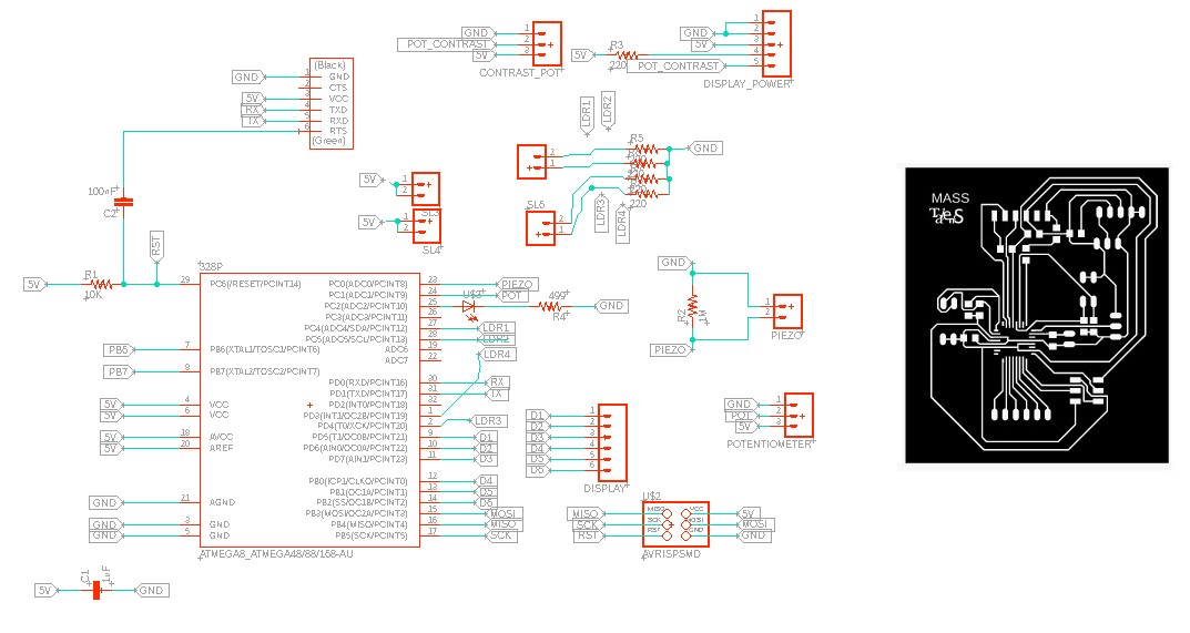
Download File for the PCB: PCB_Design
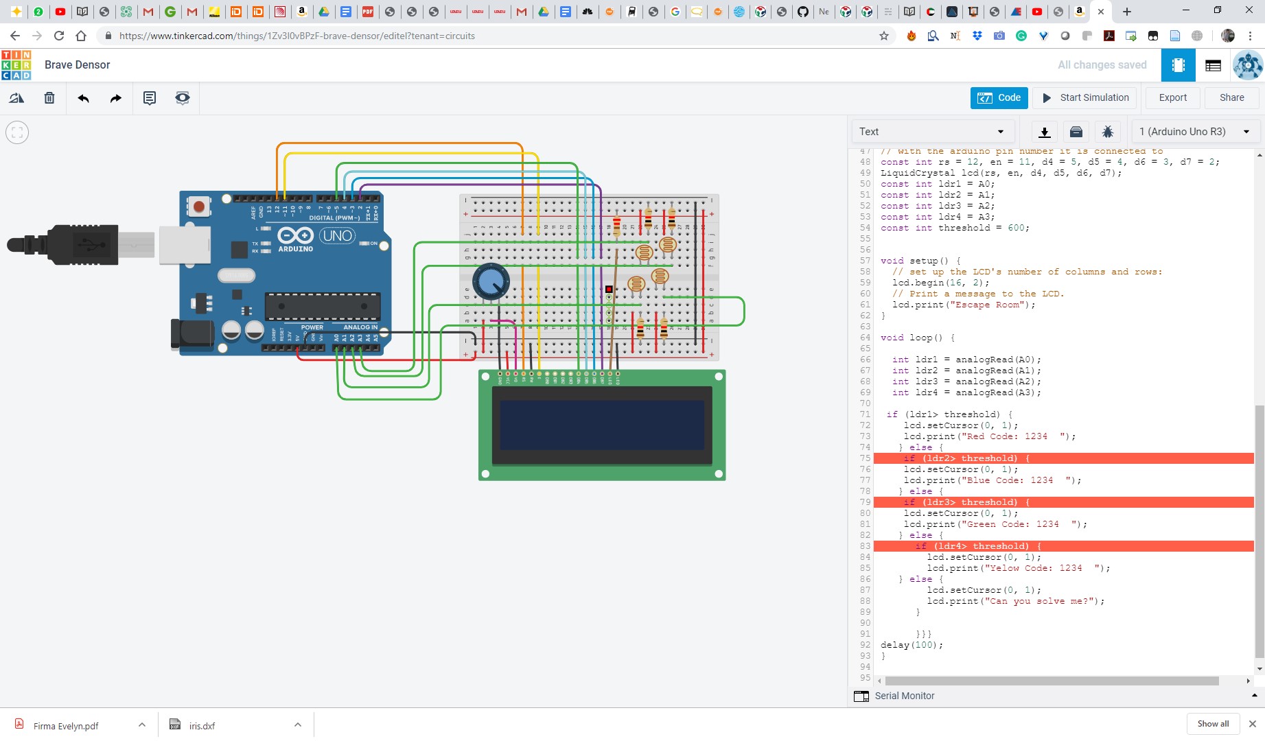
The code used for this created using arduino ide. I started based on the Liquid Crystal Library Hello World Example, added 18 Apr 2008 by David A. Mellis, modified 5 Jul 2009 by Limor Fried, and the example added 9 Jul 2009 by Tom Igoe and modified 7 Nov 2016 by Arturo Guadalupi. I began by modifying the pins to adjust to the ones available in my display, Then I created the logic to evaluate the status of the LDR inputs, and then according to this, display the messages needed on the screen.

Download File : The_code
After designed, I simulated the functionality and the code using the simulation.
And then fabricated the board, but had a lot of trouble because the cooper was old and had absorded himidity, and also the bits where not sharp.


I ordered new cooper and bits, and after this, the board was able to manufacture successfully, and then the soldering process was very tough. I tried to solder more than 10 boards until I finally got one to work.
Electronics Assembly video
LCD Assembley
 /
/
Then for the inputs, I connected my LDRs to the pins I created. Beca*/]=7use I was learning, I wanted to see the difference between analog and digital, so two of the LDRs are connected to a Digital Pin, and 2 are connected to an Analogue pin. This is the reason why in my code, LDR1 and LDR3 are evaluated by comparing to a threshold value, while LDR3 and LDR4 are just compared to HIGH.

After connecting, I begin testing, and I was very happy when finally LCD finally shown the initial message!

Then I connected my LDR’s and begun testing, and had to reprogram my threshold until It managed to work. Also, I had a mistake regarding the pin numbers used for the analog inputs, as I was naming the pins on the atmega, but I just had to use the Analogue input number from Arduino. After fixing this, the LDR BOX finally worked.
LDR Testing Video
Double Spinning Wheel
The double spinning wheel is a puzzle that integrates 2d design, CNC machining, and laser engraving. I started by making the 2d design in Autocad.

Download File : double_spinning-Design
Then I manufacture the parts in CNC and included pockets for the bearing. And then engraved the divisions and numbers using a laser cutter.


VIDEO Double Spinning Wheel.
Final shape

DIY Laser
The DIY laser is a puzzle that includes 3D modelling, 3D printing, and input and output devices. This includes a laser as an output and a push button as an input. For this, I created a 3d model, to fit all the parts, with a snap fit mechanism to keep all the elements in place.
Download File : LaserCase
Then I 3d printed and assembled all the components, and test it
And finally used it with the LDR box.
After finishing all the puzzles, the BOM of my project is shown below:

as shown, for less than 120 USD, you can create your own digital fabrication escape room, to enable any teacher to gamify their courses, as the riddles can be personalized to ask questions regarding any topic. Also, as it is an open source project, you can MAKE it in your classroom to learn about digital fabrication, from 2d/3d design, laser cutting, 3D printing, CNC machining, vinyl cutting, and PCB production and electronics design.