ElEctronics Production
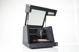
For this week, my labmates used the MDX-20 and fabmodules. To try something different, I decided I was going to use our new carvey CNC machine.
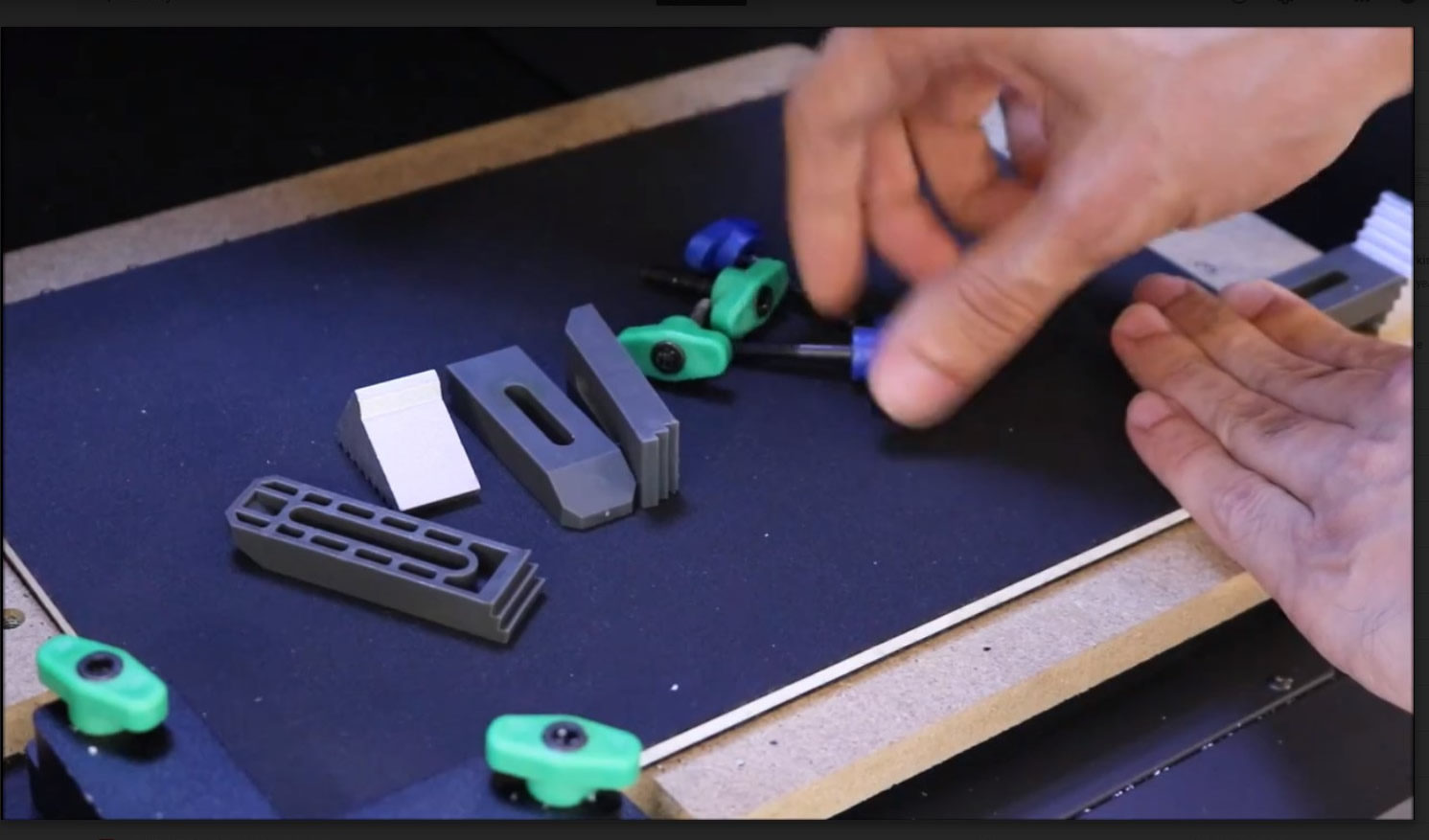
The first step is to secure the stock into the machine. For this, you normally use double sided tape, but this machine has a very nice set of clamps that are provided in order to make sure that the stock is strongly secured to the machine.
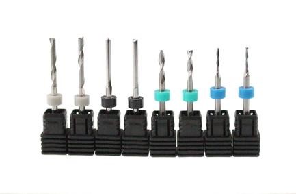
After checking the design to mill, I saw the 1/64th but was appropriate for the milling, so I proceed to load this bit into the spindle mount.
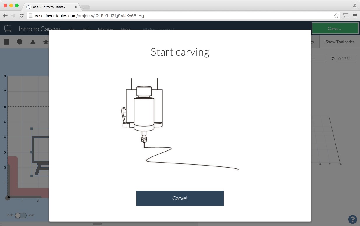
For the software, Open your browser and go to http://easel.inventables.com/carvey/ and follow the instructions that guide you through the process. If you are not registered yet, you are promted to do so:
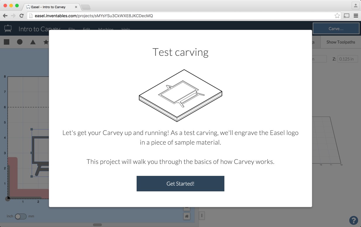
First, let’s do the test carving.
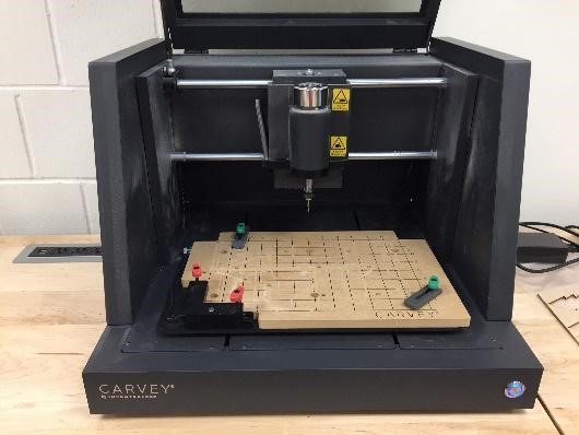
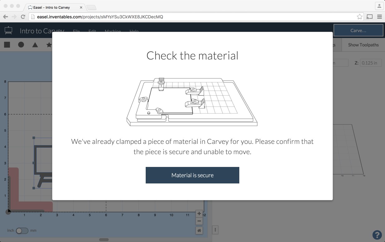
By default, there is already a sample material clamped to the base of the cnc. Verify that is in place, and retighten the clamps to make sure the material can’t move.
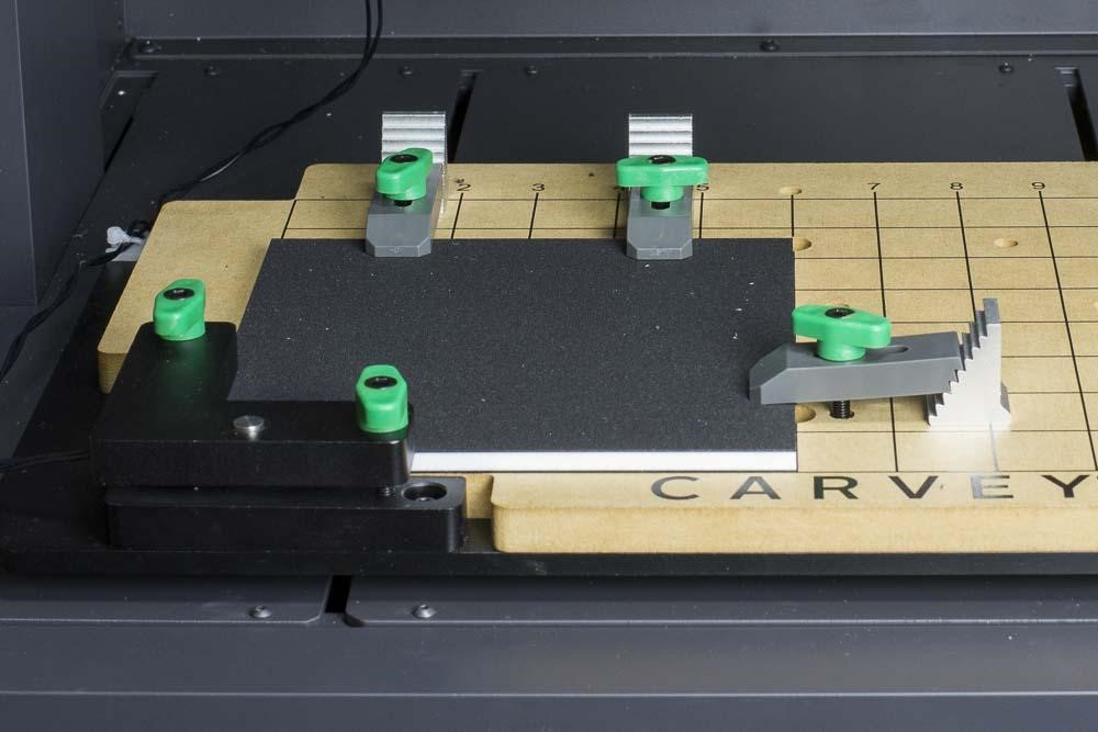
Double check that the material is clamped firmly by the Smart Clamp on the lower left corner. It should look like this:
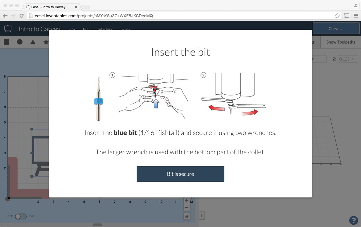
Insert the 1/16” fishtail bit into the collet and tighten the nut with the supplied 13mm and 17mm wrenches. The small wrench goes to the fixed part in the head and the bigger one to the movable nut. Tight as shown below:
Now, we can upload the design we are going to cut. For this, I can import an svg, a gcode, a dxf file or an image. Now, you need to load the actual files for the isp. This is yet another version of an AVR ISP programmer/board that can be produced in a fab lab using a milled PCB and readily available components. The project is based on the efforts of many people. For more history of the FabTinyStar and the people who have contributed to it, please refer to Zaerc's FabTinyStar page.
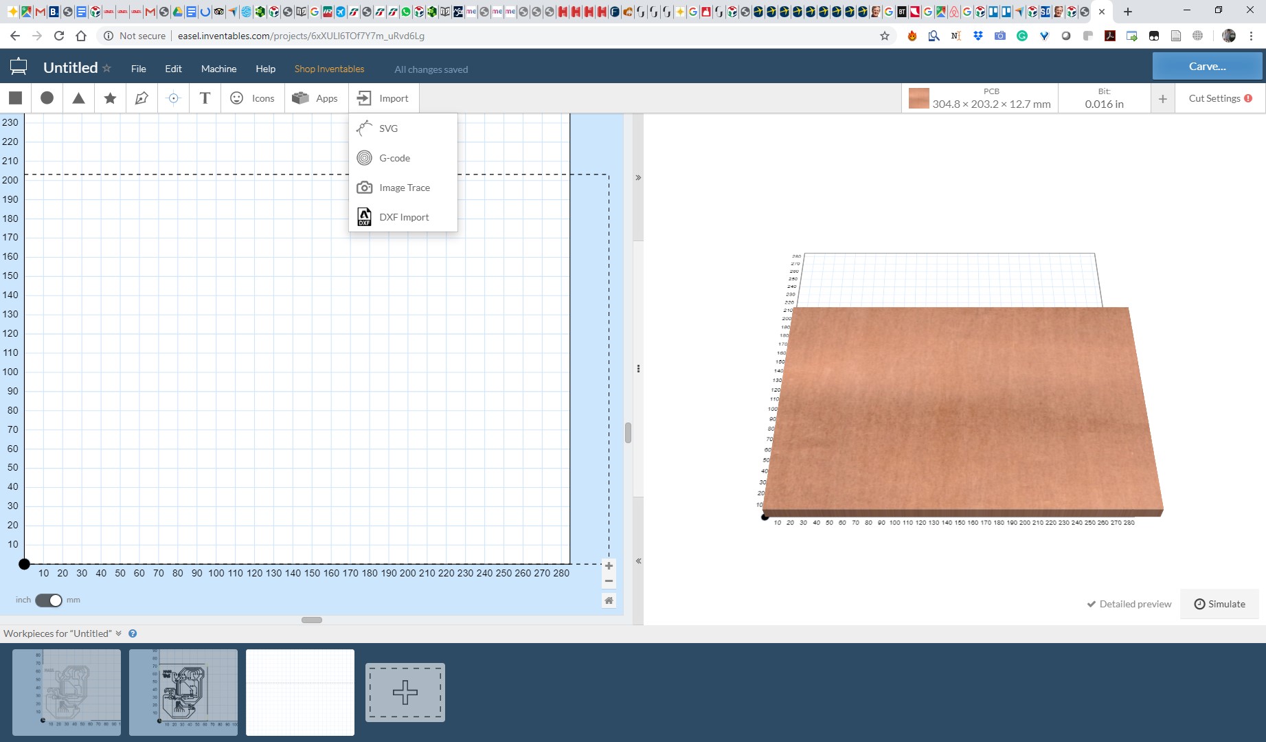
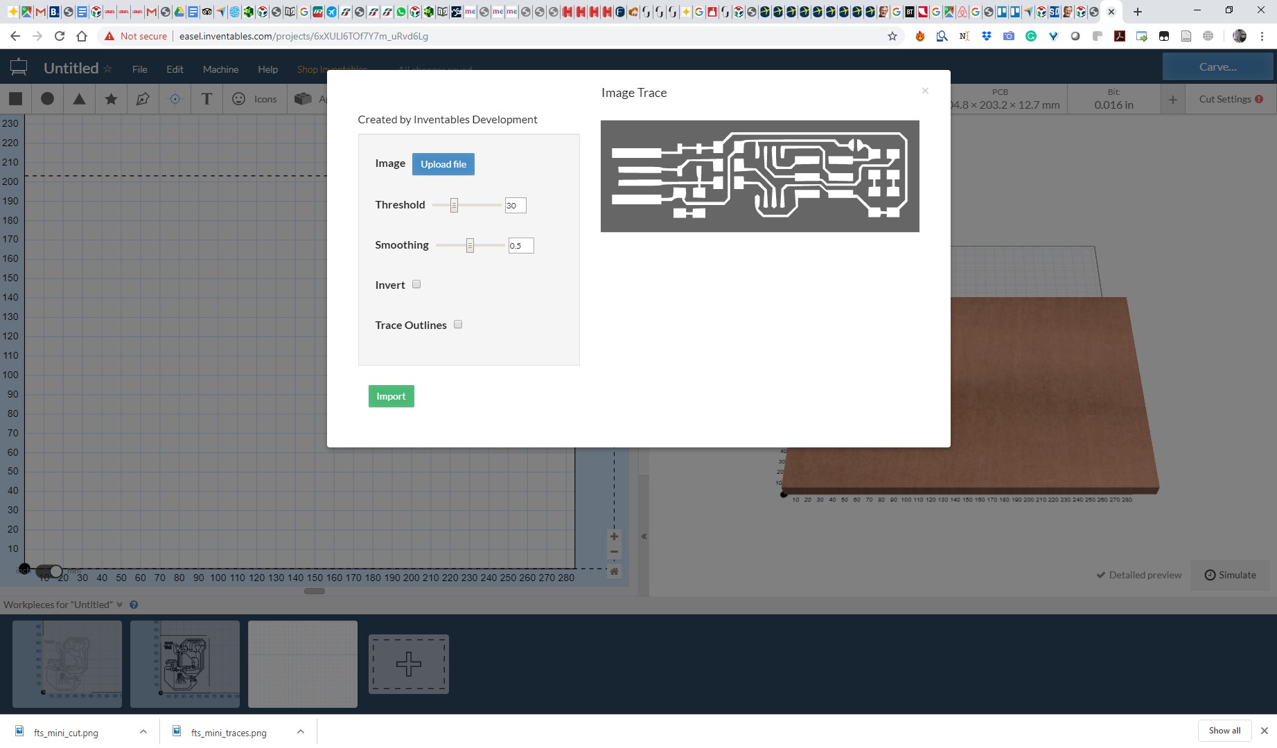
For this example, i will select image:
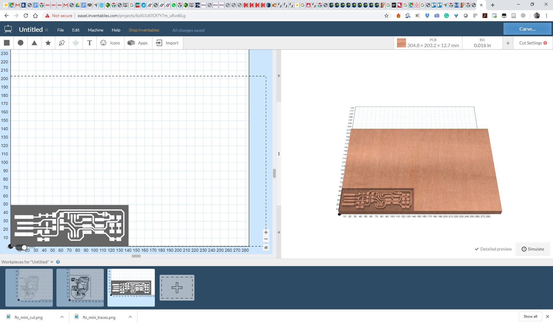
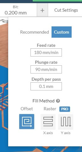
And after imported, I can select the bit and depth to carve
Before Cutting, I tried to test my machine with different feed rates and spindle speeds to test which combination gave us the best result.
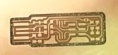
When Using a high feed rate, and slow spindle speed, the traces are very rough and the copper seems to be pulled away and not cut, and the results are very bad.
When I start decreasing the feedrate and testing different spindle speeds, the results begin to get better,
And the best results where obtained by using a 3mm/s feed rate, a 1.5mm/s for the Z axis, and a 0.1mm per pass.
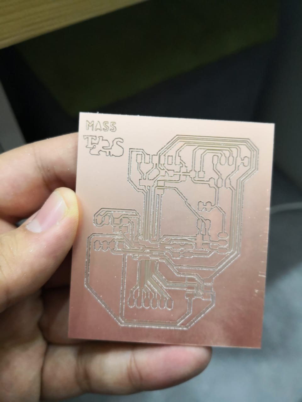
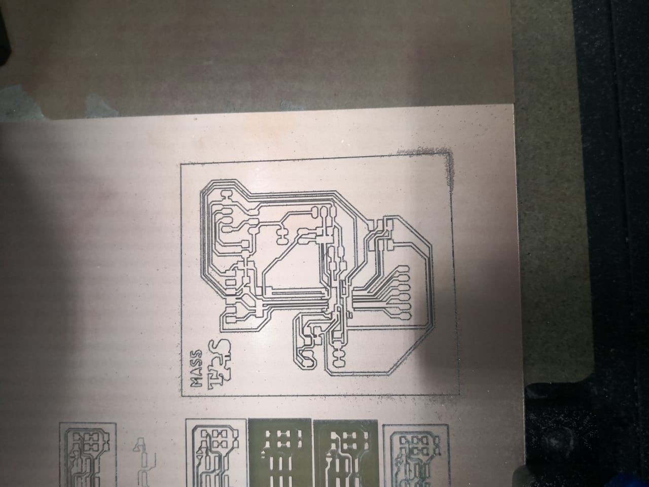
The traces, are to be cut using the 1/64 inch bit, but for the cut layout, we can use the 1/32”. The final result was pretty good, and the part is now ready for soldering.
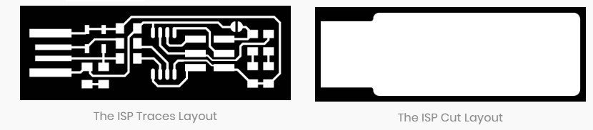
The traces, are to be cut using the 1/64 inch bit, but for the vut layout, we can use the 1/32”. The final result was pretty good, and the part is now ready for soldering.
After the job is complete you can open your Carvey and remove the material.
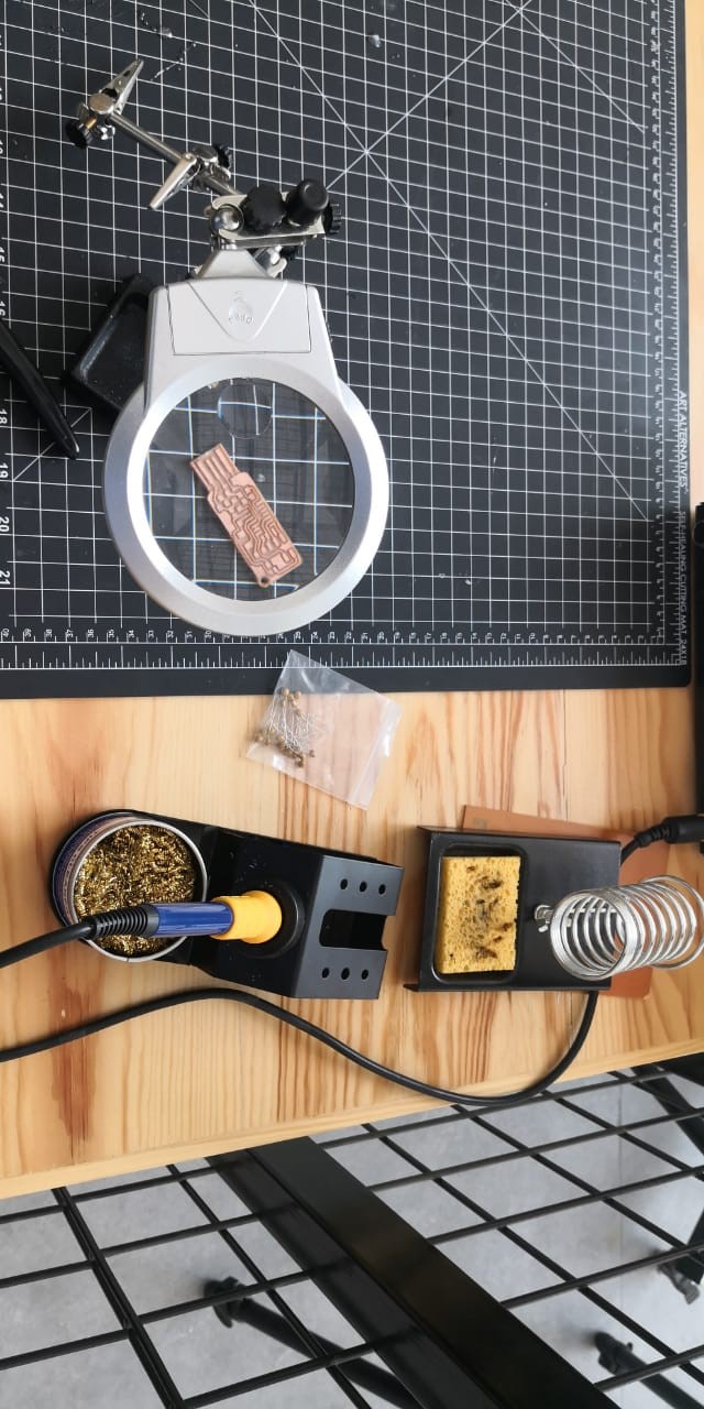
Soldering was a really difficult part. i had to try a lot of times because my skills where not the best, but after a lot of practice. This was the setup I used for soldering
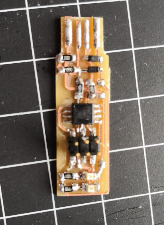
And after several attempts, this was my best result(which I know can still be improved, but im very proud because I did it myself)
I followed the steps in the tutorial for programming the ISP, and with my instructor's help, I was able to program the ISP correctly. When connected, the led was working
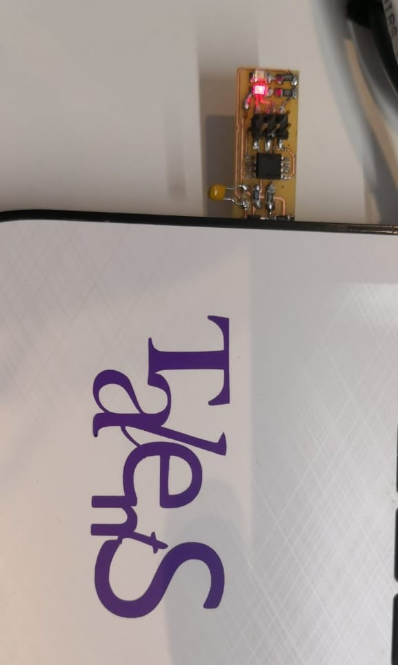
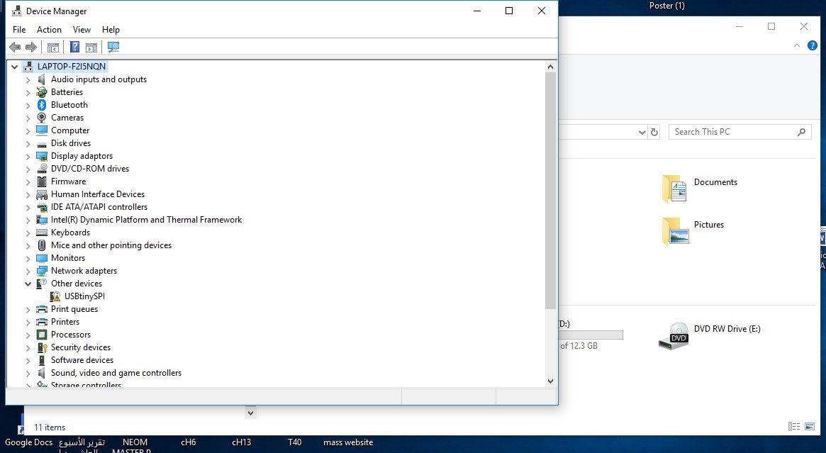
But it was not recognized by the pc.
But it was not recognized by the pc.
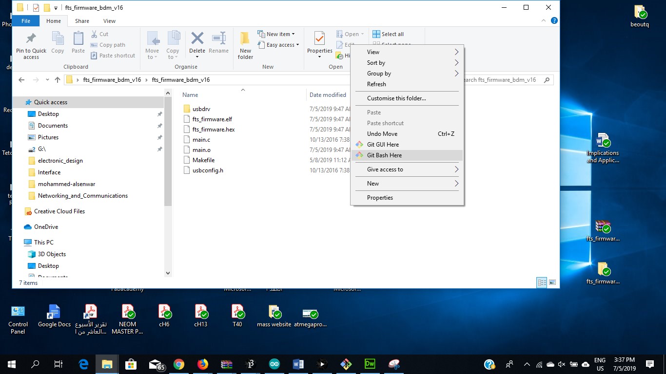
So, I followed the tutorial on http://fab.cba.mit.edu/classes/863.16/doc/projects/ftsmin/index.html to install the firmware.
Download File : Firmware
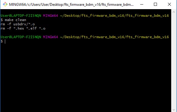
unzip the firmwere and put it in the desktop and open git bash fron the file
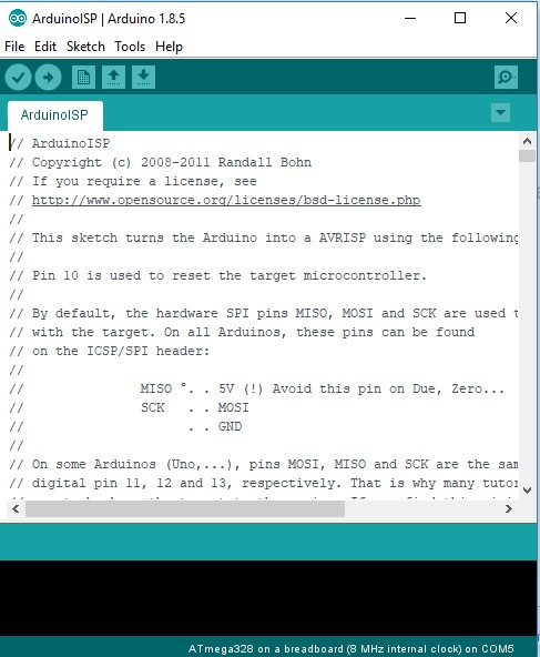
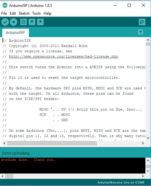
Now should I connect Arduino uno and I have to upload Arduino isp on it
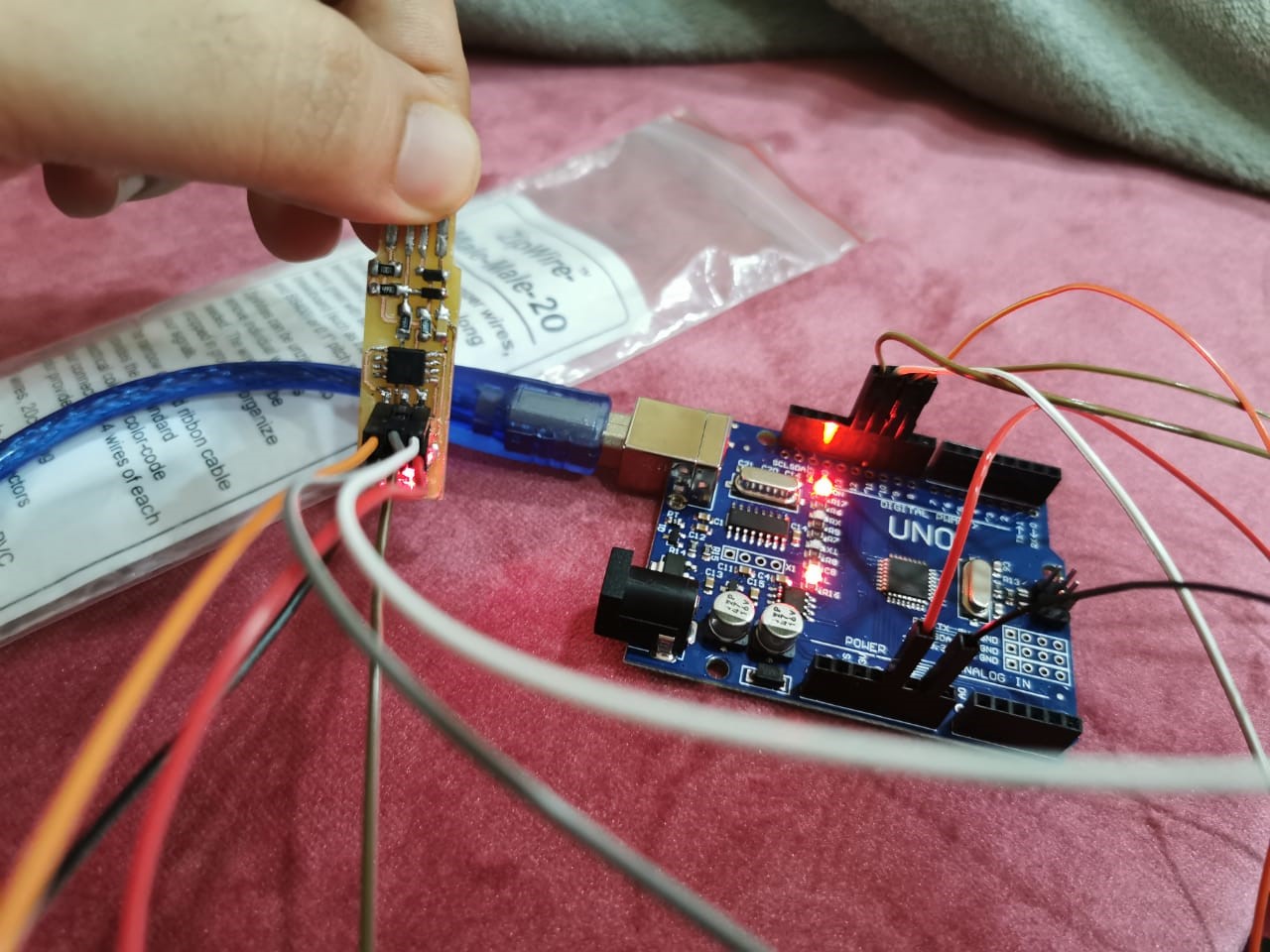
Now I connect the ISP 6 pins to Arduino
ISP pins |
Arduino pins |
6 GND |
GND |
2 prog |
5v |
1 Miso |
12 |
3 SCK |
13 |
4 MOSI |
11 |
5 RST |
10 |
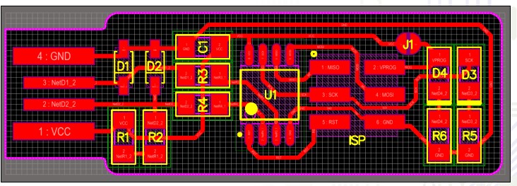
Using the following schematic
Now connect the Arduino with the laptop
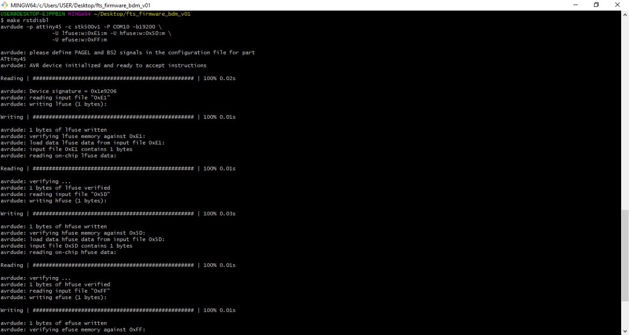
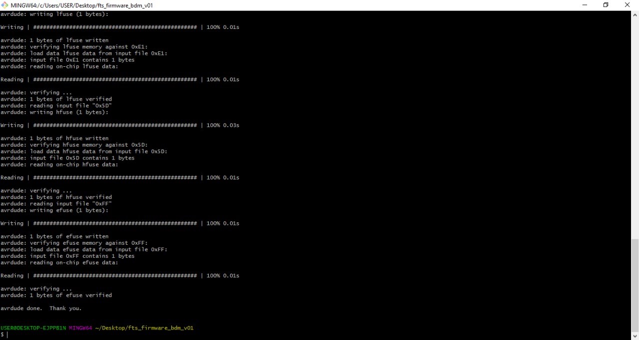
Start with (Make clean) command
Then ( make ) Then (make flash) then (make fuses) then (make rstdisbl)
.jpeg)
The file I used was add.hex file
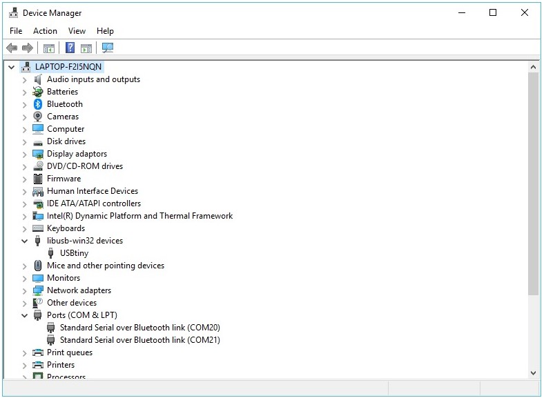
and finally, when connected to the PC, it was recognized!!
Explain ISP video with our local mentor : Daniel