Computer Controlled Machining
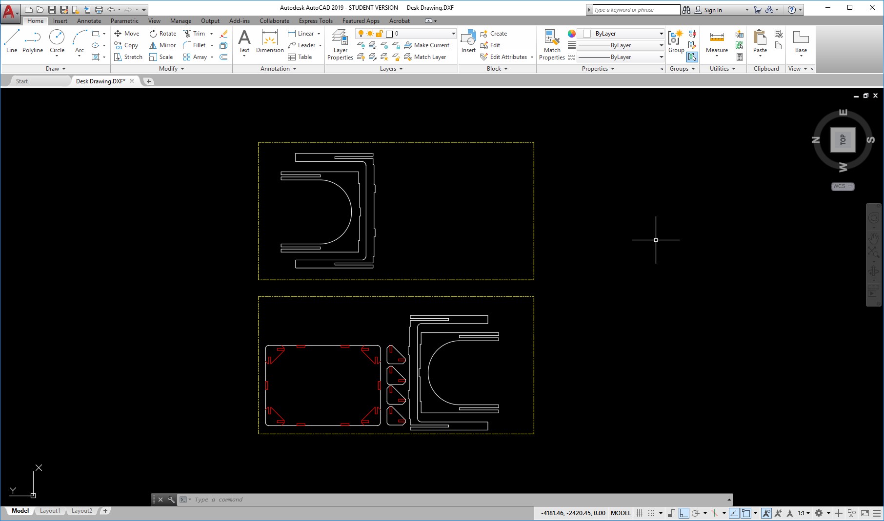
For this week, Im finally making my real size desk for my project. For this I started drawing in AutoCAD because Ive used it before and its just faster for me. I want my desk to be 100 cm x 60 cm, so I begun from a rectangle that side, and then design the legs in order to be able to intersect between each other to give them stability. I also designed a joint support to hold the pieces in place.
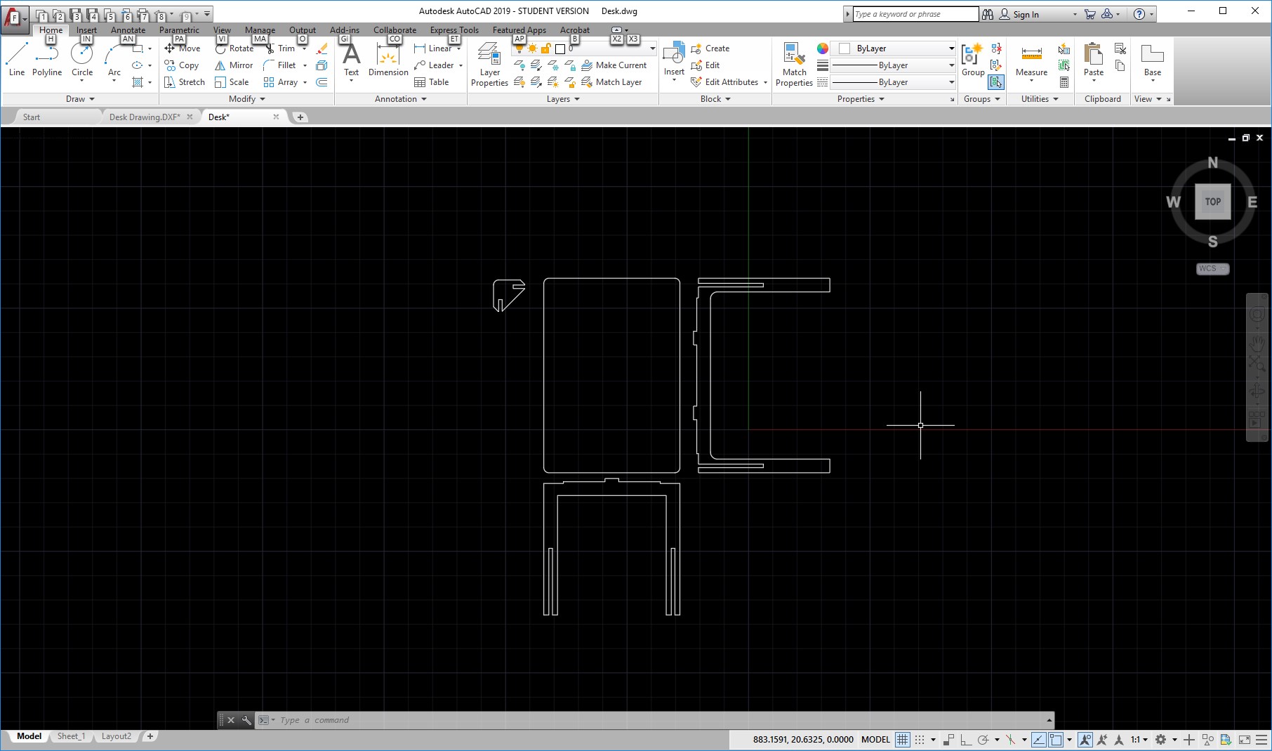
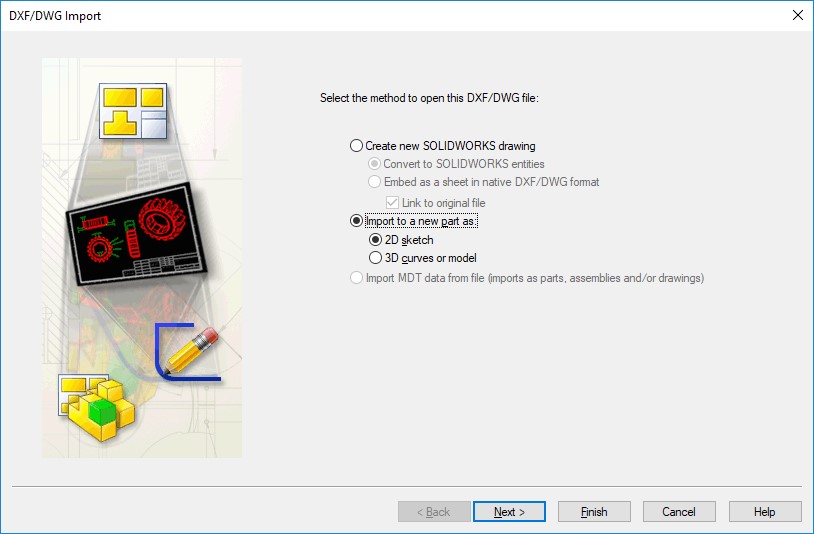
After I have the basic idea, I wanted now to verify it in a 3d environment. Autocad is very good for 2d, but not enough for 3d, so I just saved my file as a DXF and then went to Solidworks. There, in the open dialog, you can change the setings to all files and select DXF. In the following pop up screen, select the import to a new part option, and make it a 2d sketch.
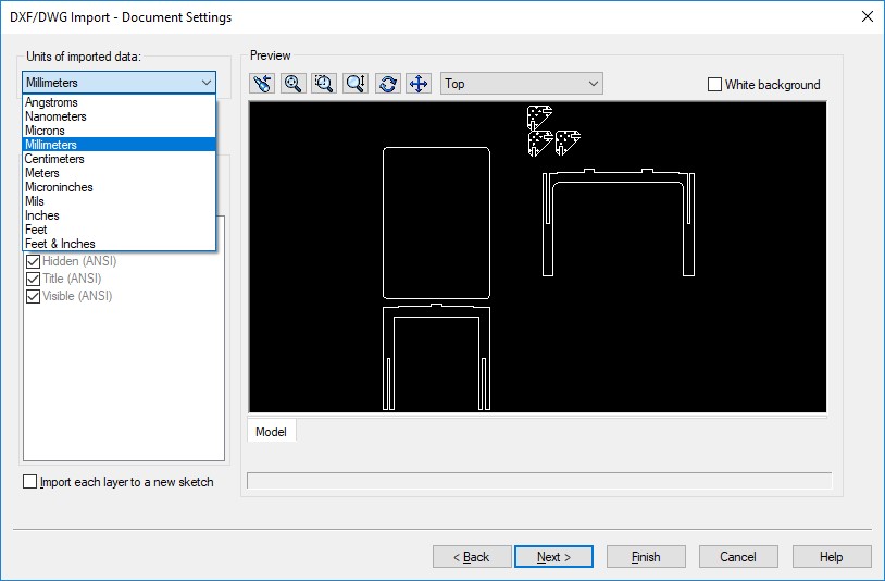
Click next and make sure you change the units to the same ones you had designed before. In my case, I used millimeters. Click next and then finish.
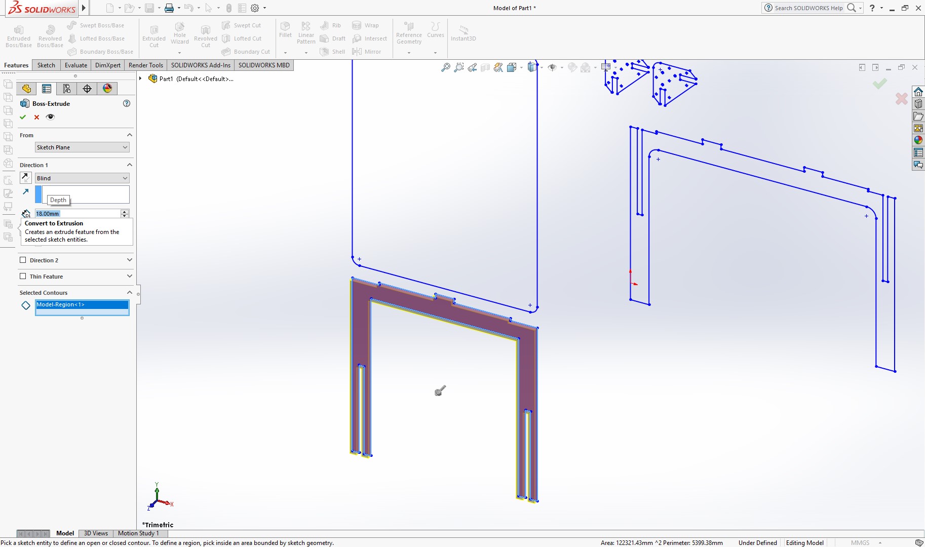
Your drawing is now a sketch in a new part, so you can easily extrude them and save them as part. Repeat this process for each of the parts, so you will end up with 4 files, the top surface, the side leg, the front leg, and the joint.
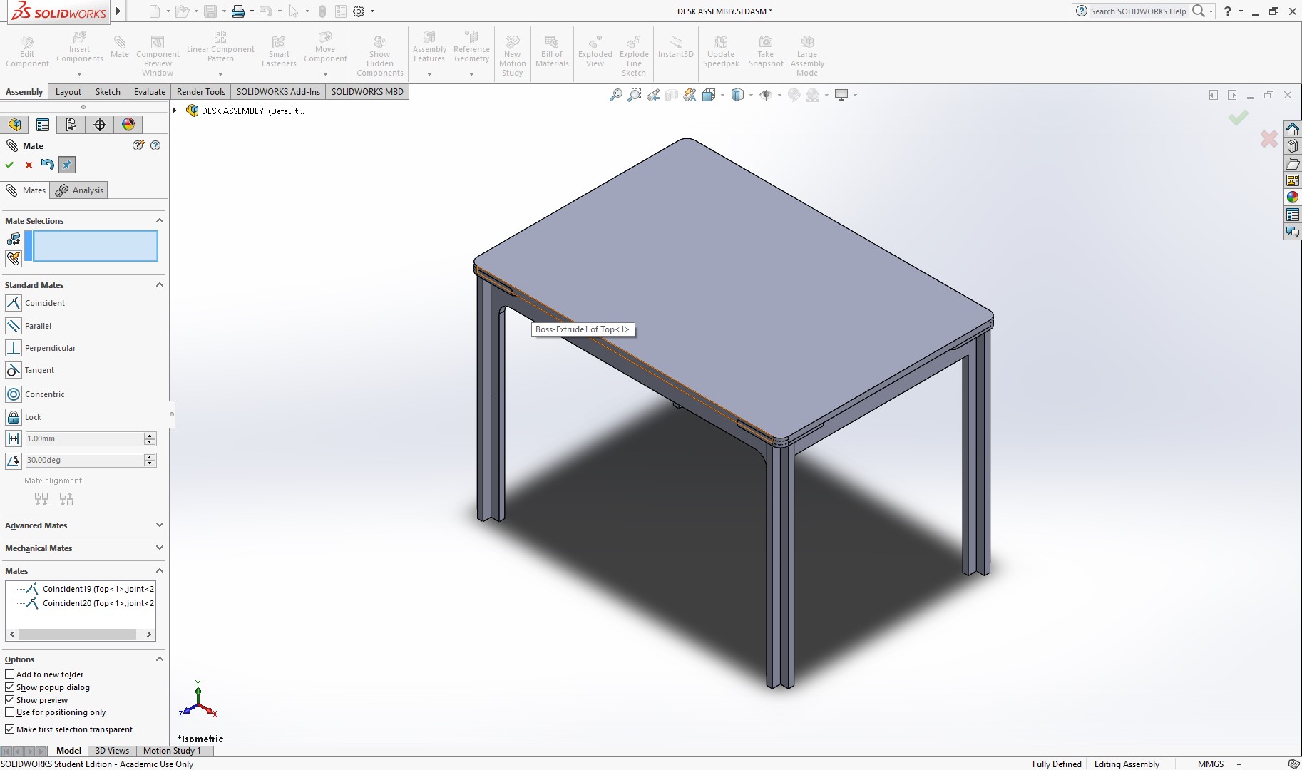
Now, create an assembly and place the 4 parts, and remember you will need 4 joint, and 2 of each legs, so 9 parts in total. Then, use the joints to assemble the desk as you would do in real life, and verify if this is working correctly.
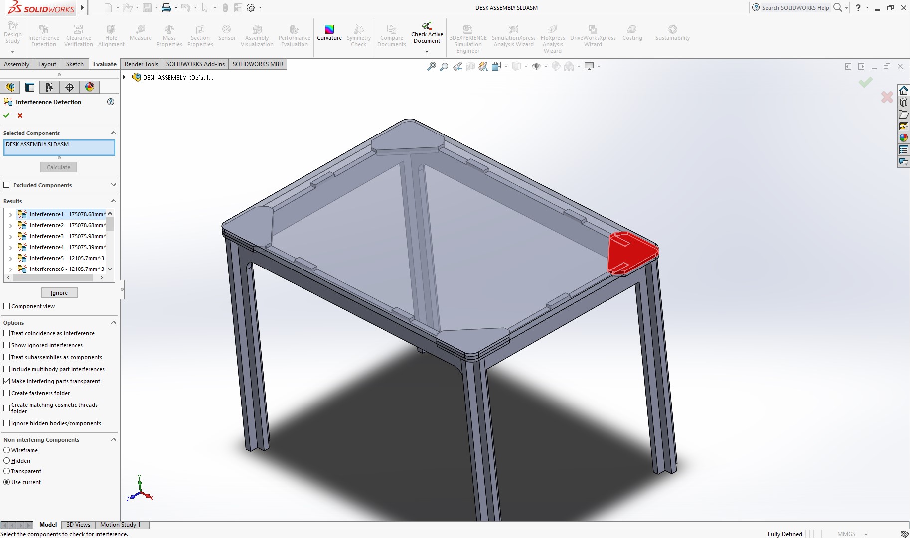
Now, go to the “Evaluate” toolbar and select the detect interference option. As expected, the table surface parts is intersecting with the joints and the tabs for each leg. But overall, the assembly looks good as expected.
This mean I can go back to my 2d file, and organize it for CNC machining. For this, the first thing is to draw the area of the material sheets, which are 1200mm x 2400mm. Then, I will create 3 layers, one for indicating the material sheets, one for the cuts, and one for the pockets.
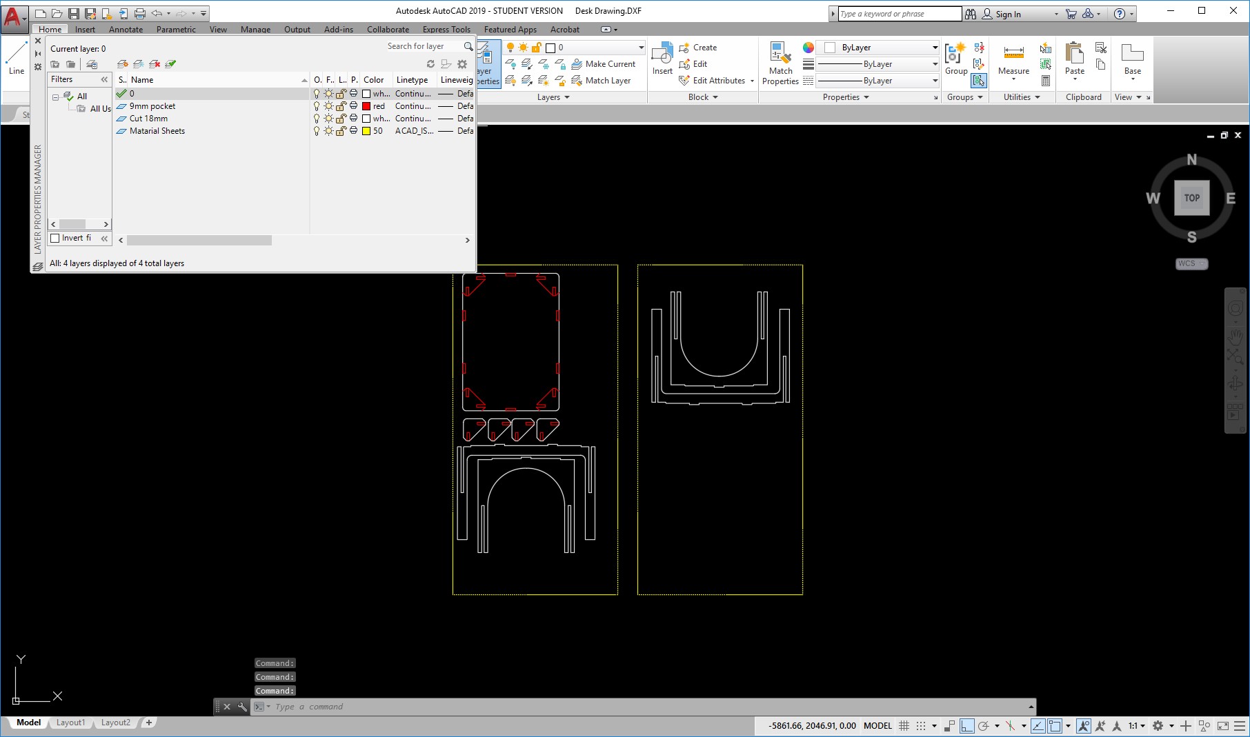
The stock will be 18mm thick, so I will make the pockets half the size. Also, for the tolerances, I will make the pockets a little bigger to make sure they fit.
I focused in the table surface area to design the pockets that were causing the interferences.
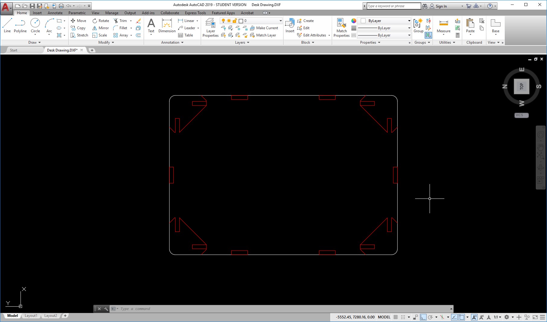
I added pockets to the joints also so that the height of the table would be as desired. The final distribution looks like this.
Now, I will arrange them for cutting using the machine software which is Vectric. I import my DXF and arrange the files. I will use a 6mm spindle, the cuts will be 18mm deep and and pockets 9mm. When cutting, I can add some tabs to prevent the loose parts to move once they are cut.
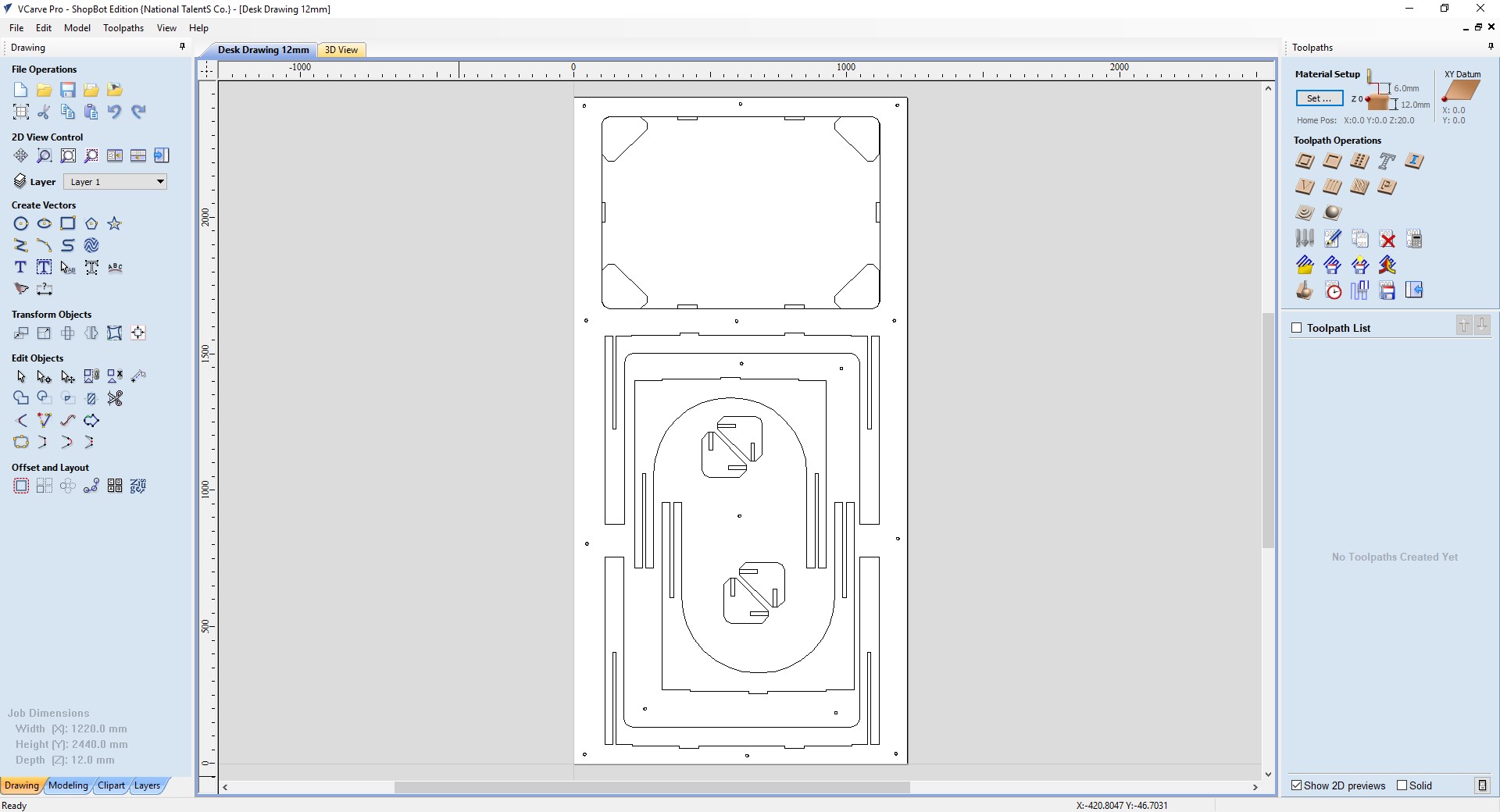
After opening the file, the first step is to import my file.
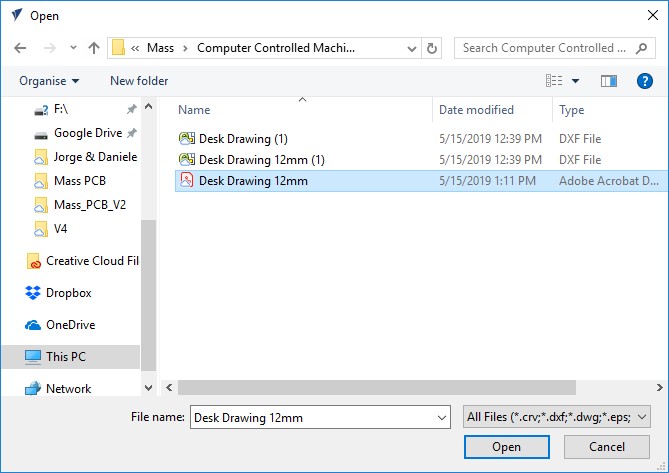
Now, the first step is the define the stock, or the material im going to use, and the origin of it. For this, I include the width, 1220 and height, 2440, and the thickness, 12mm, and then define the origin in the low left corner.
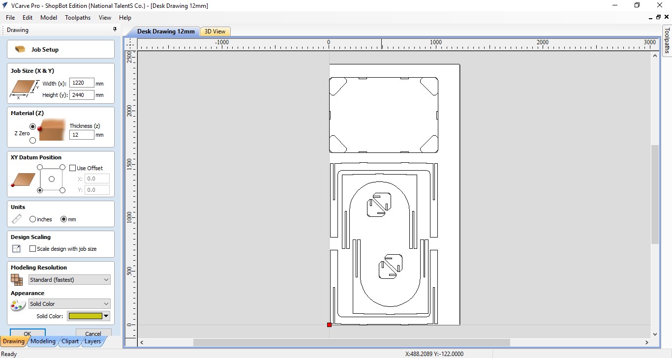
After a little rearrangement of the parts, I was able to fit them in only one sheet of wood as shown below.
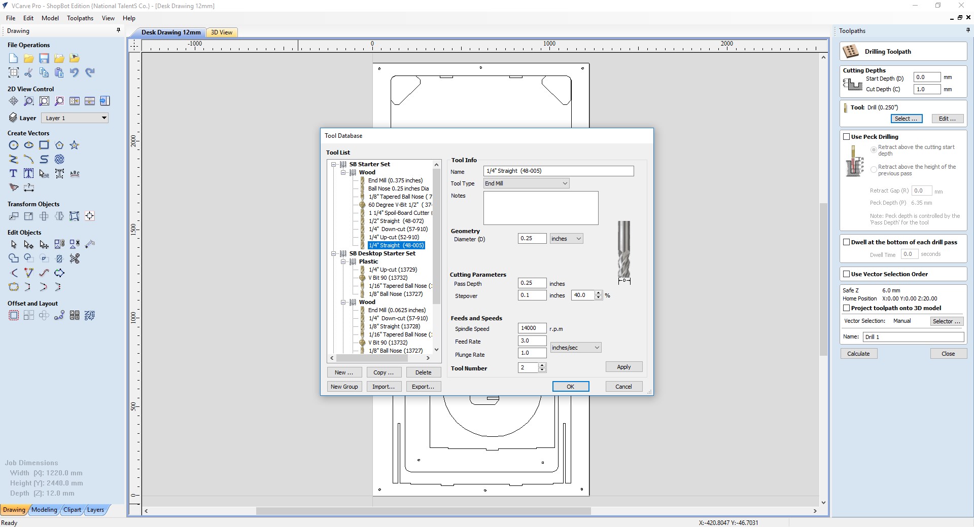
Now, I need to select the bit i will be using for cutting, which is a 1/4 “ flat
Now, I will begin by defining my pockets, or cut that are not going to be througg the material, but only 6mm depth, and which i want to complete remove all the material inside. For this, I use the pocket tool, and decide to remove the 6mm, in two passes, of 3mm each, to prevent breaking the bit.
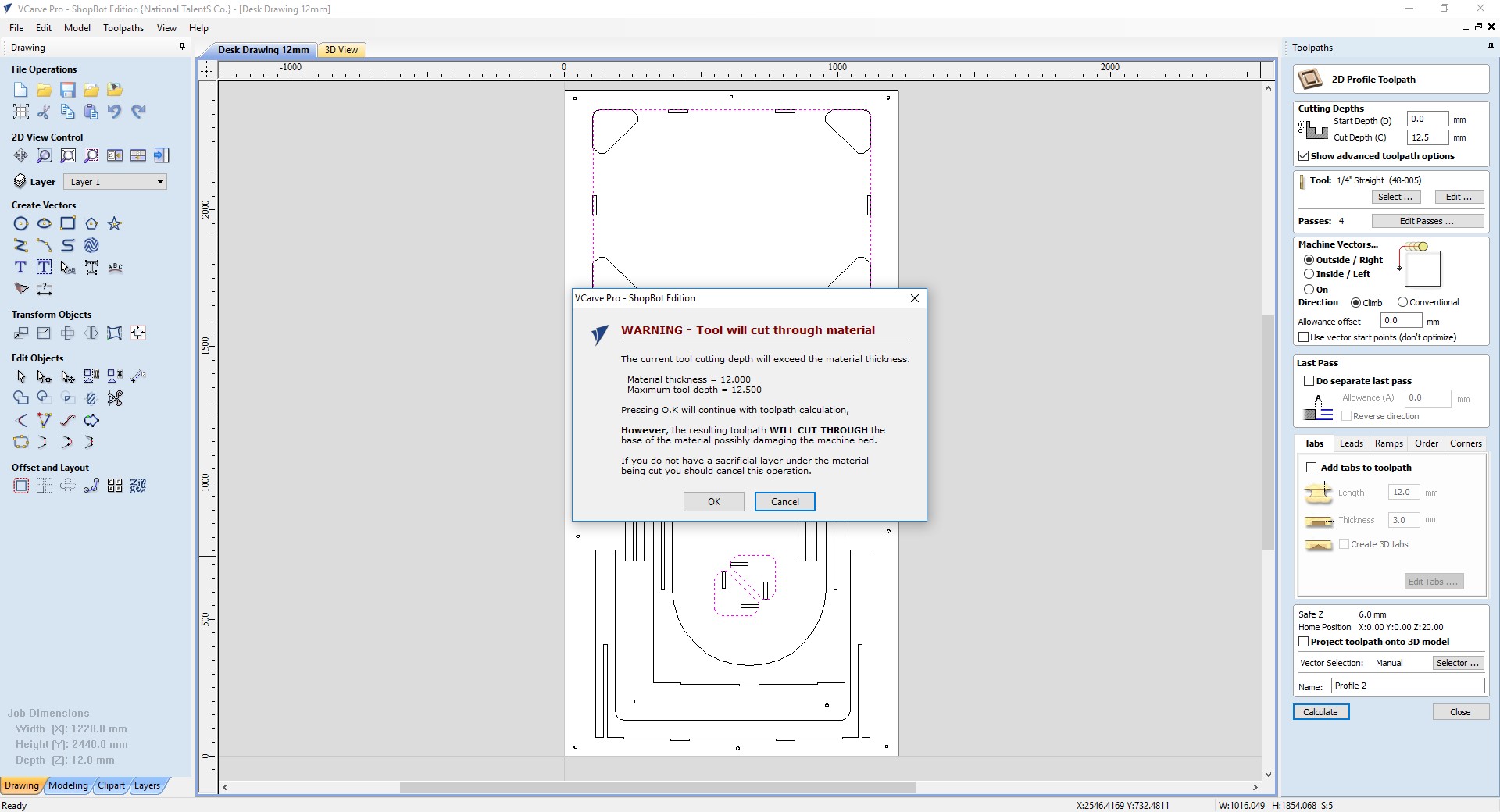
Then, I will define my cuts. For this, I select all the geometry I want to cut (12.5), and specify the pass depths(3.125mm per pass, so 4 passes in total).
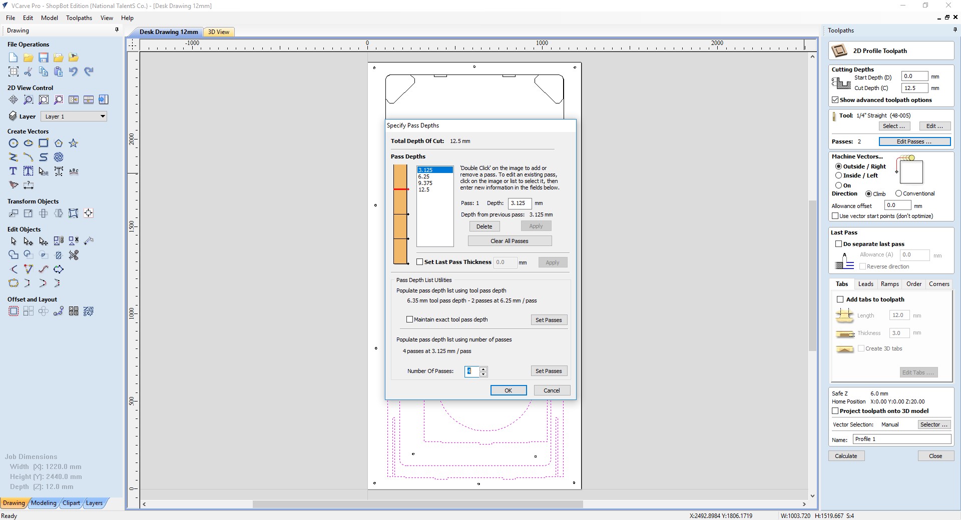
When accepting this values, I get a warning which says that the bit is going passed the material, as it was defined as 12mm and the cutting Im configuring is 12.5, but this ok because i will place my material over a another material for sacrifice, to prevent damaging the bed of the machine, and assuring my material is cut.
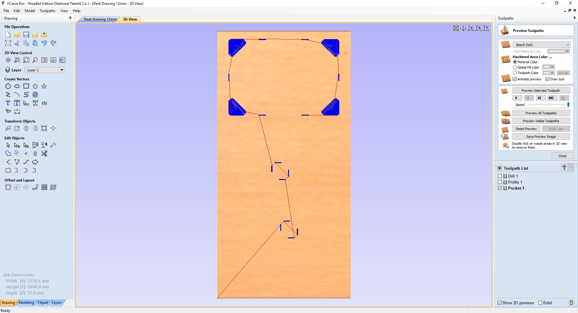
Now, I can preview the process to see if everything is ok.
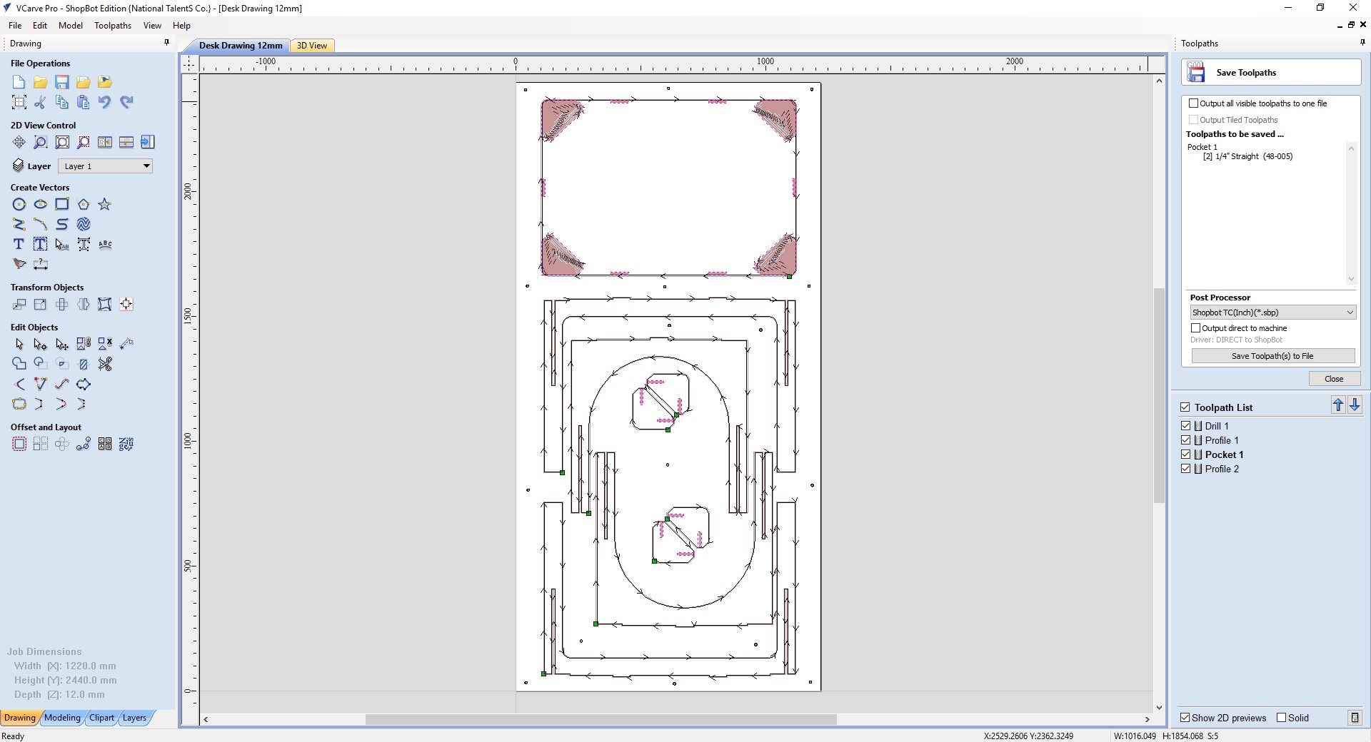
and once im ready, I can export the gcode for for machine.
Screenshot of the shopbot software is missing to finish this.
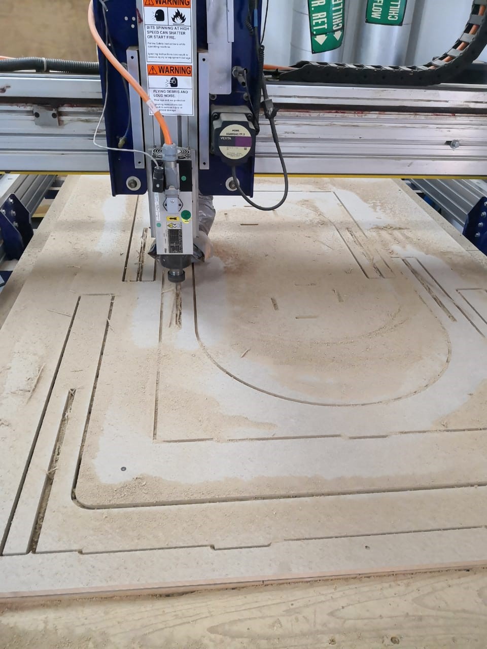
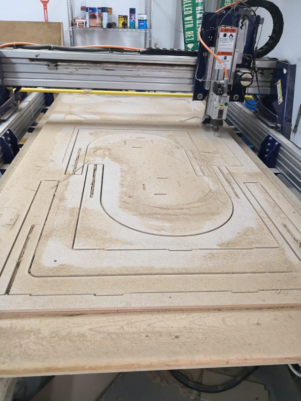
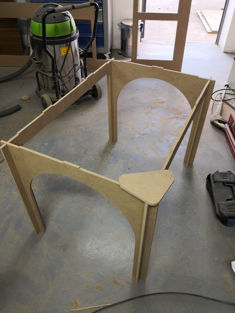
Now I begin the cutting process.
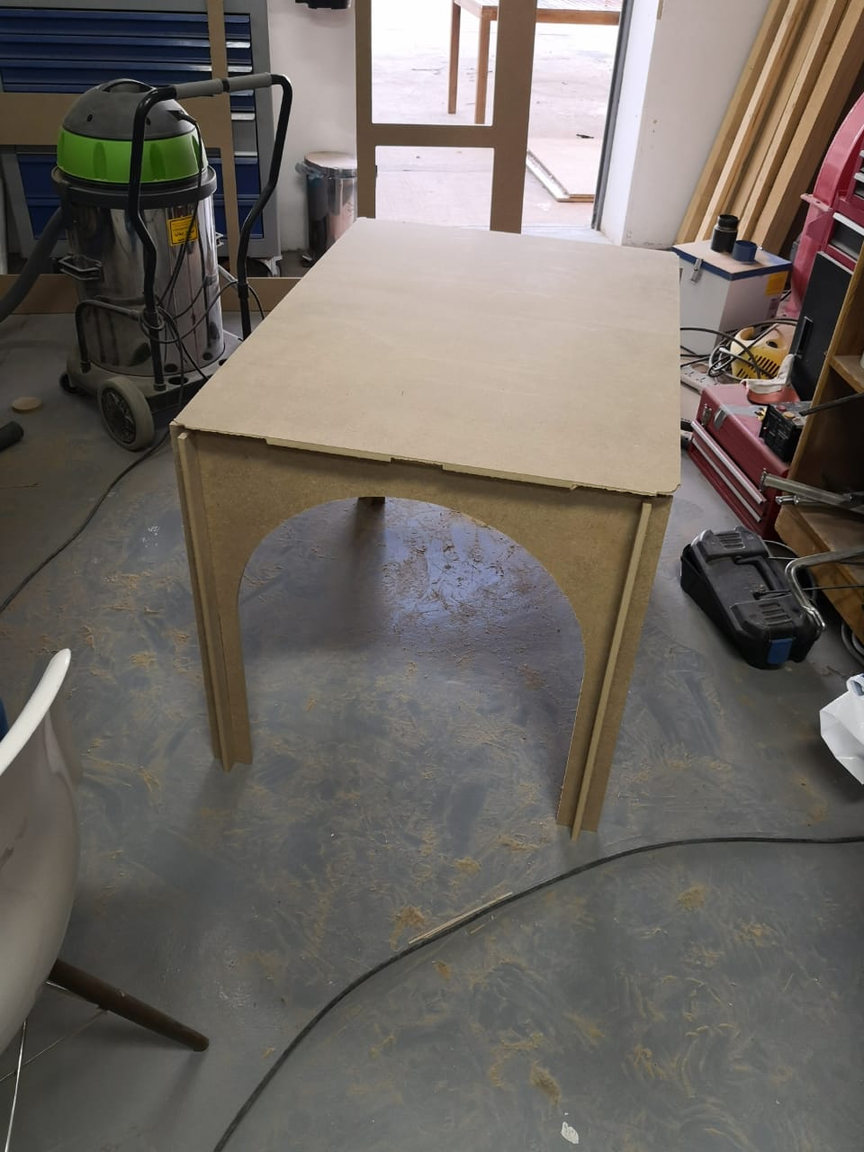
The parts fit perfectly and assembles with no problem.
The final product
Download File: Top.SLDPRT
Download File: sides.SLDPRT
Download File: joint.SLDPRT
Download File: Front.SLDPRT
Download File: Desk Drawing.DXF
Download File: Desk Drawing 12mm.dxf
Download File: DESK ASSEMBLY.SLDASM
Download File: Computer Controlled Machining CAM