Computer-Controlled Cutting
Computer Controlled Cutting
From last week, I have 2 Cad models I can use to cut and prototype my project. First, I will use the part model, and try to use the software slicer to prototype it. Slicer is a plugin from Autodesk that helps you slice any 3d model into laser cuttable parts. To be able to import my part from Inventor, I just need to save it as an Stl, and the open Slicer. Make sure to verify the size of your project. In this case, as this is a desk and I don’t want to laser cut it full size, I made it smaller so that I can make a small prototype.
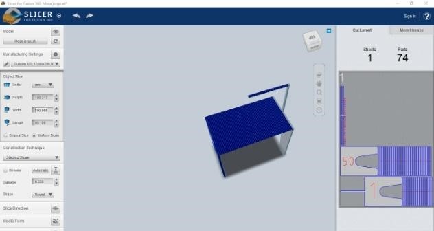
Some of the options you have are stacked or interlock slices, which could even be radial if the object was round or had a revolving axis. In this case, I selected the stacked slices, having the axis perpendicular to the legs. After reviewing the settings, you have too many parts to cut, and making this will be very difficult because you have to paste together more than 74 parts.
So in order to get a better laser cut prototype, I will use my second model, the assembly. As all parts are created independently, I will create a drawing off all my parts in TOP view.
.
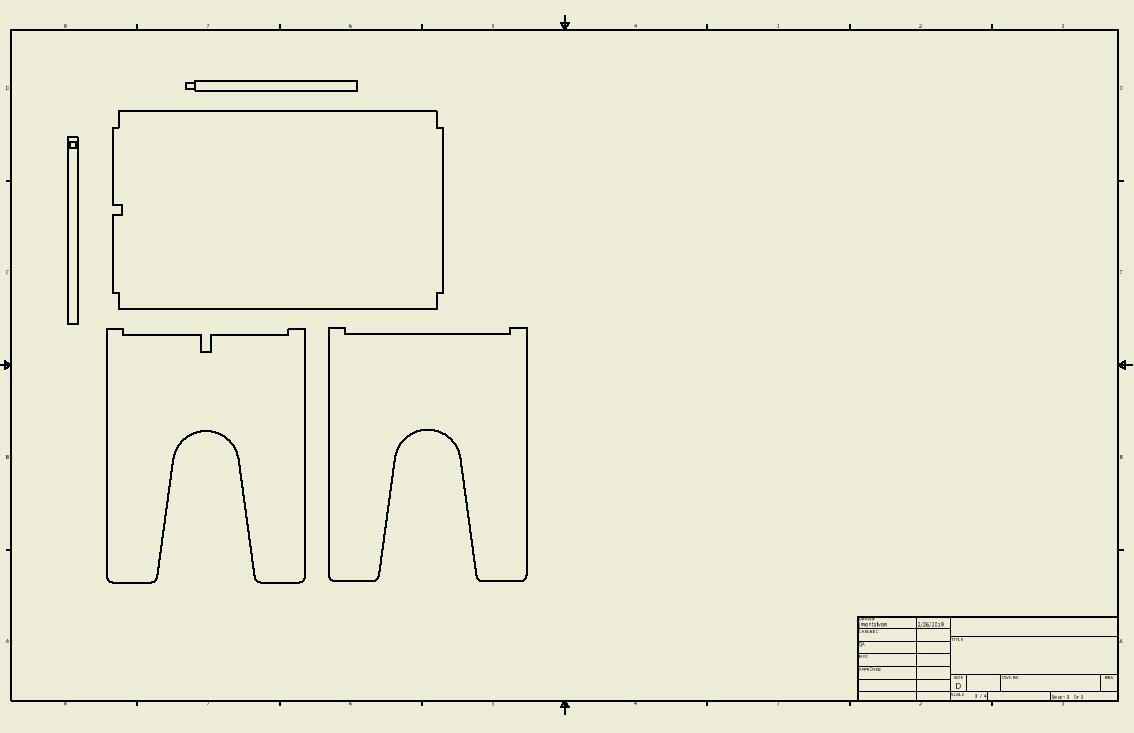
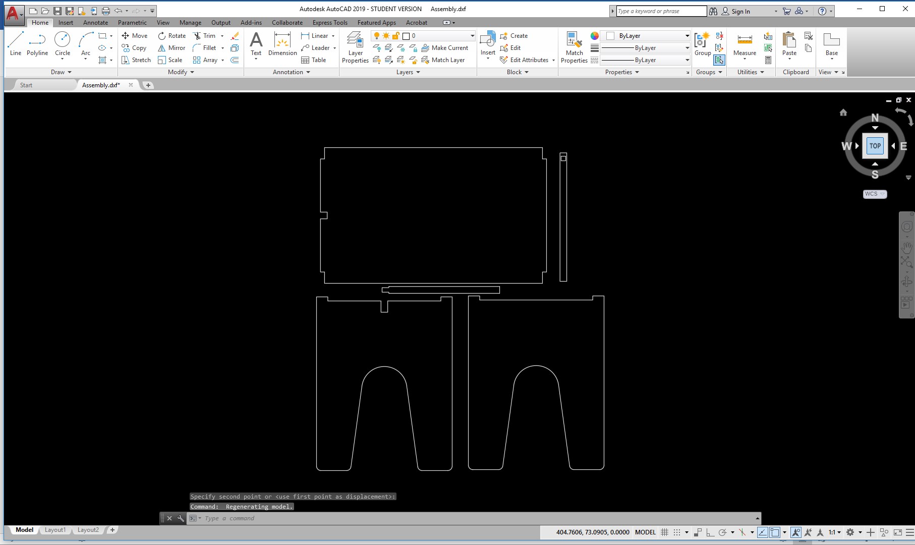
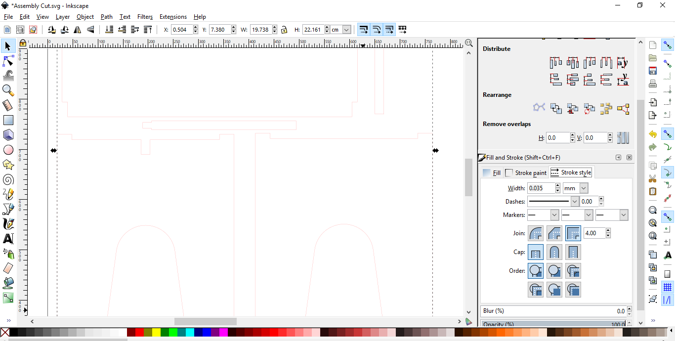
Now,I will save this as a DXF file, and delete the frame in order to only cut my parts in the laser cutter. Check the sizes on the DXF and scale them to the material you are going to laser cut it with to make sure they will fit. In this case, I will cut in a 3mm material, so I just verify that the size is correct.
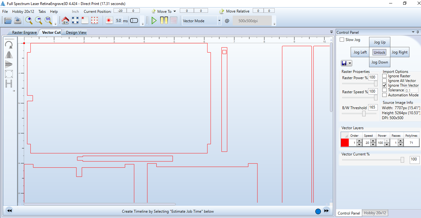
Now Im using the laser cutter machine (Full Spectrum Machine ) to fabricate the prototype .. I used the white acrylic to make the 2D parts then I will use the glue to assembling the prototype.
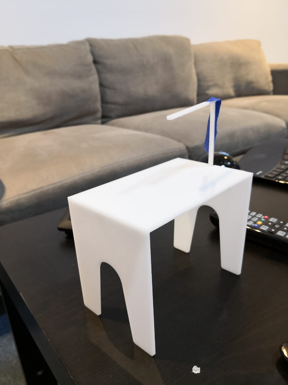
The final prototype was as the followings:
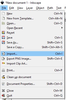
Additionally. For using the vinyl cutter, Im going to show you how to get the vectors out of a PDF file and cut it in the vinyl. For this, we are using inkscape. Open inkscape, and then go to import.
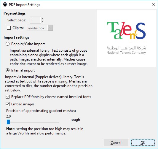
Now, browse for the PDF file you want to cut. In this case Im cutting the logo of my company.
The PDF will import as a group, so just go to Object Menu, and the select ungroup until the each individual part is showed in a selected square, as shown below. 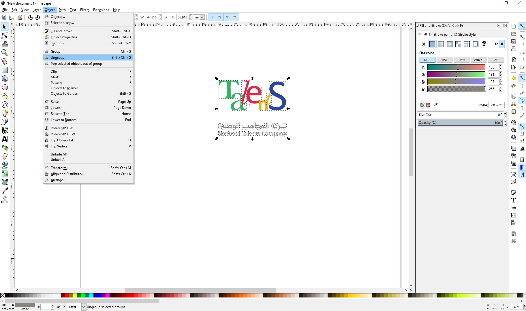
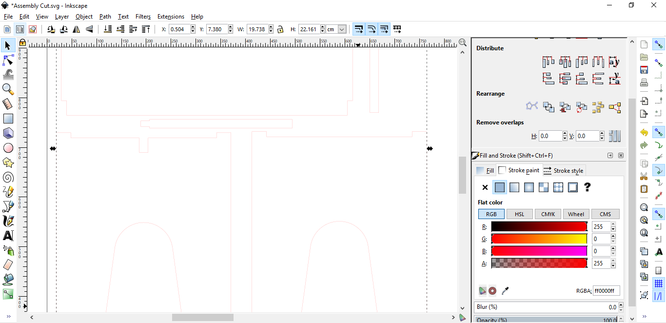
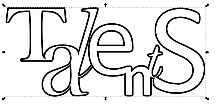
Now, we have individual vectors of the image, so to see how it would be cut in the vinyl cutter, select no fill and stroke color in the right corner. This would be what the vinyl cutter would see, so I will focus only on the big logo.

To make sure its possible to cut not as individual letters but in a single cut, I will select the “T” and the “a” by pressing shift and make sure that both letters are selected, and then press “ctrl” and “+” keys to make an union of this two element. As shown below, notice that the outer stroke is conserved, and the inner intersections disappear.

Repeat the same procedure with all the letters until you obtain the following result.
This is a simple stroke that can be vinyl cut without problems. So just export the file as DXF and you are ready to send to the Vinyl Cutter.
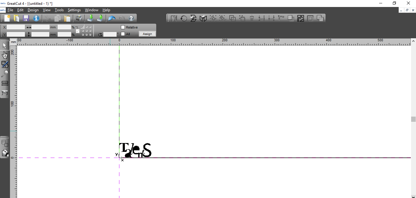
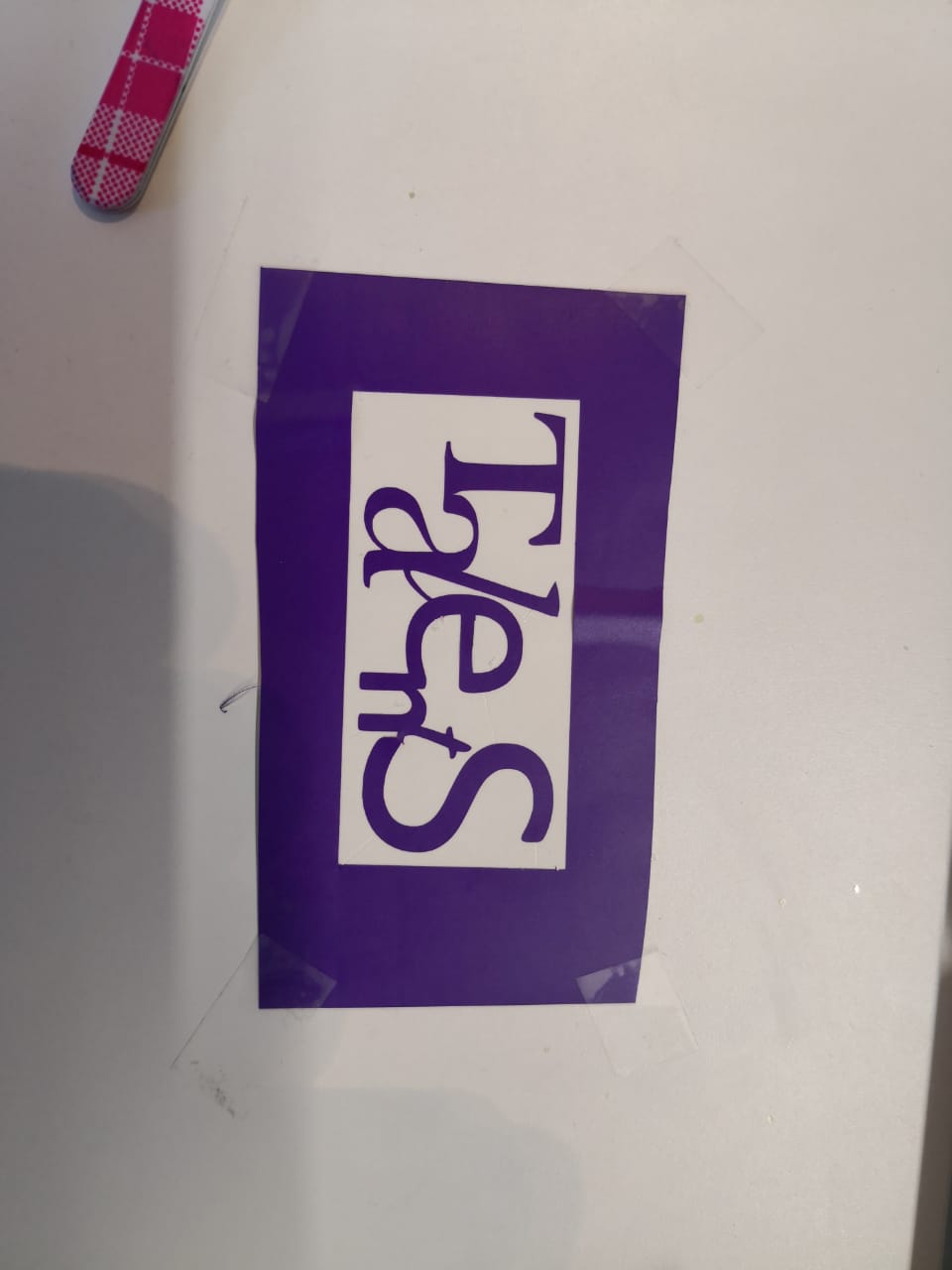
Then I used the blue vinyl role to make the logo
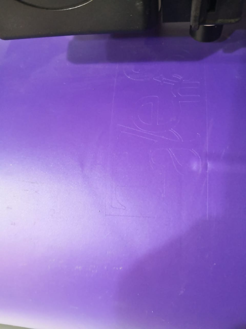
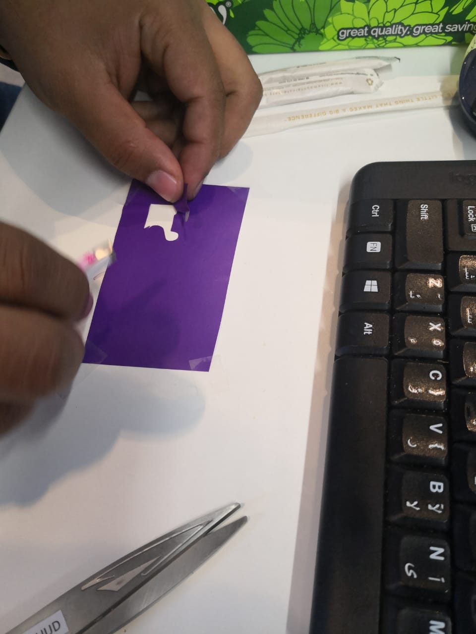
Then .. I take the logo from the vinyl sheet to the small peices of vinyl and stick the vinyl from the corner and using the twezers to take off the frame
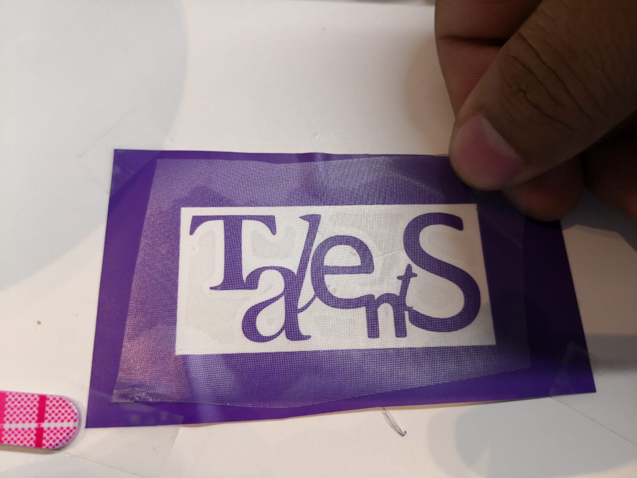
Now The logo is ready .. I used the transferable tapr to take the logo from the vinyl sheet
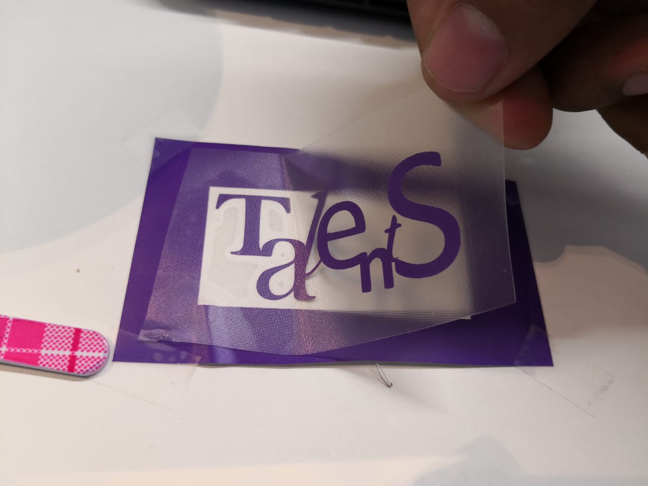
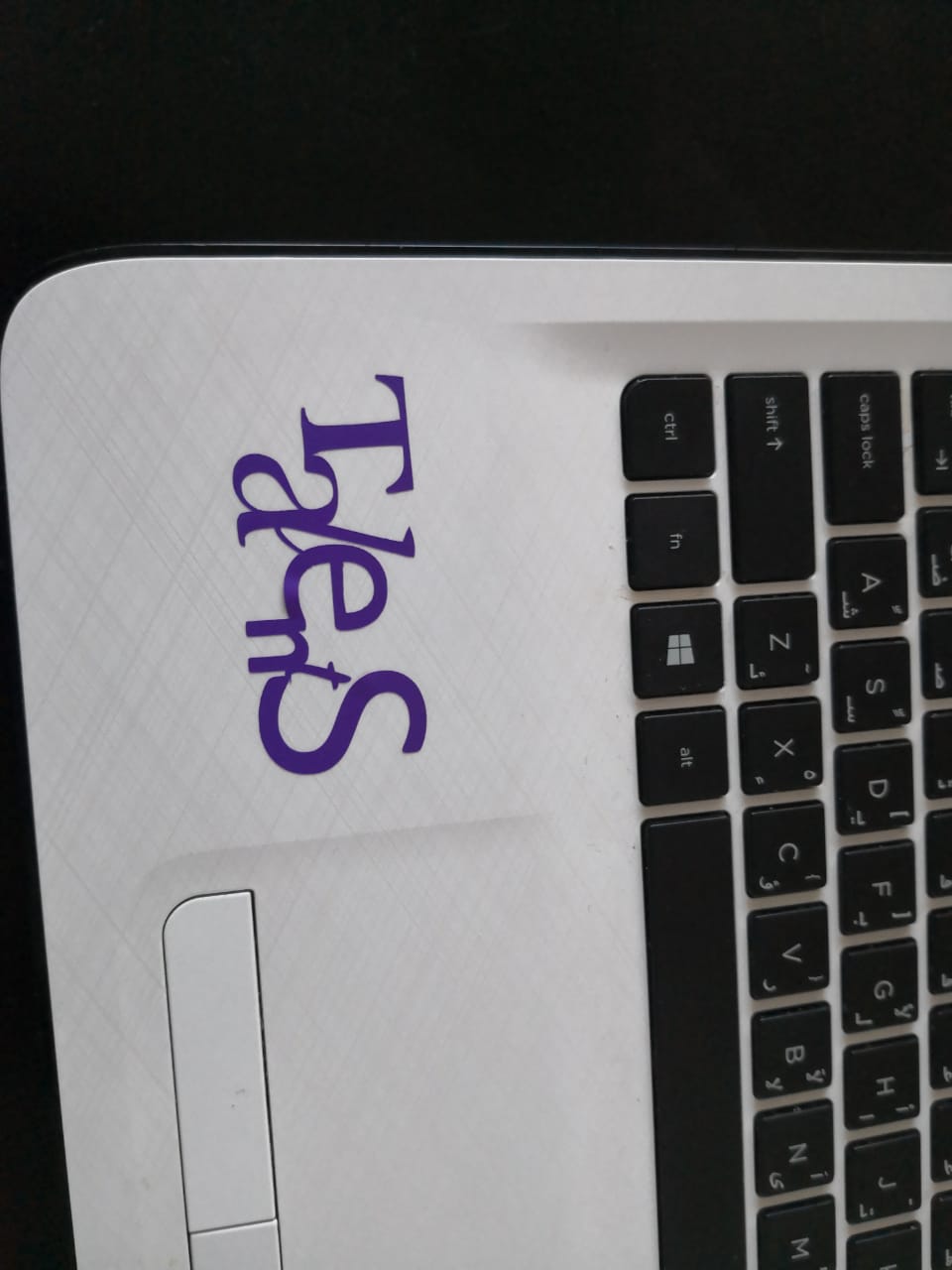
Then I put it on my Laptop as the final stage of the prototype
Using the same file, we can create a patter to characterize the power and speed of the laser cutter. For this, I created 10 copies of the file in autocad as shown below.
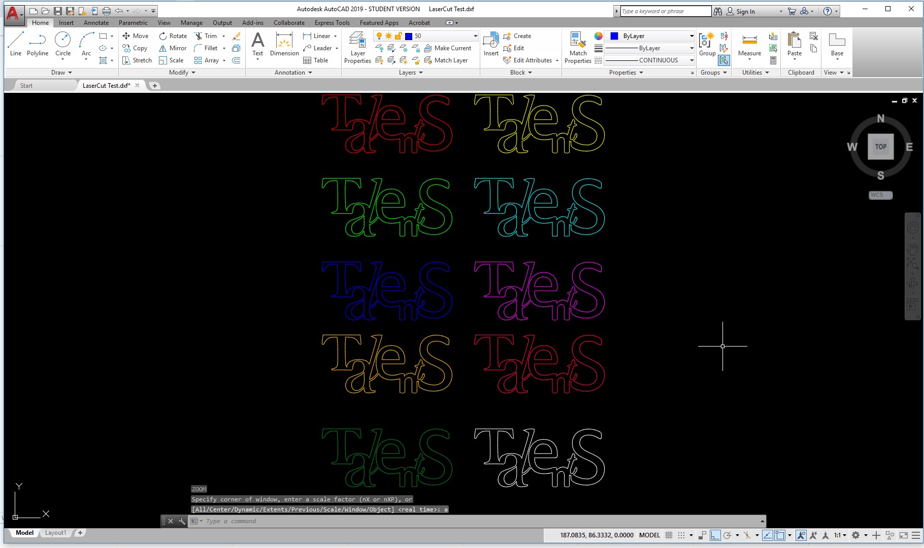
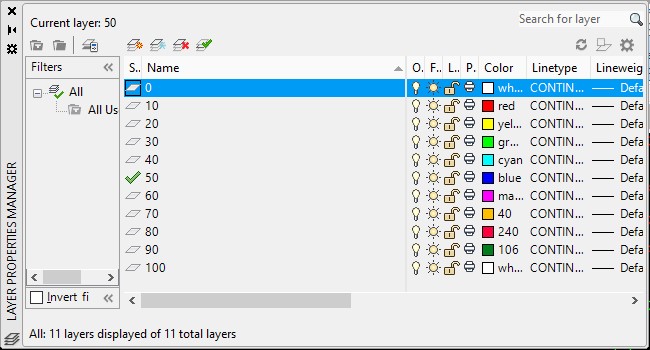
Each copy, was set to a different layer and color, so that its easier in the laser cutter to select a different setting for each in intervals of 10%, as shown below.
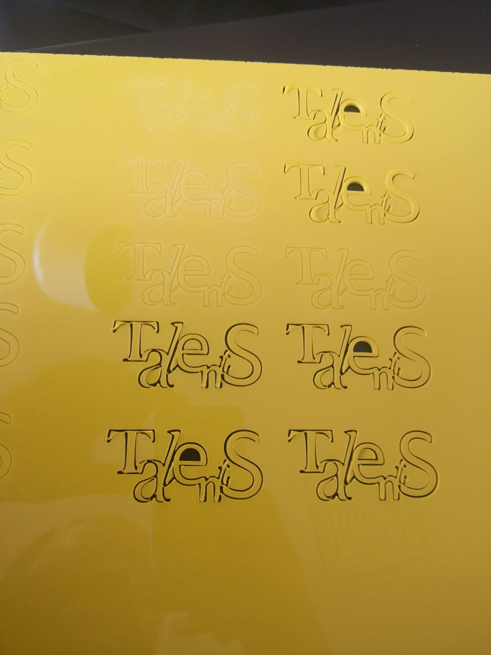
Now, I will use the laser cutter to cut each one at 10% intervals for power, and then, with a medium power, will do the same but this time changing the speed.
the final prototype looks as the followings:
For a press fit design, I will explain how I did the LDR box for my final project
Inkscape is a free graphic vector editor, free and open source, you can create and edit vector graphics such as illustrations, diagrams, lines, graphics, logos, and complex illustrations. The main format used by the program is Scalable Vector Graphics (SVG) version 1.1. Inkscape aims to provide users with an open source tool for drawing graphics in Scalable Vector Format (SVG) that fully complies with the XML, SVG standards and CSS2. It is also developed primarily for the GNU / Linux operating system, but it is a cross-platform tool and works on Windows, Mac OS X, and other Unix-derived systems.
Inkscape software download
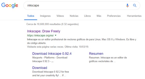
Go to your browser and in the network through a search engine (Google, Bing, Yahoo!) write in the search bar Inkscape.
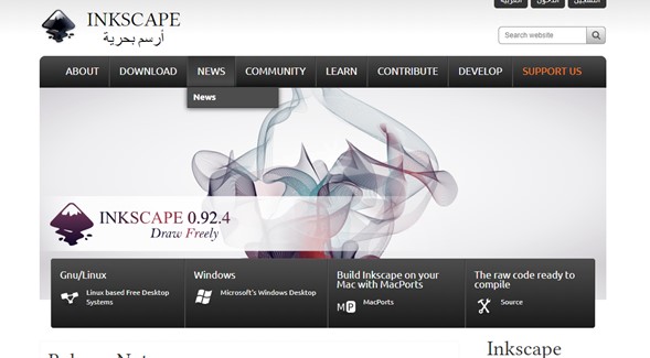
Followed by this move to the downloads link, where you will find three options for three different types of operating system, depending on what you have on our computer you will choose the requested option, in this case it will be Windows.
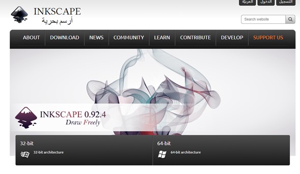
Already within the option of your operating system look for the most updated version of the software, in this case it will be (0.92.4); you must take into account what version of operating system we have (x32bits or x64bits) when downloading your file.
When clicking on your download option mentioned above, a menu or window is automatically displayed asking about the download location of our installer file (inkscape-0.91-x64); select your location and click on the save button
.
When your file is downloaded, proceed to look for it and execute it by double clicking on it and following the steps of the installer.
Once the program is installed, look for the icon on your desktop and double-click on it.
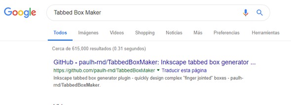
Once you have the software you need to find the necessary extension to be able to develop your boxes with their respective pieces of assembly; the extension is Box Maker, for it search and installation you have us to search in the Google search bar under the title "TabbedBoxMaker" and enter the first option of results (GitHub).
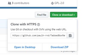
Already inside the GitHub page click on the green download button called "Clone or donwload", this displays another window, where we click on the "Download ZIP" link and will automatically start downloading the extension files.
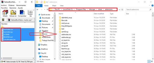
Having your compressed file, open it and extract all the files inside, to deposit them in the installation folder of the Inkscape program located by default in the following path: ThisPc / LocalDisk (C:) / ProgramFiles / Inkscape / Share /Extensions.
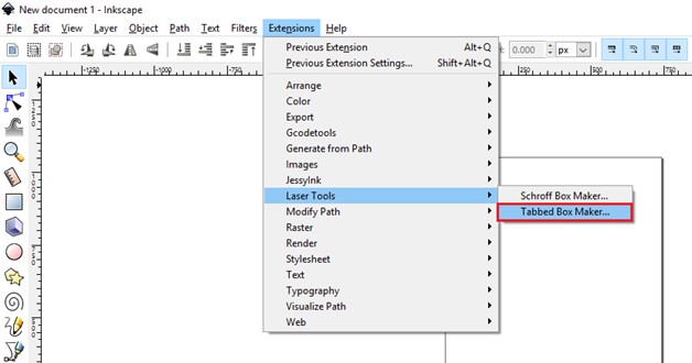
Done this step, open again the program Inkscape, go to the tab Extensions> Laser Tools and find the option Tabbed Box Maker.
Next is the explanation of each parameter and its values for its use.
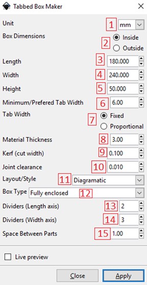
1. Unit: Select units in millimeters (mm), centimeters (cm) or inches (in).
2. Box Dimensions; it refers to the dimensions inside or outside the box.
3. Length: enter the value of the length of the box.
4. Width: enter the value of the width of the box.
5. Height: enter the value of the height of the box.
6. Minimum / Prefered Tab Width: corresponds to the value of the tab, this is calculated by taking the smallest value of the dimensions of the box multiplying it by 1/3.
7. Tab Width: size of the tab which can be fixed or proportional to the adjustment made to the dimensions of the box.
8. Material Thickness: enter the value of the thickness of the material,
9. Kerf (cut width): refers to the cut of material that is burn away by the laser. The software compensates by making the box slightly bigger, so the final measurements you get are correct. In this case a value of 0.100 mm compensation of the cutting tool (laser) is appropiate. If you make this value bigger or smaller, the press fit of the box wont fit, and it would be very difficult to assembly your box.
10. Joint clearance: refers to the adjustment that the tabs will have when fitting a tab with the housing. This value can be predetermined or adjusted to the need. Preferably work with a setting of 0.010.
11. Layout / Style: refers to the views or pieces required in the design.
12. Box Type: corresponds to the box type either open or closed completely.
13. Dividers (Length axis): separators in the longitudinal axis of the box.
14. Dividers (width axis): spacers across the width of the box.
15. Space between parts: space between pieces, usually a value of 1 mm is taken so that the waste of material is minimal.
16. Apply: entered the dimensions click Apply to see the design of the box.
For our case when you enter the values you should have something as the following pictures
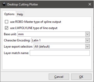
Once your box is complete you can save the file as a .dxf to continue editing on a CAD software as AutoCAD.
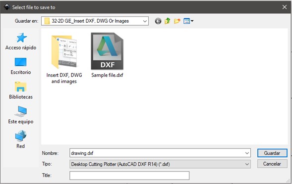
When saving a dxf file from Inkscake be careful on selecting the plotter parameters as shown in the next picture. Always select the units that matches the ones on your design.
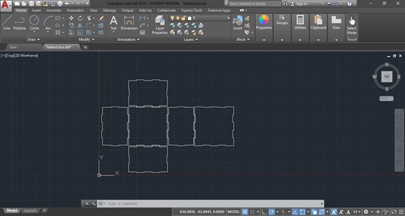
Open your dxf fiel on AutoCAD.

On the center of frontal face draw a 72 x 26 mm rectangle. And on the lateral faces, draw an arch of R 10 mm on the upper center and trim the line, as shown on the next figure.
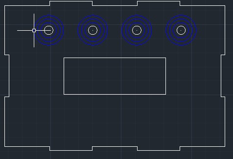
Finally draw a circle with R 3 mm and replicate it over the frontal face. Then using the offset tool create 3 more circles with a 2.5 mm difference. You should get something as the following figure.
The great part about autocad is that its totally parametric. When I add parameters, like for example for the slot for the lcd, I can use dimentions with names, as shown below
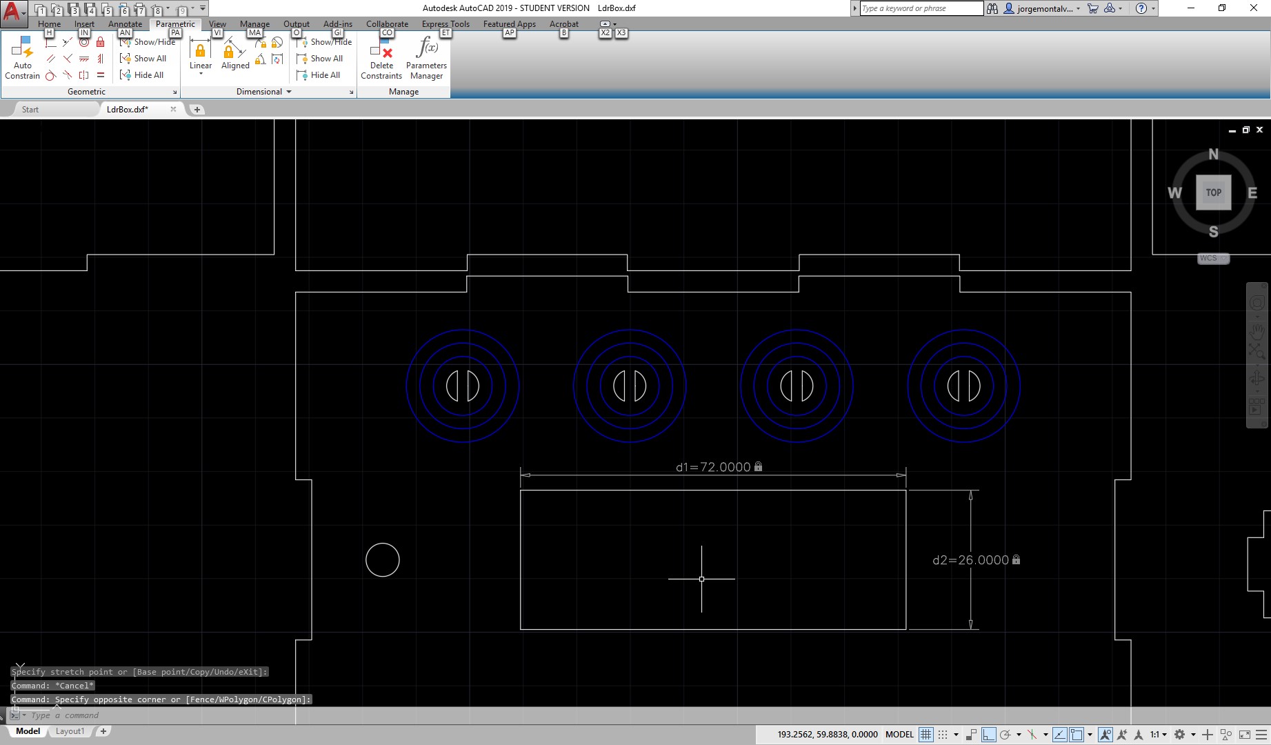
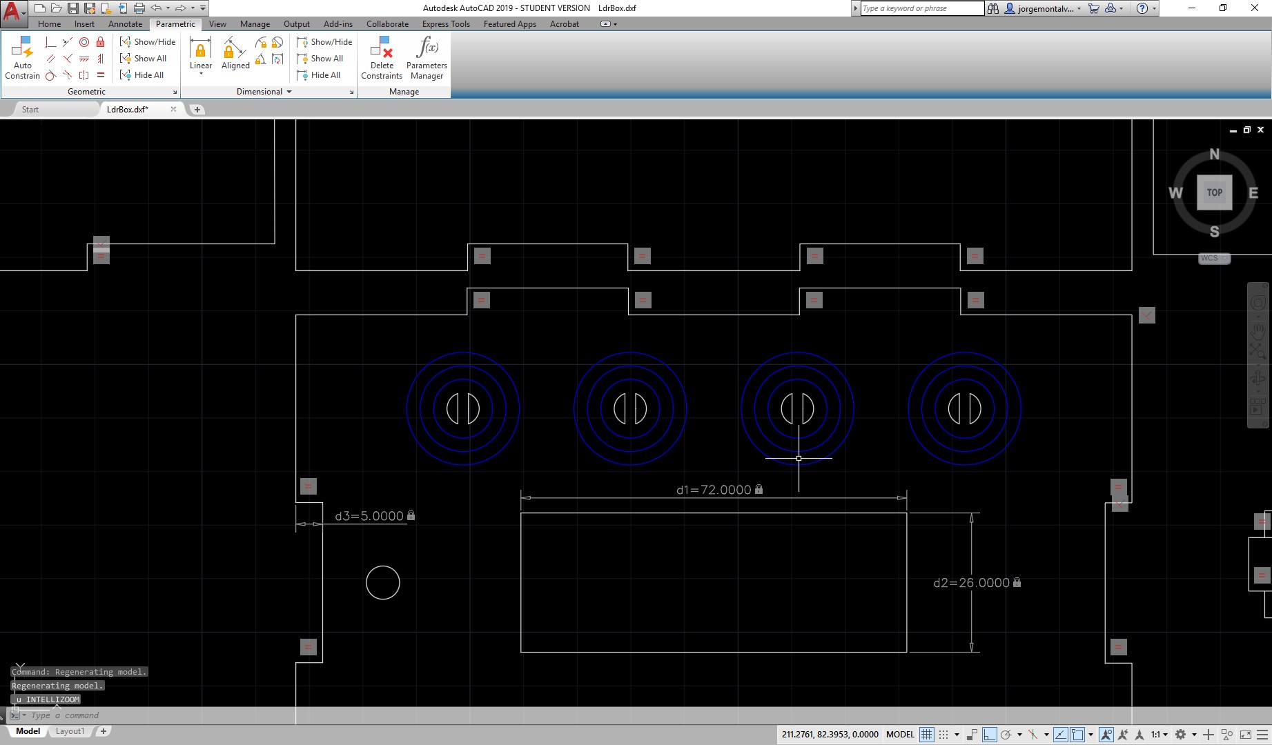
This dimentions name can then be used to control other parameters, or make matematical operations between themselves, and if used in conjunction with geometric constrains, you can control your design at your will. For example, I could make all the tabs widths, which are now 3mm, have an equal constrains so that they are all the same lenghts, and then add a dimention to control one of the widths, and change it for example to 5mm, and all of the tabs will change automatically, as shown below:
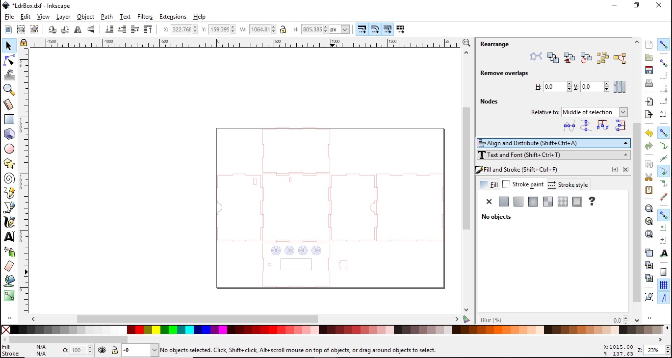
Once my design is ready, I save it as a dxf and im ready to send it to print. I open it in inkscape, and see that the layers I had prepared in autocad are still visible in this software. This will be important to determine what to cut and what to engrave.
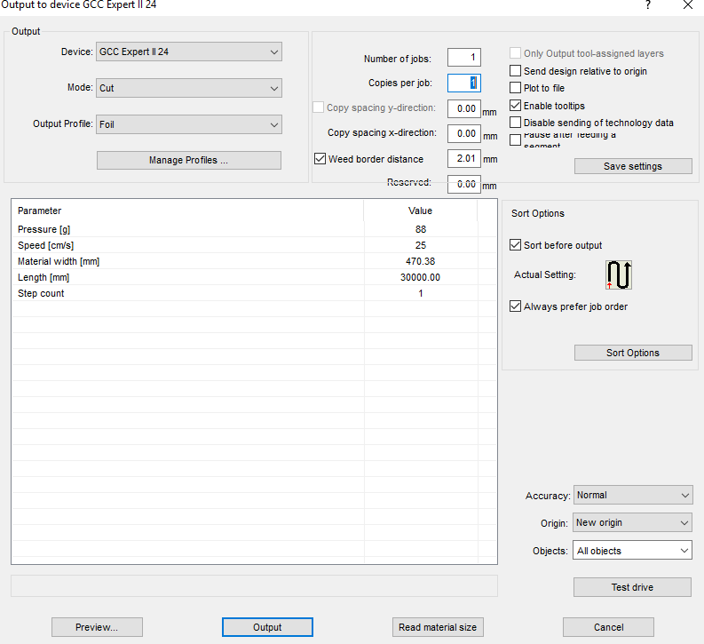
THen I go to file and select print, and select the full Spectrum Laser as a printer,
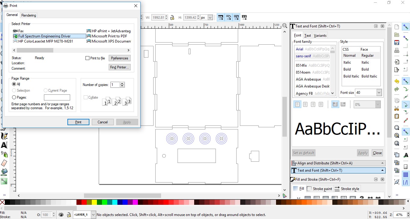
And when I send to print, in the full spectrum laser software, I will determine for each layer, a speed and a power setting the determine if I want to cut or engrave.
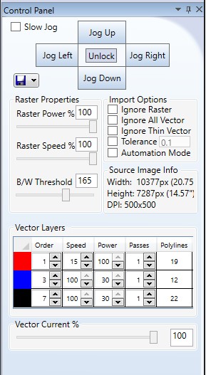
As seen in the above picture, I will use 15% speed and 100 percent power to make sure the outer perimeter of my box is cut, but for the circles, I will use a 100% speed and 30% power, to just engrave them, as they will be marks to later place the vinyl cut marks.
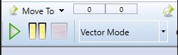
Once Im ready, I make sure the Vector Option is selected, and press play to begin cutting my 3mm MDF
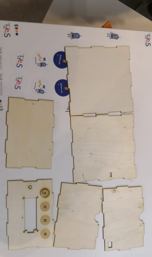
After removing from the machine, I realized I had some double lines under my first circle, and that is why it was engraved a little more than the rest, but apart from that, the results where just as expected, and the fit was perfect.
PARAMETRIC PRESSFIT KIT
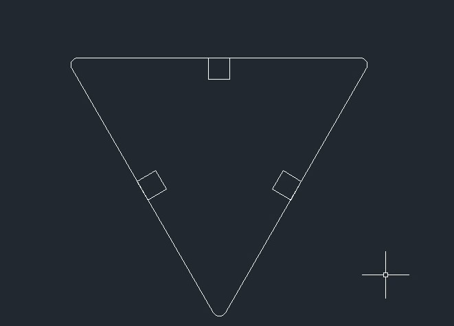
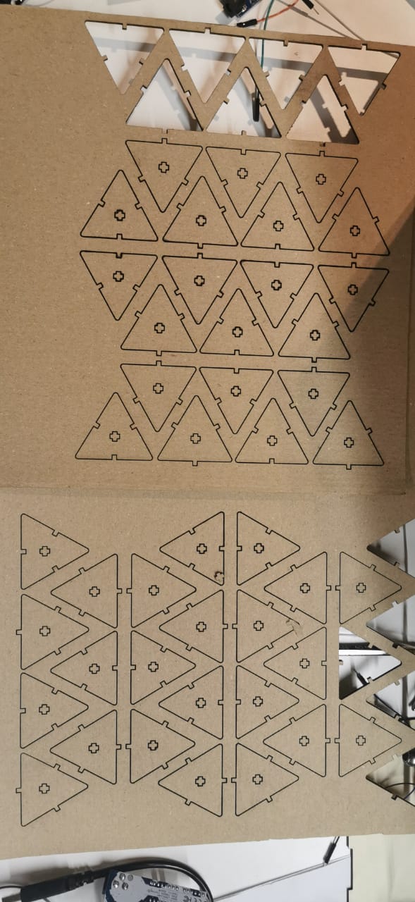
For this, I will begin with a triangle, by using the draw 🡪polygon 🡪3 sides tool 🡪25mm radius option.
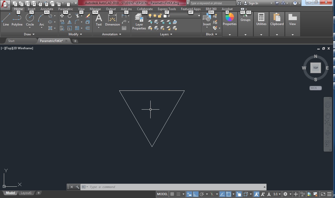
Then I ill add a fillet on the 3 corners of radius 2

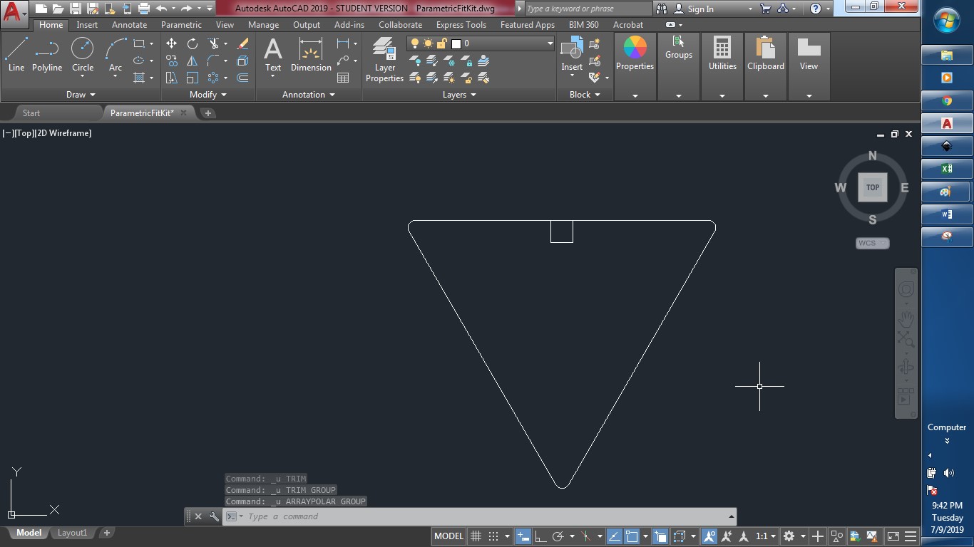
And then I will create a 3 x 3 mm rectangle under the midpoint of the horizontal line, as shown below:
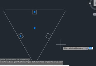
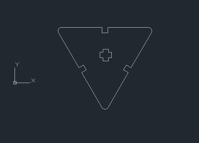
Then, I will create a circular array of this rectangle, with 3 repetition using the center of the triangle as pivot point.
Then, using the trim command, I will remove the borders of the rectangle to pass from the image on the left to the image on the right.
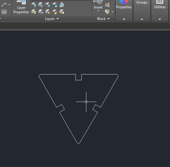
And finally will draw two rectangles in the middle and trim to get this shape:
To make it parametric, I will begin by adding equal constrains between the lines.
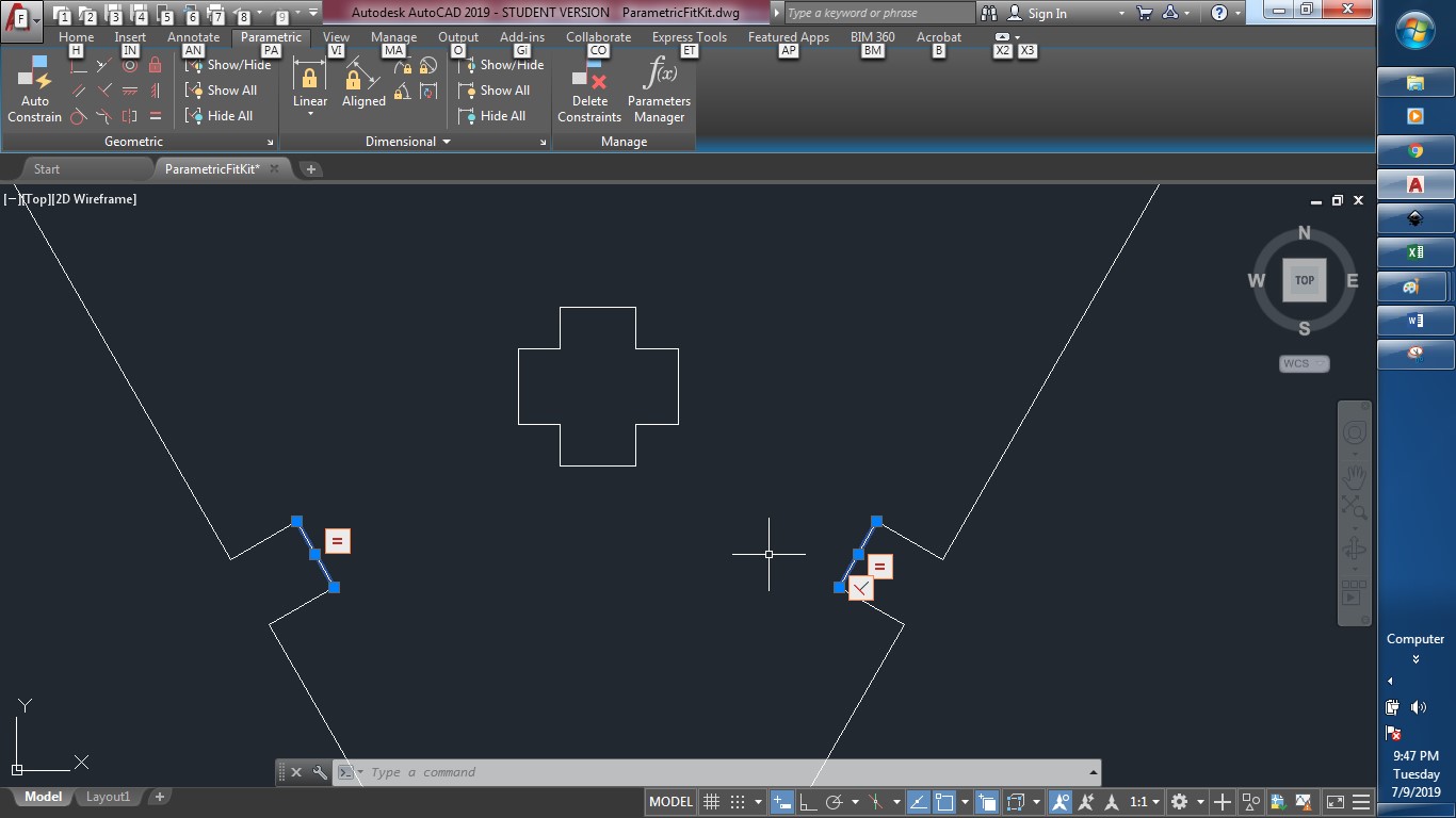
Then, after adding the constrains, I will add parametric dimensional constrains, and name them as shown in the following images.
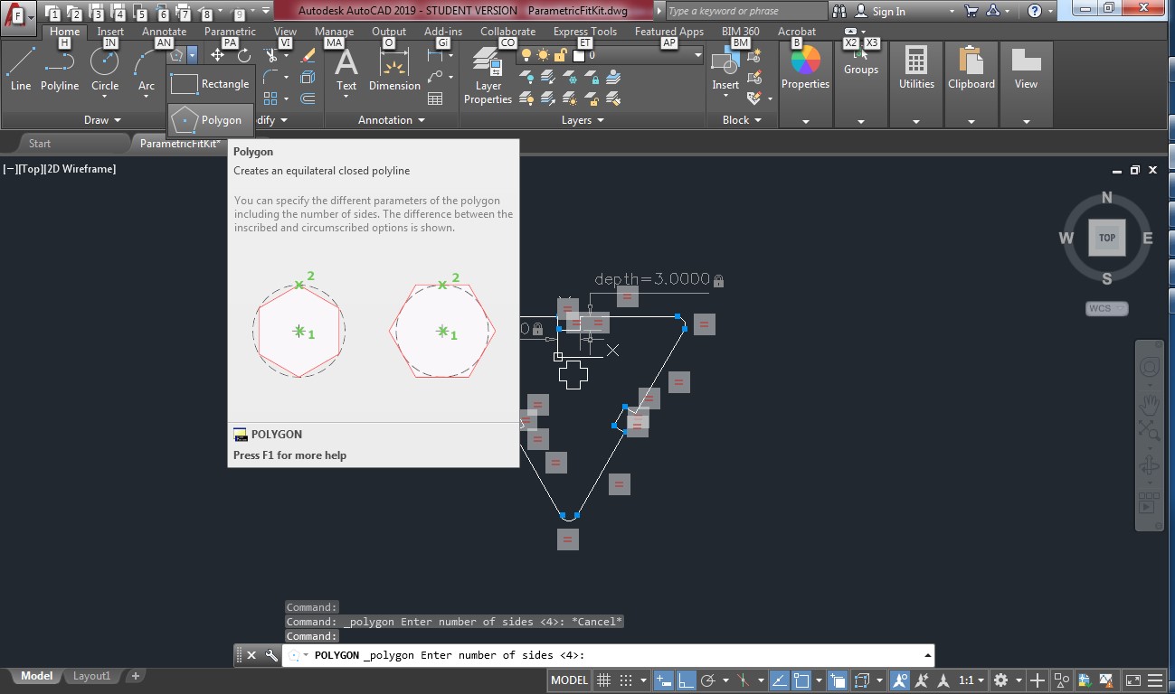
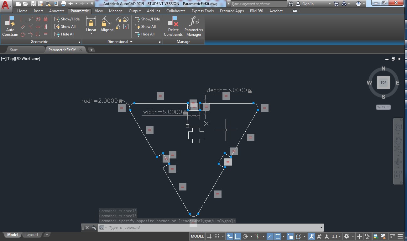
Then, In the paramer tab, you can call the parameter manager,
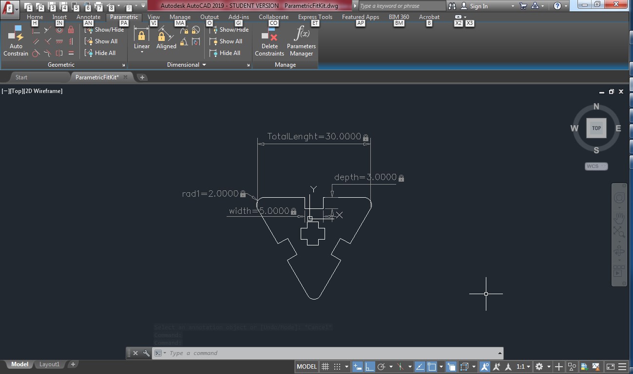
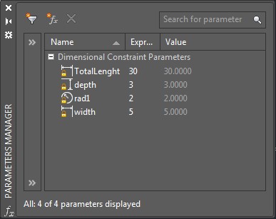
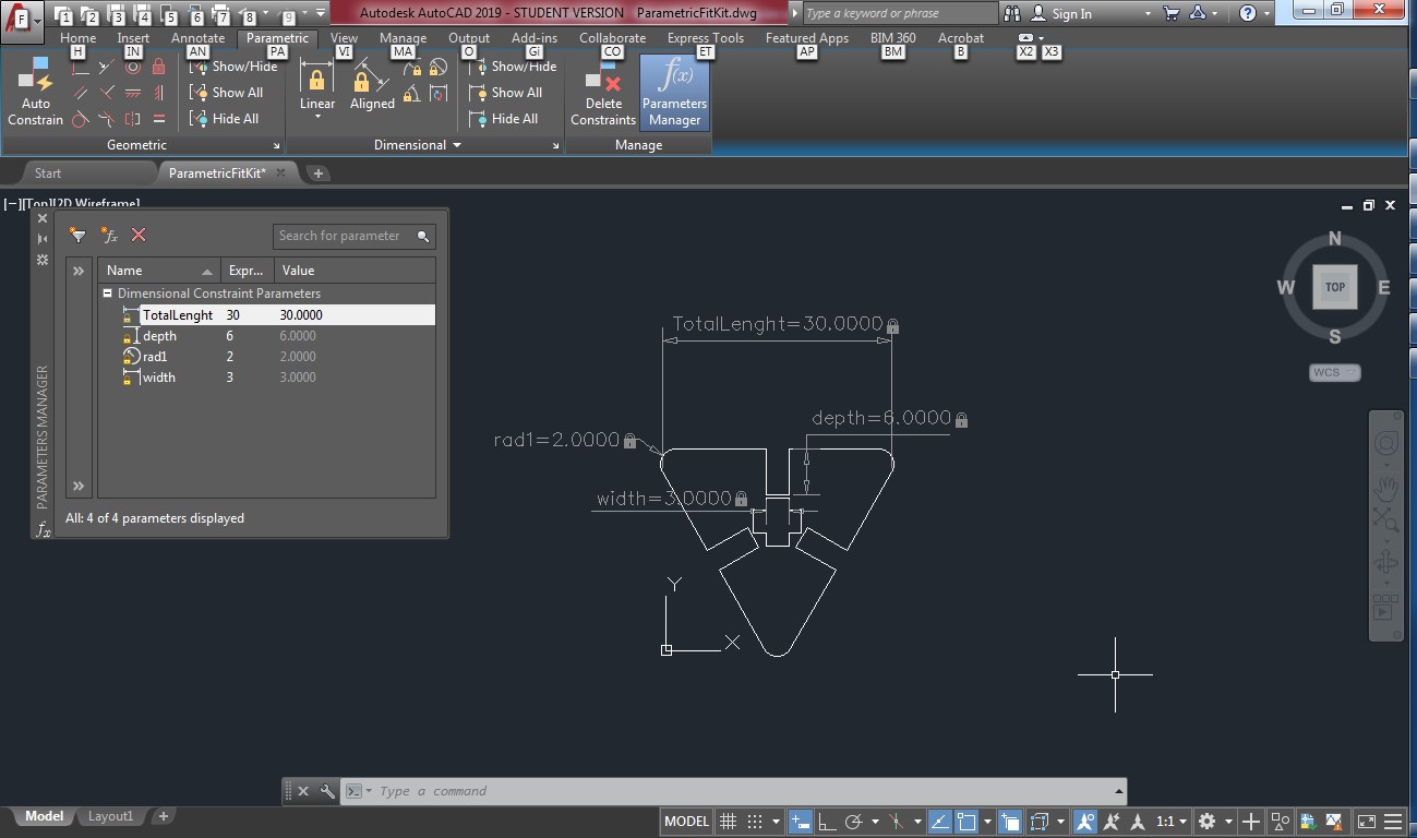
And when you change the numbers, the figure will change accordingly, as shown below:

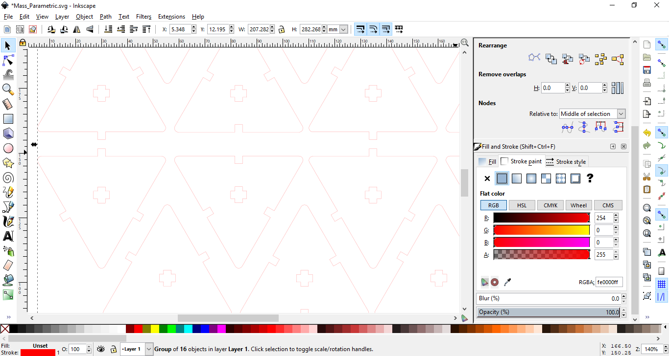
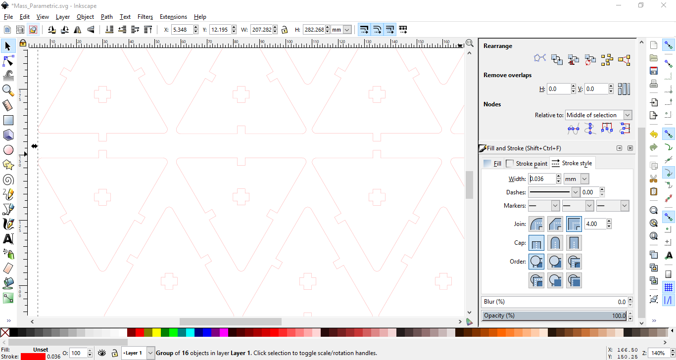
Now, We can laser cut them using the same process for fullspectrum machine. The program is called RetinaEngrave. I save the file as svg and opened it using the program. It's important to note that the cut part should be with no fill, only red strok with 0.035mm depth. The engrave part should be filled black. All what I have is cut parts, I edited the strok and changed the color to red
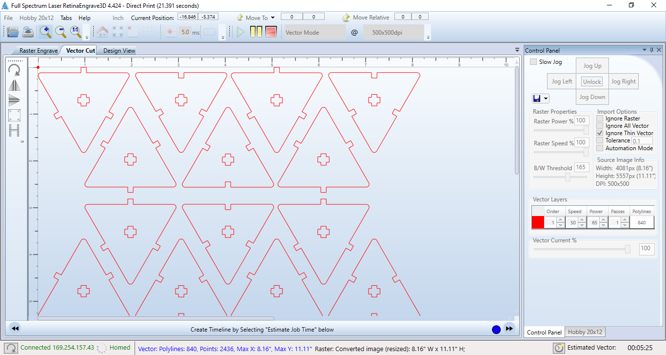
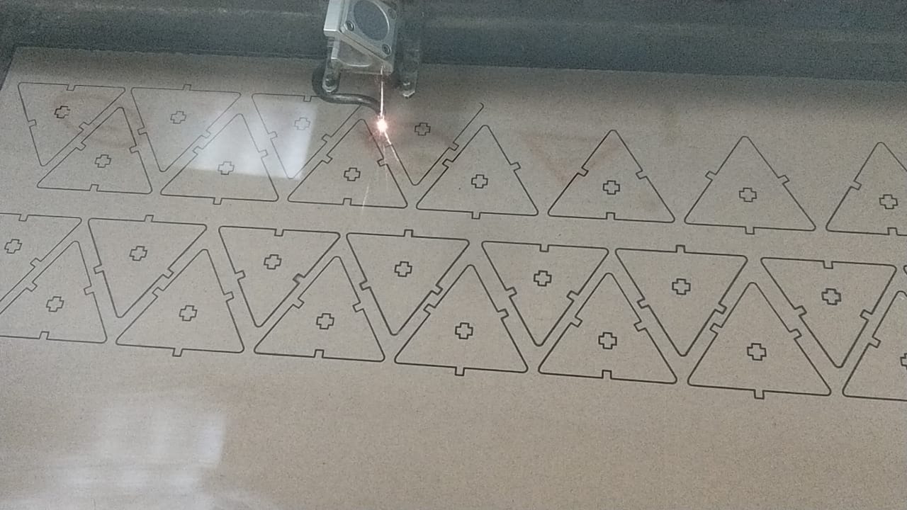
I clicked on the file, then print, then selected the full spectrum driver (it comes with the program installation) then clicked ok. The design opened in the program directly. I set the power 75 and speed 45 and selected vector only
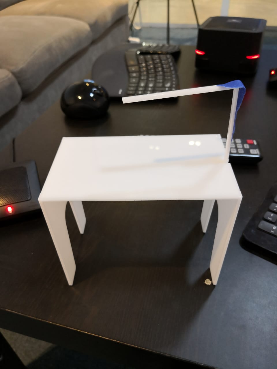
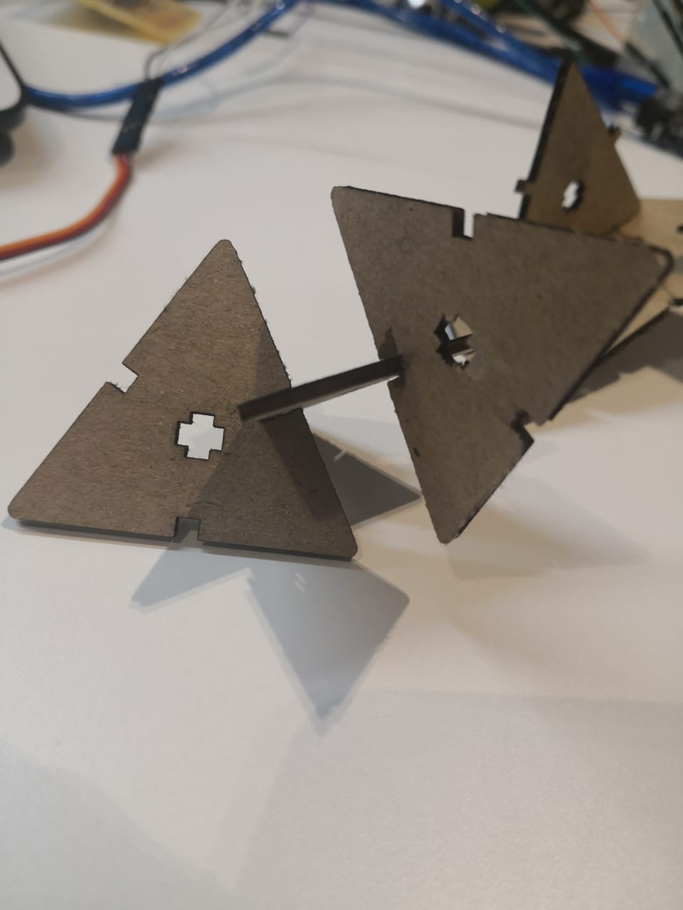
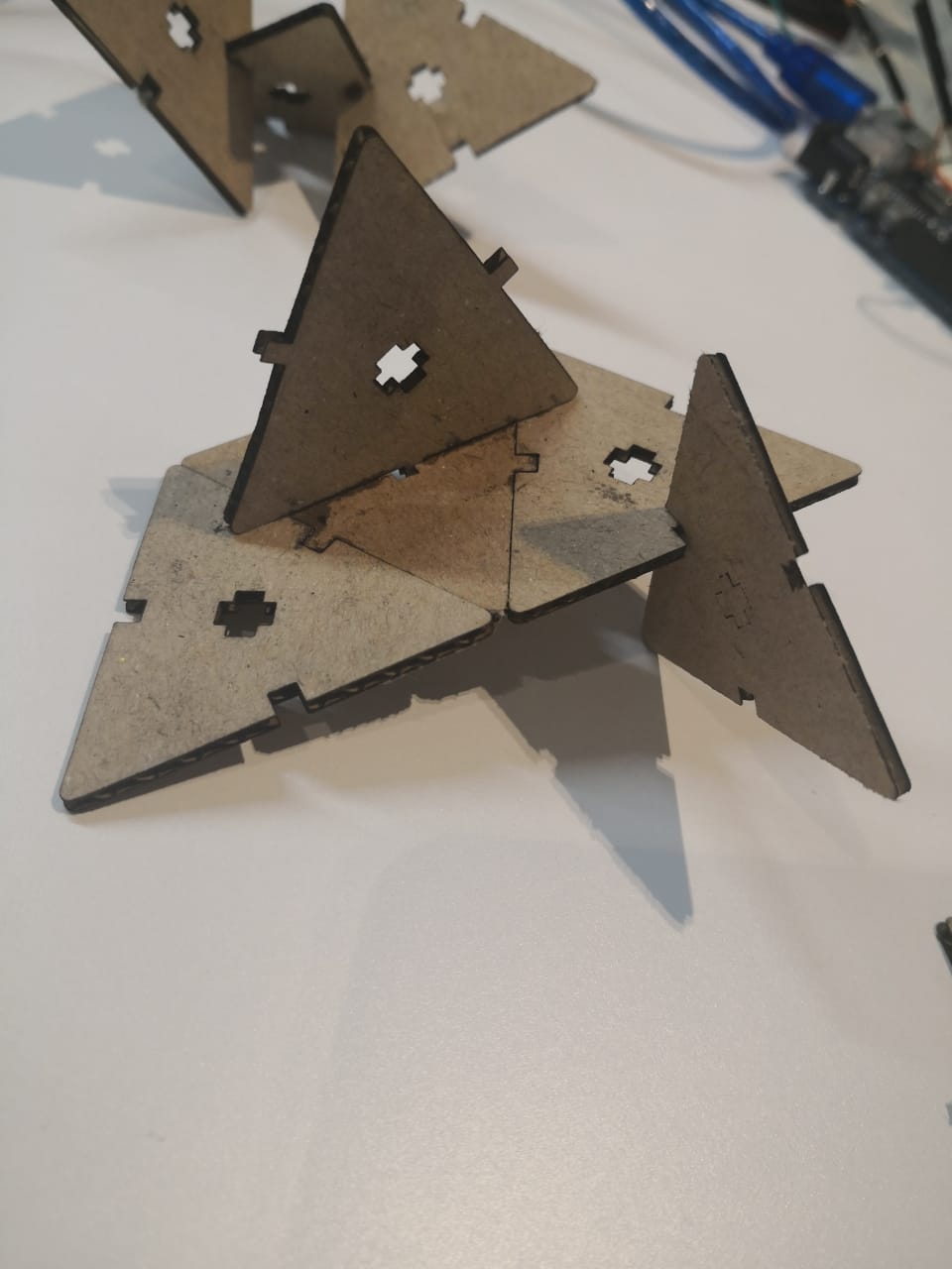
And after cut, we can assemble them in many different ways
Video for laser cutter
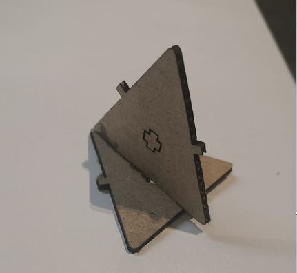
the final result
Then I assembled in differant ways
.jpeg)
Downloads
Download File: Parametric.svg
Download File: TalentS_Vecor_Logo
Download File: Laser_cutter_Test
Download File: Table_Assembly
Download File: Slicer.dxf
Download File: Assembly.dxf
Download File: Slicer.3dmk