computer Aided Design
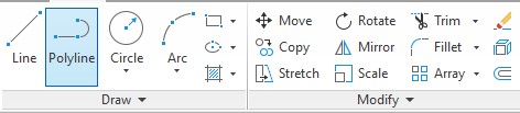
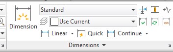
For 2d Design, I will use AutoCAD, which I believe is one of the best software for drawing as I have used it for a long time now. Once you begin, you can use all of these tools for drawing the shape you need, and as you draw, you can input your size, as its a parametric software.
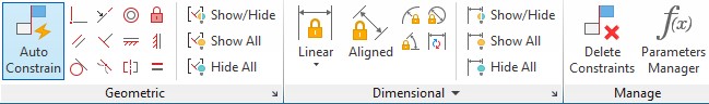
After drawn, you can also use dimensions and constrains to define how your shape is going to look like.
To draw a rectangle, I select the rectangle tool, click on place to start drawing, and then using the keyboard, I include the horizontal size, then press the “,” key to change for the vertical size, input this using the keyboard, and press enter to obtain the first rectangle.
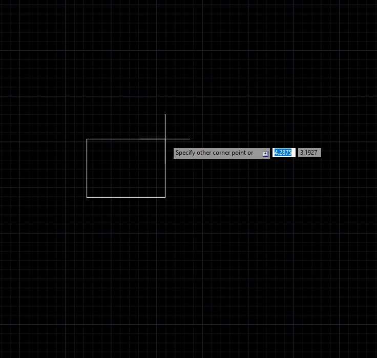
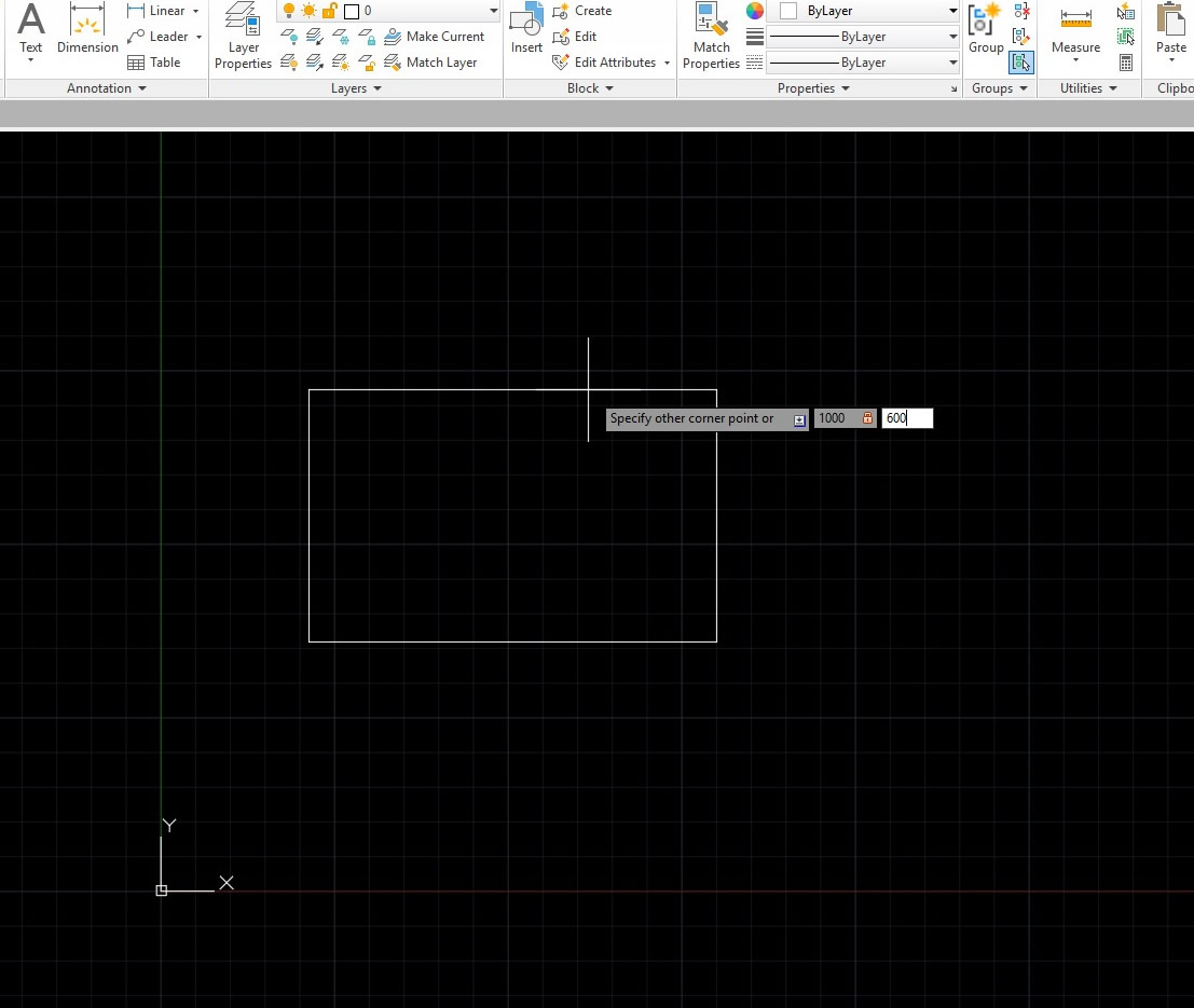
Here I just draw a rectangle, but all tools are very simple to use and you can easily create any shape you need. In the final project you can see how I design a complete mechanism using many different tools and editing tools.
#IRIS MECHANISM
To begin, I will start with the Iris mechanism. The Idea of this mechanism is to create a mechanism to keep a clue locked, and only when the participants decipher a code, they can take the lock of, operate the mechanism, and find the new clue. This puzzle required 2D CAD, which was done in AutoCAD, 3D modelling, Assembly and simulation, which was done in Solid works, and laser cutting for Fabrication.
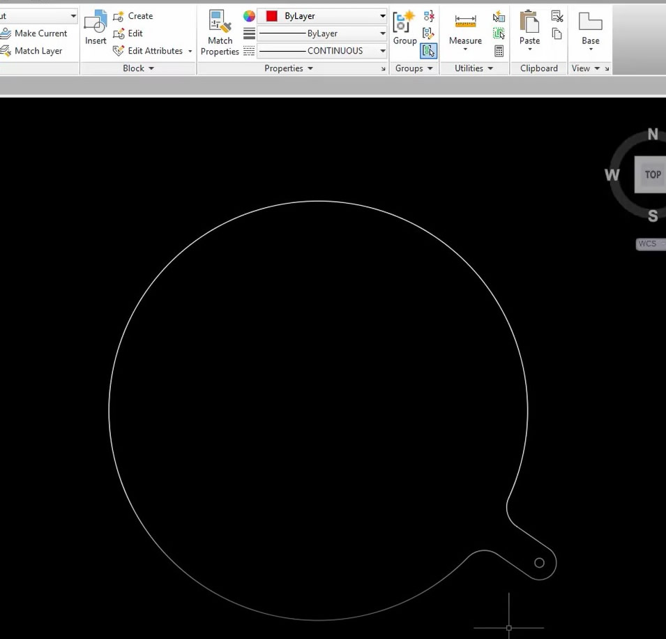
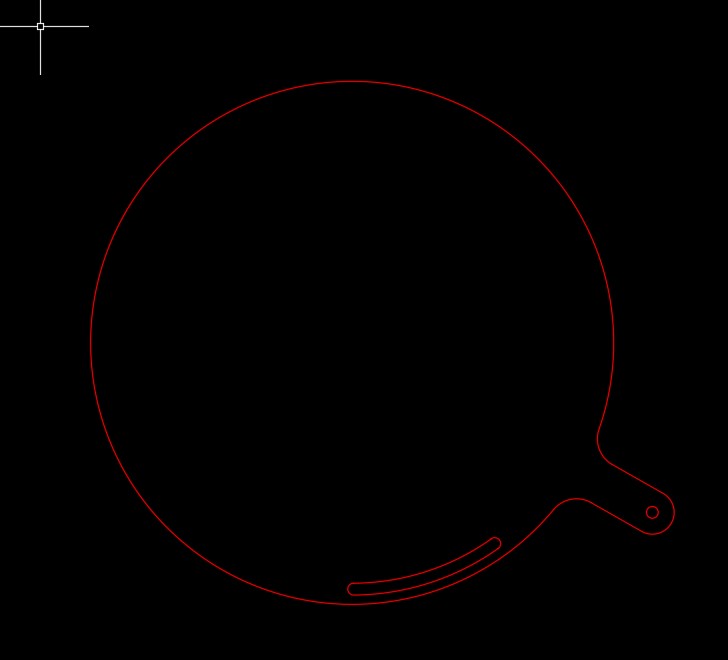
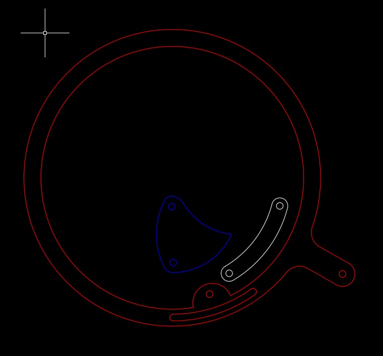
For design, I began with the static base. For this, I draw a circle with the radius of the size I needed, then a smaller circle outside for the handle, and connect them with straight lines. Then, trimmed the unwanted lines, added some fillets and a smaller circle for the lock to go in.
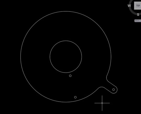
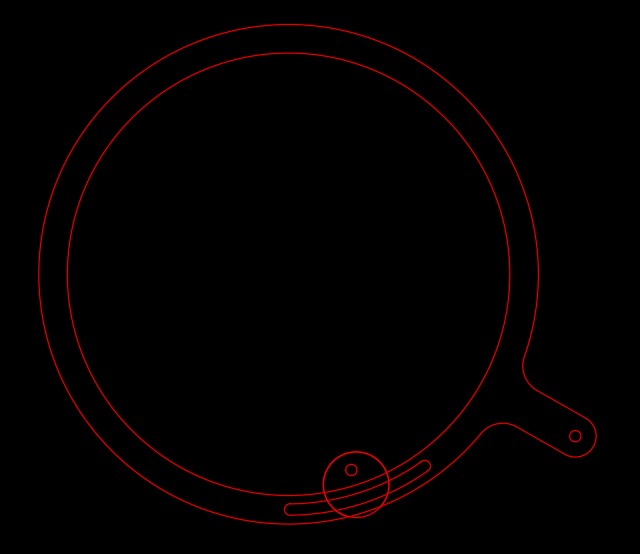
Next, I will draw an inner circle which will be the part of the iris to open and close. For the links, I will draw two circles 10mm from the inner and outer
border as shown below
. 
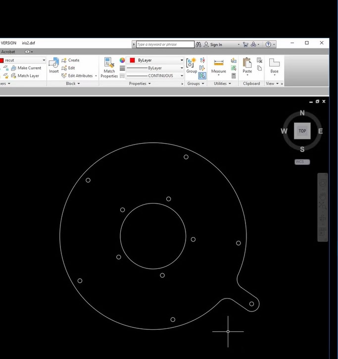
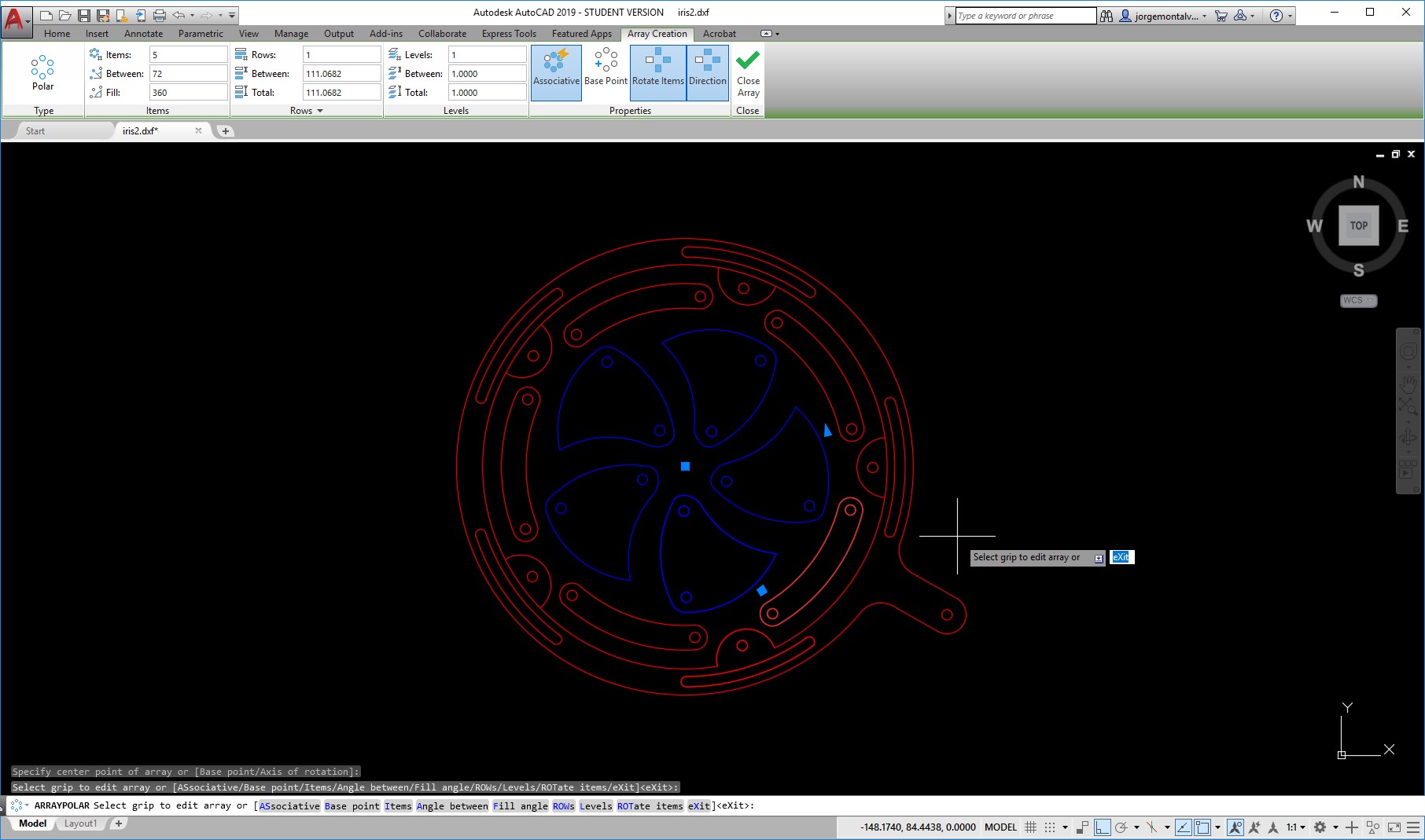
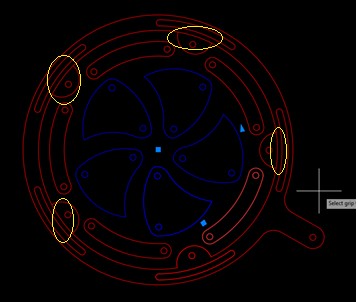
Next, because my mechanism will have 5 parts, I will do a polar array in order to replicate the two circles 5 times in equally distributed angles, as shown below.
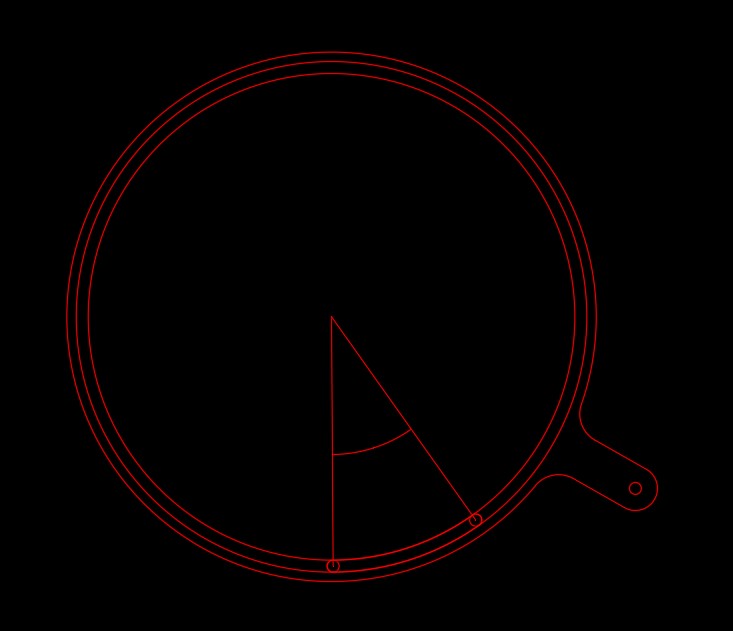
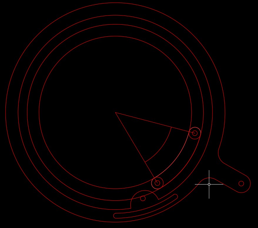
With This, my First part is done. Now, I need to do the moving mechanism. For this, I will create a moving base, with the same size as the fixed one, so I copied the outer outline of the circle with the handle. After this, I created 2 circles from the center to the inner and outer diameter of the small holes closer to the outside perimeter. The idea is to put some screws in the fix based, and the moving base will slide through a slot of the same diameter in moving part. Now, I will create a copy of the circle at 35 degrees from the original, as shown below
Now, I will trim the unwanted lines to keep just the slot.
Now, I will create a circle 20mm from the outside border. Additionally, I will draw a circle in the 12mm radius circle in the projection of the midpoint of the slot in the circle we just created, and a small circle in the space created, as shown below, and then, trim the unwanted lines.

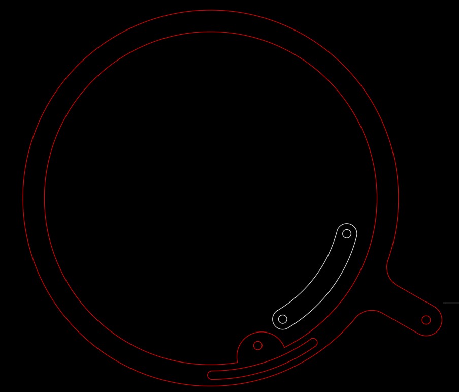
Now, I will create the link, whichi will just be repeating the same steps for the slot, but with 70 and 60 mm radius circles for the inner and outer profile, and 5mm circles 45 degrees apart for limits, as shown below. After this, just trim and leave only a single link, and draw a 5mm diameter circle in each corner, and change layer and color to indicate a new part.
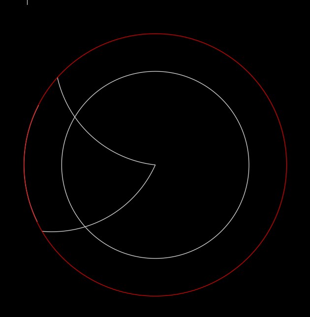
Now, we need to draw the closing parts. For this, I will copy the inner circle from the fixed part, and draw two lines at 75 degrees, as shown below. Then, I will create two arcs, from the center of the big circle to the point where the lines intersect the circle, as shown below, like drawing a shark tooth.
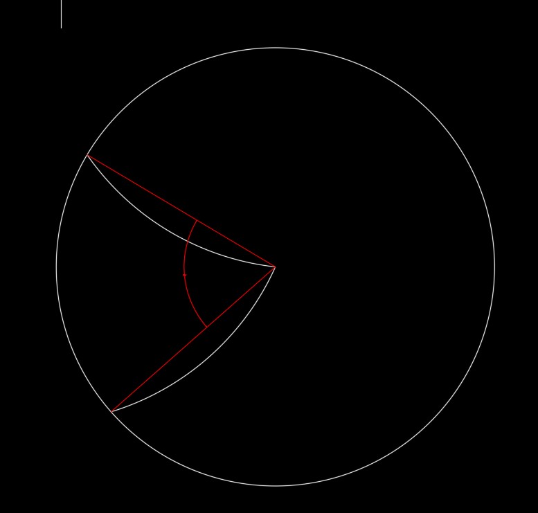
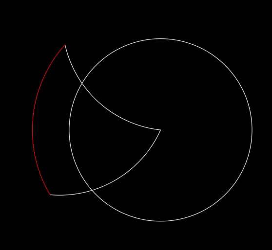
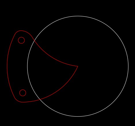
Now, I will create an offset of the circle at 12mm, and then extend the arcs until this circle, as shown below. After this, I will just trim the outside and leave the tooth, as shown, and finally, just add 5mm fillets on the sharp corners.

Now, we just need 2 circles for pivot, as shown below
Now, I will put the link and closing part in the center of the moving part, to then create a polar array of 5 instances, as shown below.
Now, just trim the small line between the 12mm radius circle and second perimeter circle, as shown below, and the design is done.
VIDEO IRIS DESIGN.
If this was the file I wanted to laser cut for example, I can just go to save as, and save it as a dxf file and im ready to cut, but as for this assigment, I need a 3d file, I will pass to a 3d software. To select a software for 3D computer aided design, I needed to use one that was easy to use, free, and didnt require a very powerfull computer. This is the reason why I selected Autodesk Inventor, as my computer was able to run it, it has a free academic version for students and its fairly simple to use, as its 2d drawings are similiar to autocad, which I had used before.
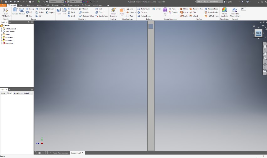
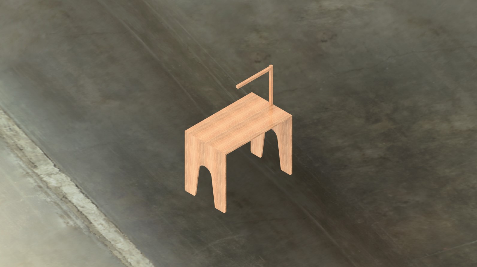
As a first step begin shaping my final project, I created a possible shape of my design. In the software, you have the option to create either a part or an assembly. I will begin with a part, just to see how my project could look like and verify the dimensions.
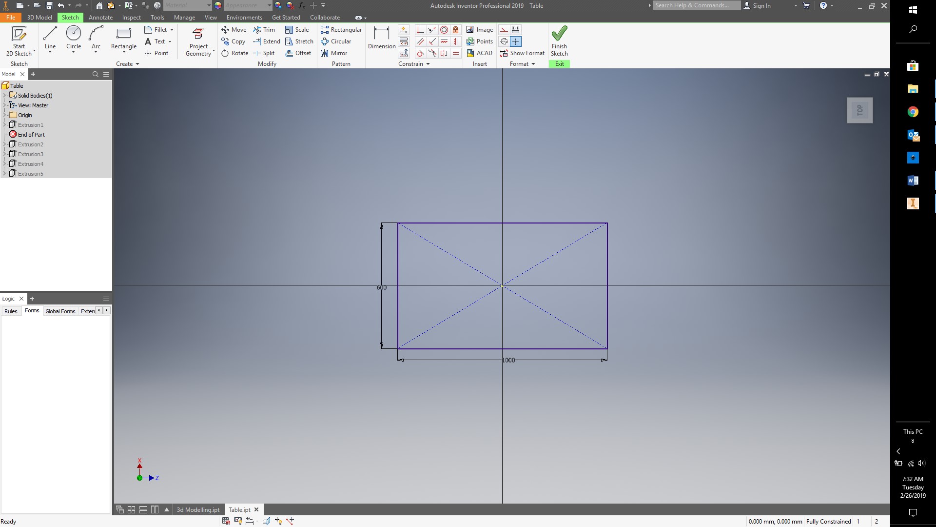
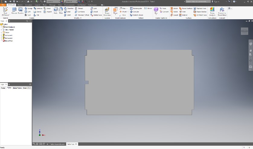
I begin with the working area of my smart desk, which will be 1m x0.6 m.
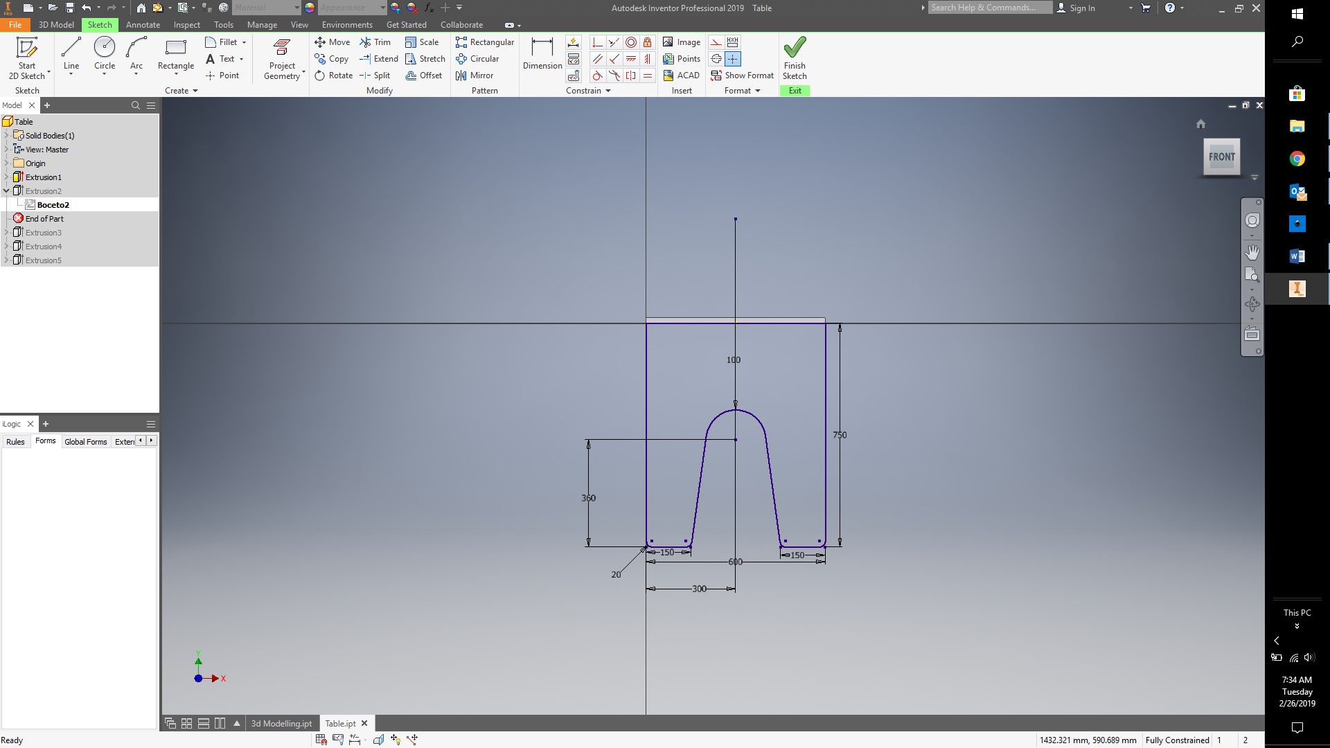
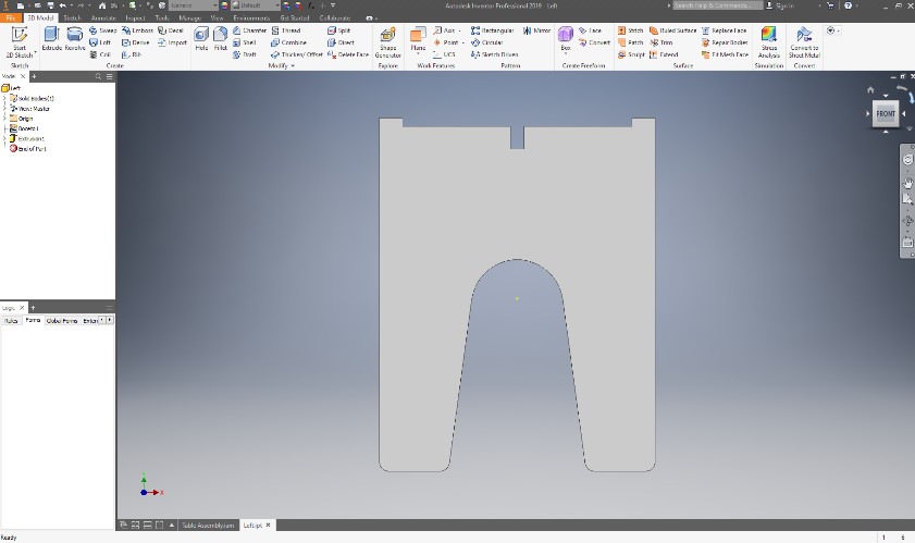
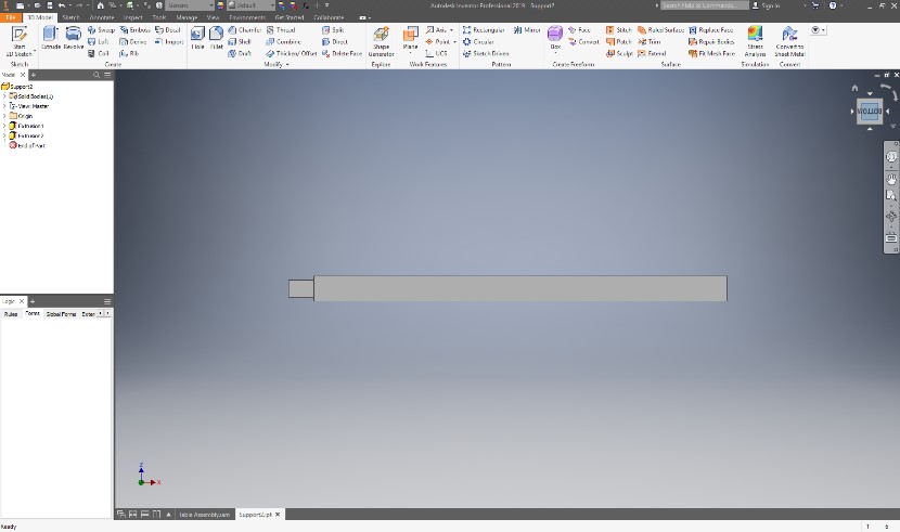
After extuding, I draw the legs, and then mirror them to have both sides. Finally, I create two extrusions for the support for the camera itself.
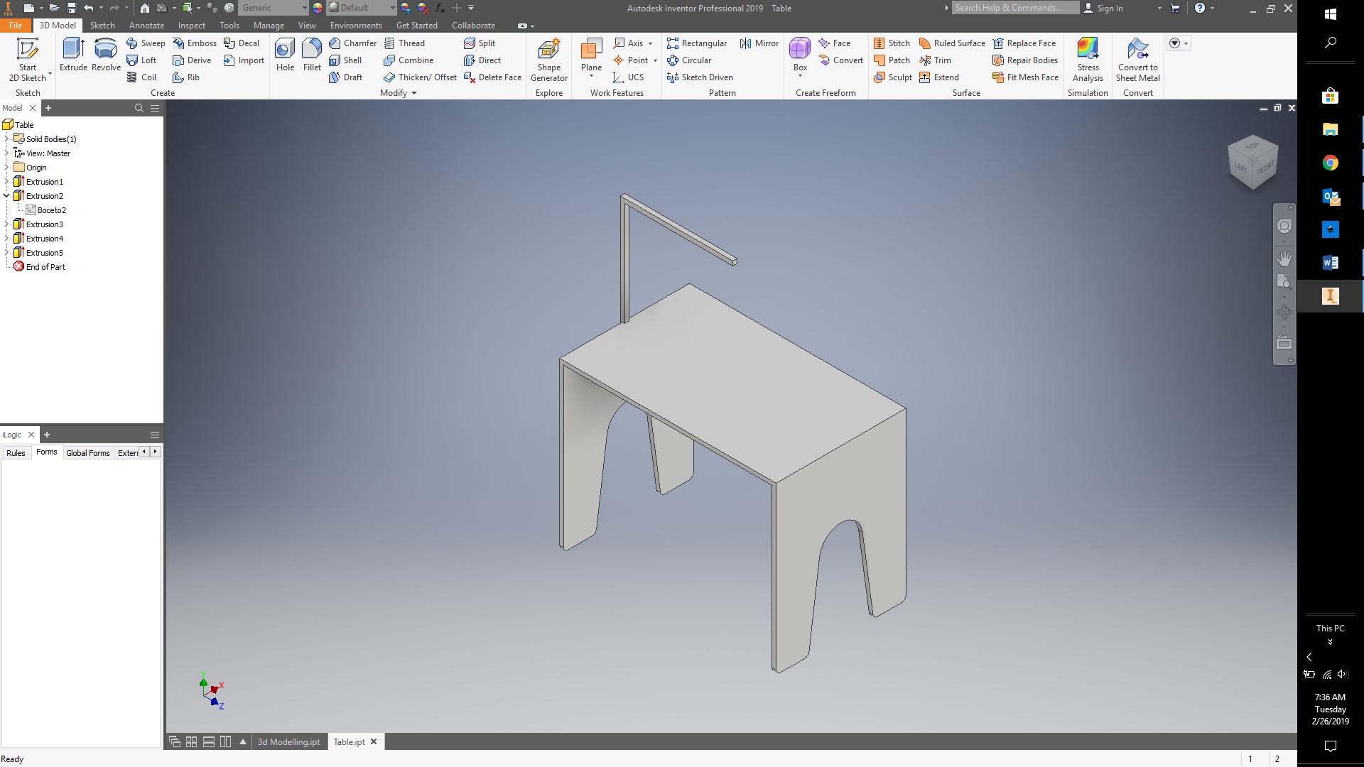
This model works just as an initial prototype to verify measurements and start shaping my project, and if I want to build it, I could 3d print it or use a software like slicer to test it out. To really build it, I need to create one as an assembly, where each side is an individual part that would snap fit in place.
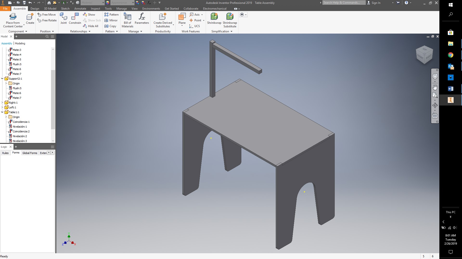
After creating the individual parts, I can create an assembly to see my final Cad model for my project.
If I create a drawing from my parts, I can save it like a DXF file, and delete the frame in order to only cut my parts in the laser cutter. The DXF file can be open in any vectorial software like AutoCAD.
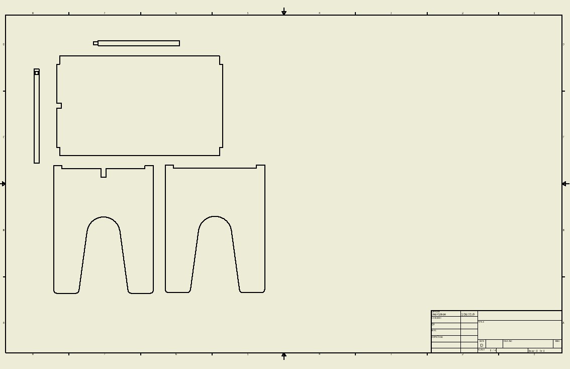
This would be a vector drawing for my project, which means that the shapes are defined by coordinates in space and even after zooming in, the line would be a line. A raster image is an image defined by pixels, which means that when you zoom into it, the image would be blurry if you don't change the pixels.
If you see this picture, this is a render of the model, which would be a raster image because the image is represented by pixels, but if you zoom in, you would actually see the blurry.
This is a close up of the corner of the desk, and as can be clearly seen, the image is blurry as each dot represents a pixel.

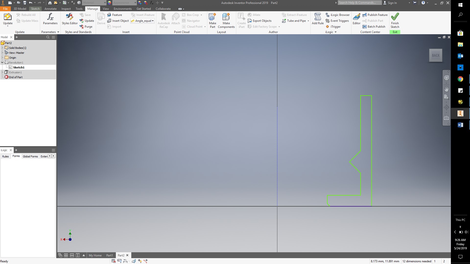
For this puzzle, I will create a parametric CAD to be able to adjust to any type of bottle. To start, I will use autodesk Inventor. I create a new part file, and then draw a sketch on the front plane using lines, as shown below.
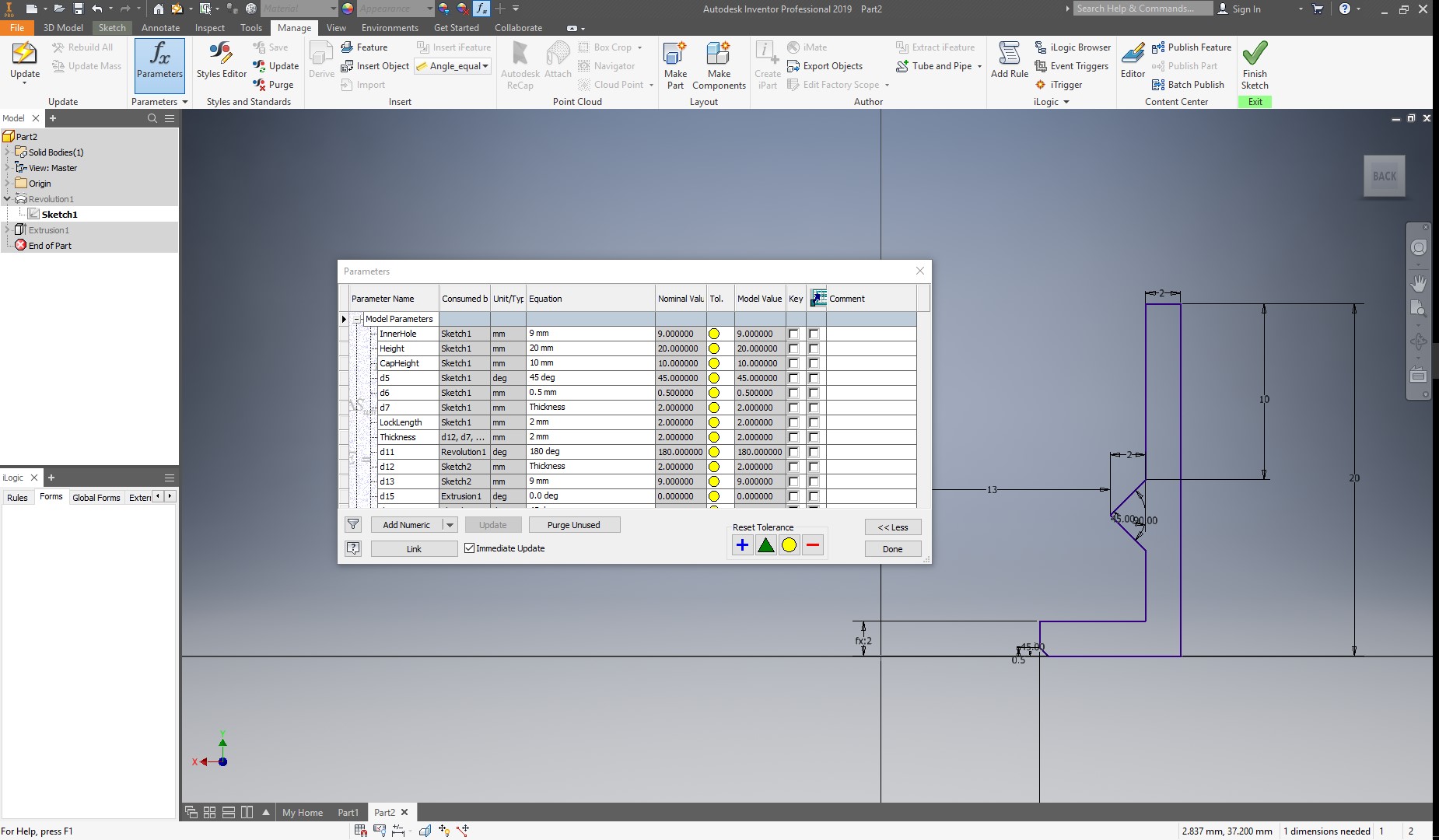
When adding dimentions, I will create my parameters by given them a name, and then using the equal sign to assign a value.
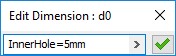
After adding all the dimension for this sketch, I created the following parameters:
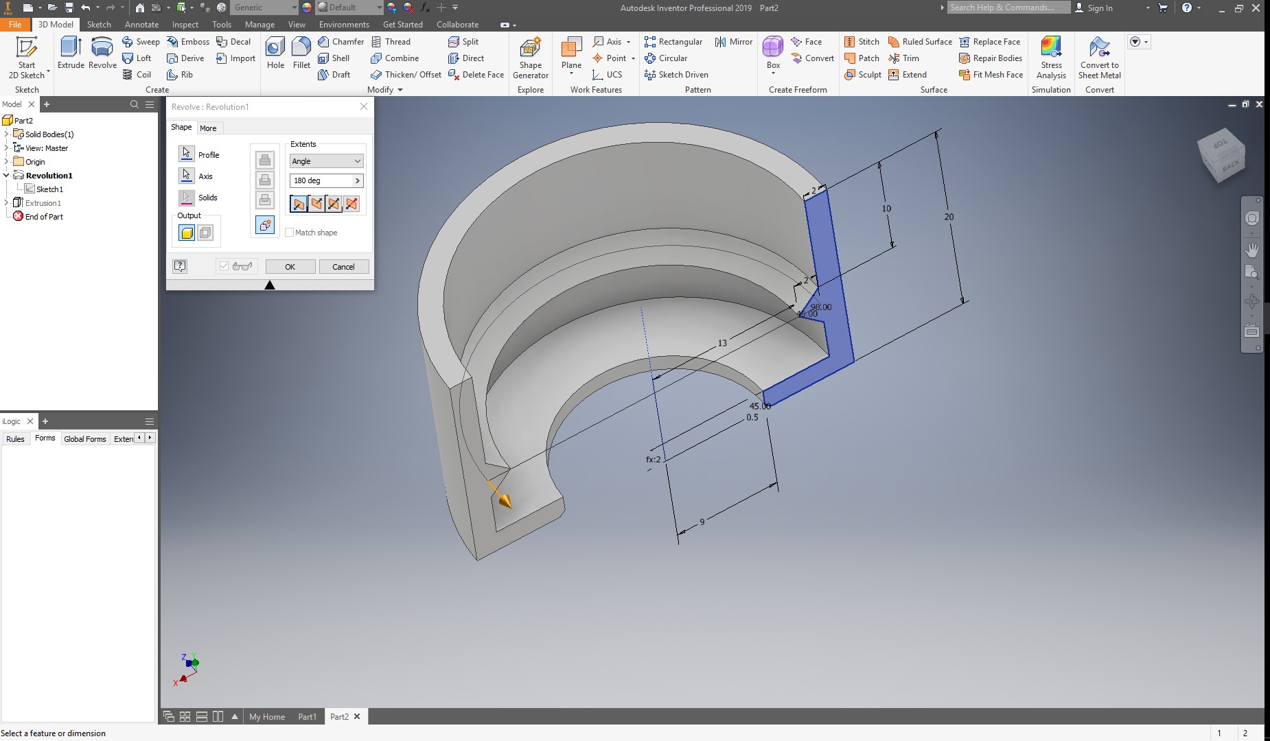
If I change my parameters, the sketch will automatically update. Now, I will begin with the 3d design. For this, I will make a 180 degrees revolution as shown below:
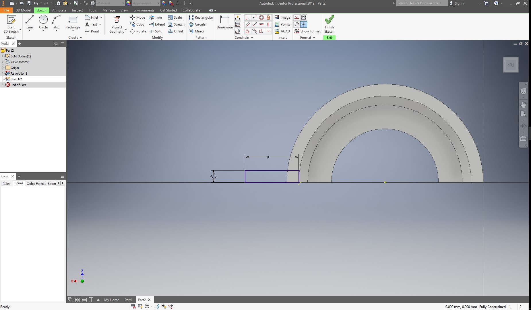
Next, I will create a rectangle in the top profile, and adjust the height to the thickness parameter, and give it a width of 9mm as shown below:
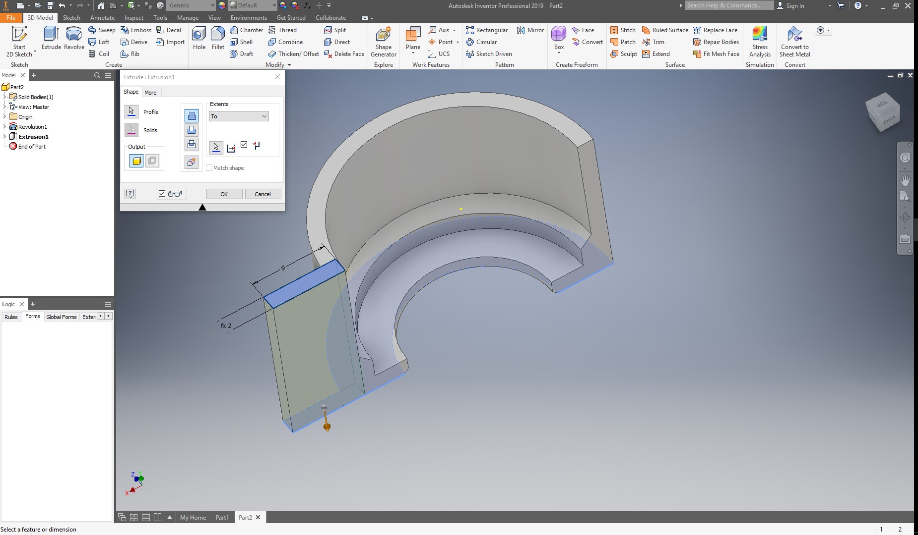
Next, I extrude this rectangle until the end of my solid.
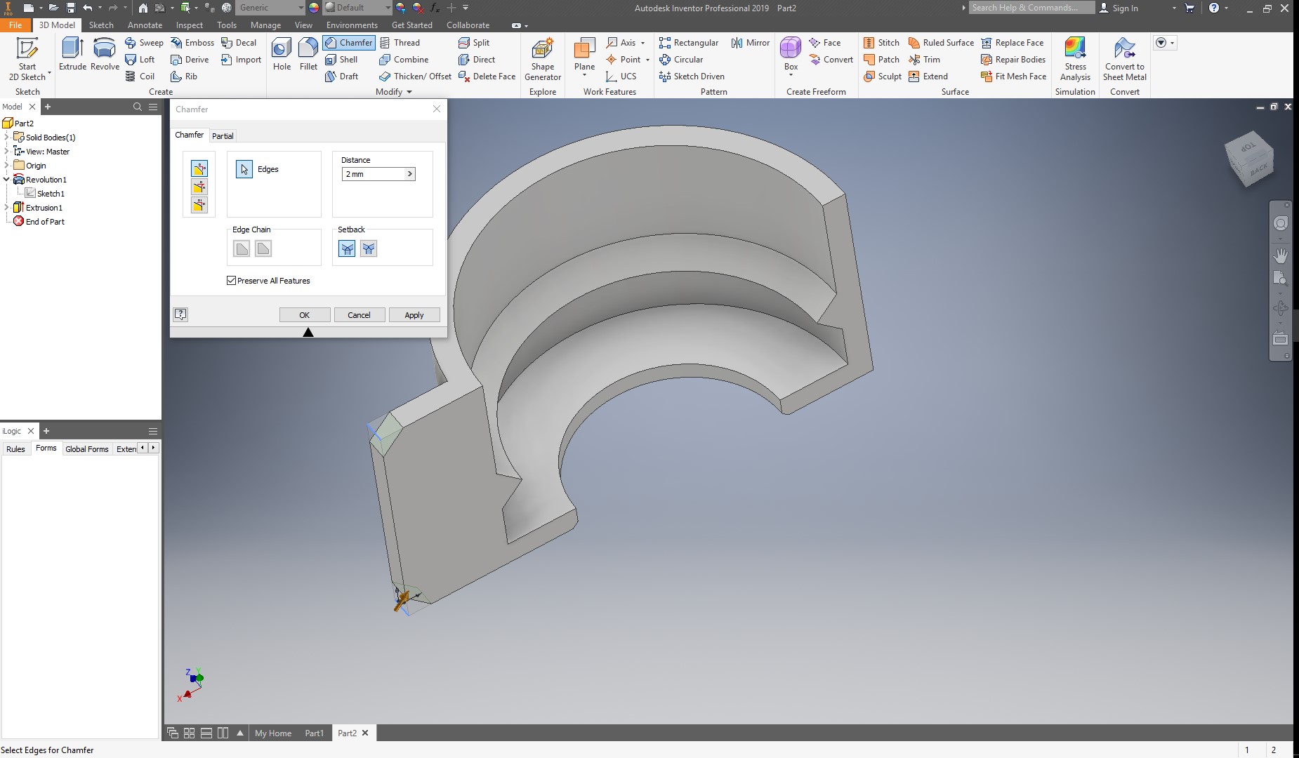
Now, I add two chamfers, to prevent sharp corners.
And create a circle for the lock to be placed.
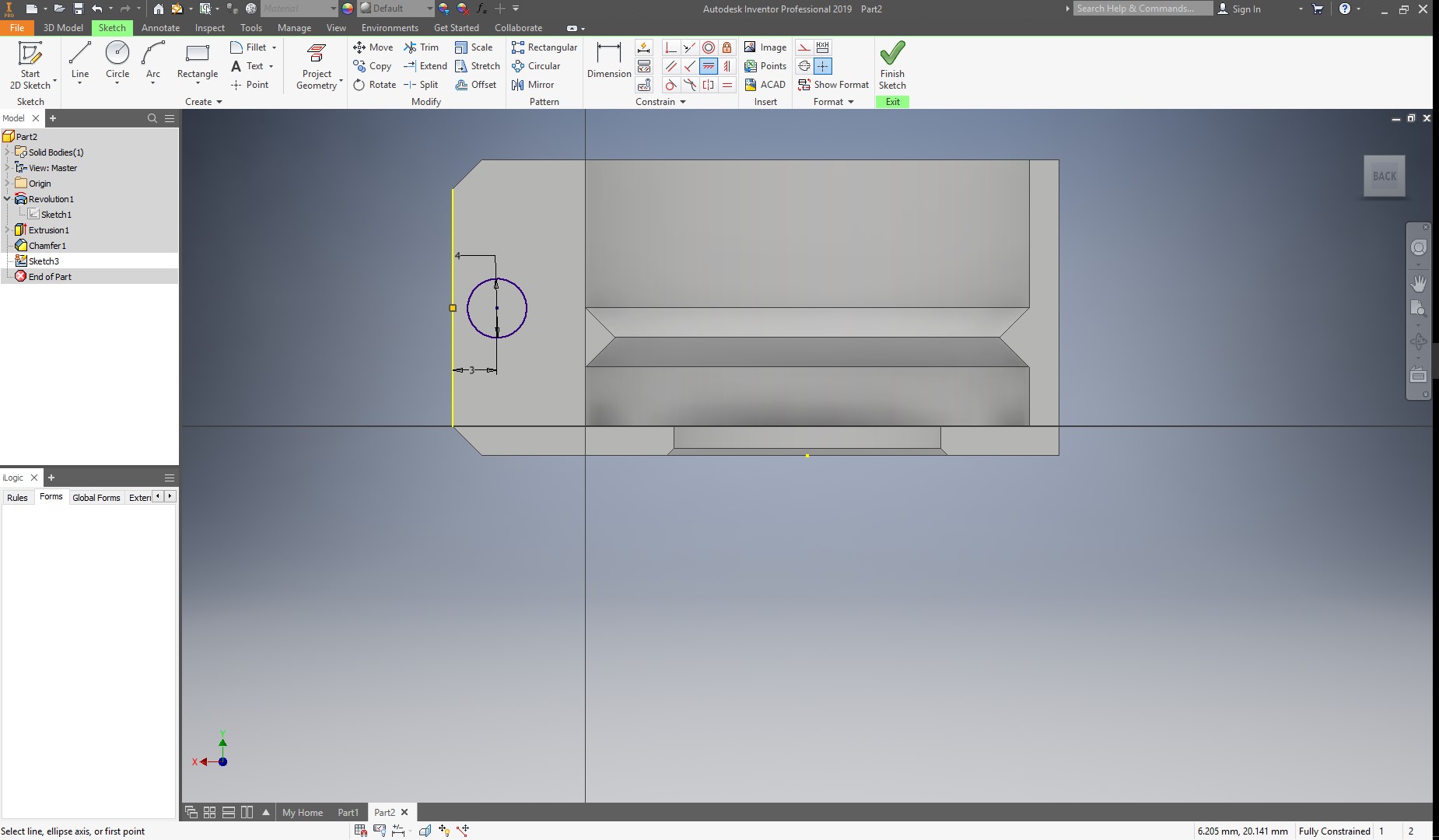
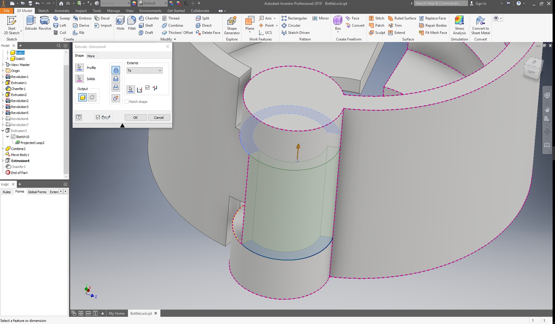
I extrude my lock as a cut, and in extents, I select All.
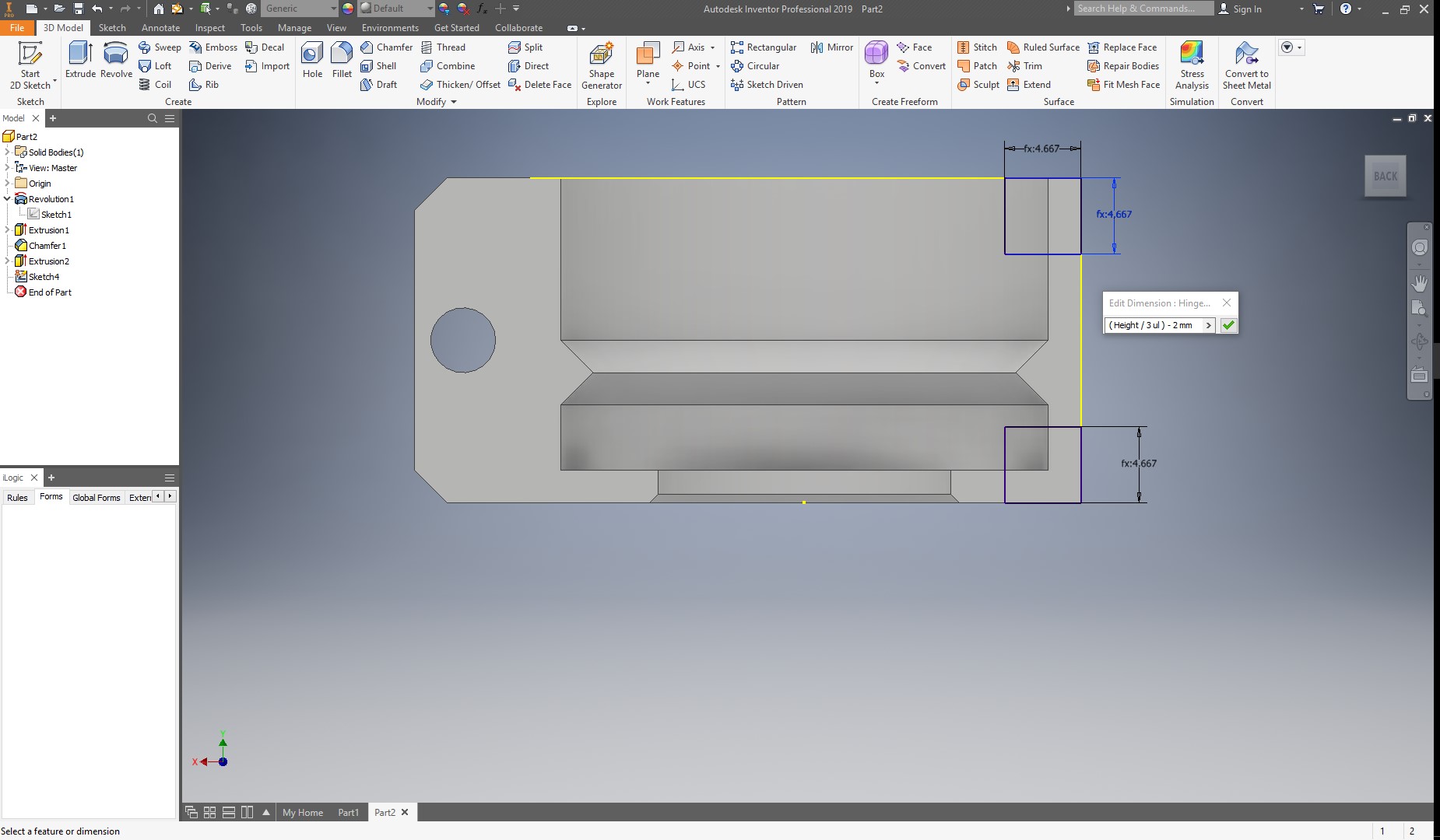
Now, I will create the first part of the hinges, For this, I will create two rectangles in the other end of the ock, and link them to the height of the bottle, so when I change the height, this values also change. I will make this rectangles 1/3 of the Height, and then substract 2 mm for tolerance. I make this for all the sides of the rectangles.
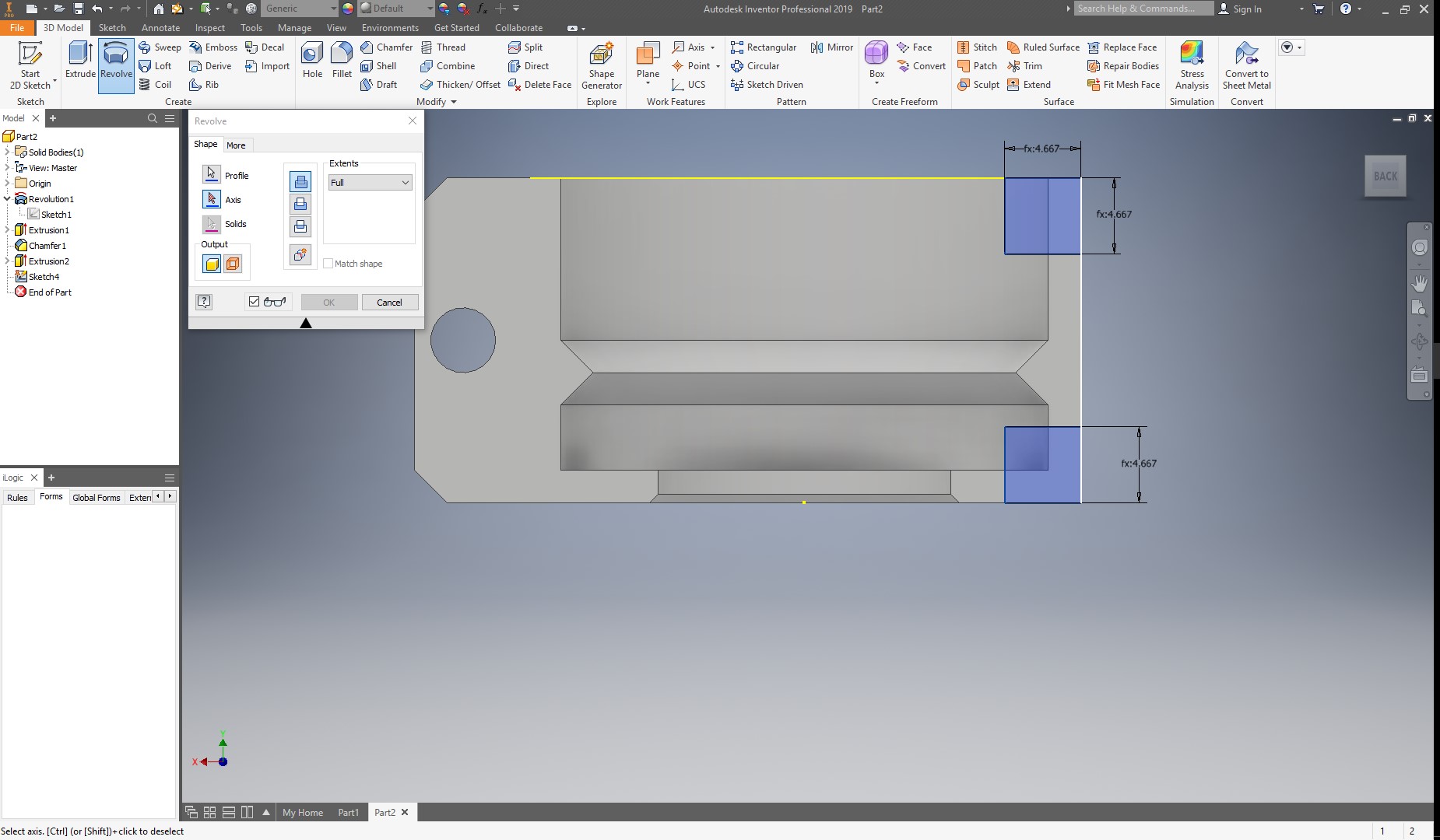
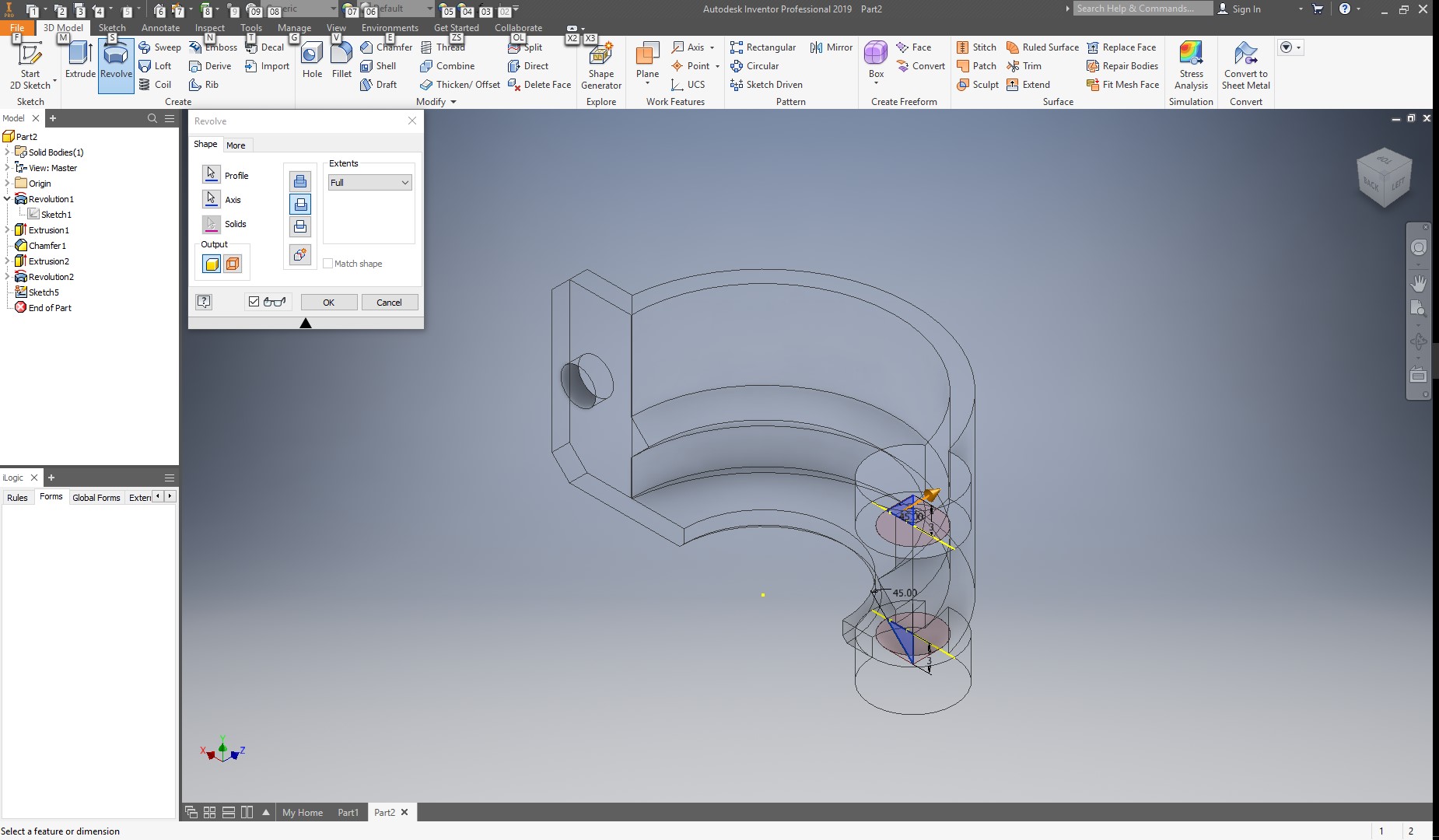
And then make a FULL 360 revolution using the line more to the right as an axis, as shown below.
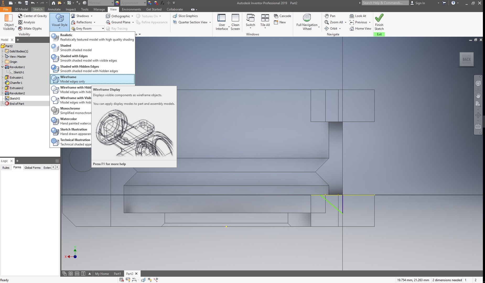
Now, to create the hole for the other part of the hinge, I go to the view menu and change the visual style to wireframe, to be able to look inside my part easier, and then draw a 3mm line in the middle of the last revolution, and then a 45 degree diagonal and a horizontal line to close the sketch,as shown below.
Now, I will make a revolve operation, but this time, removing material.
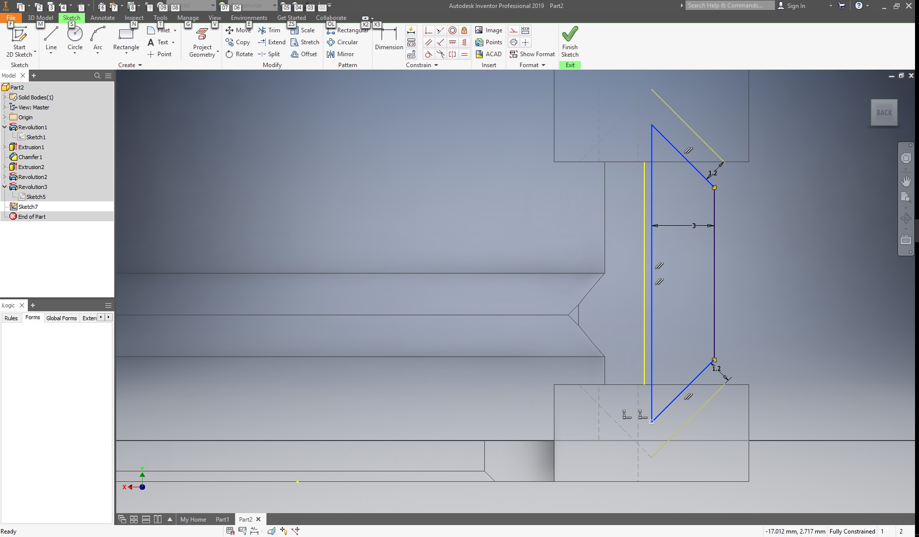
With this, I’m done with the first half of the lock.Now I will create another sketch on the front plane, and this time, I will draw a trapezoid as shown below:
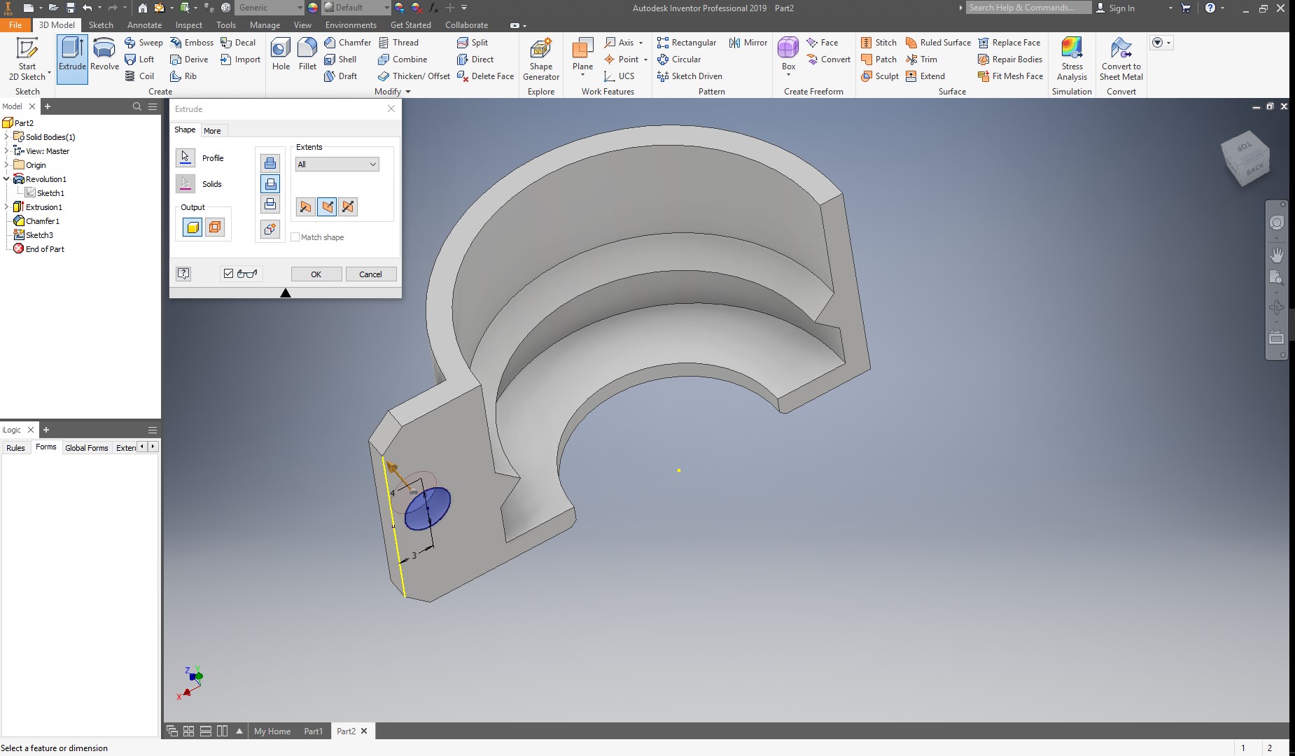
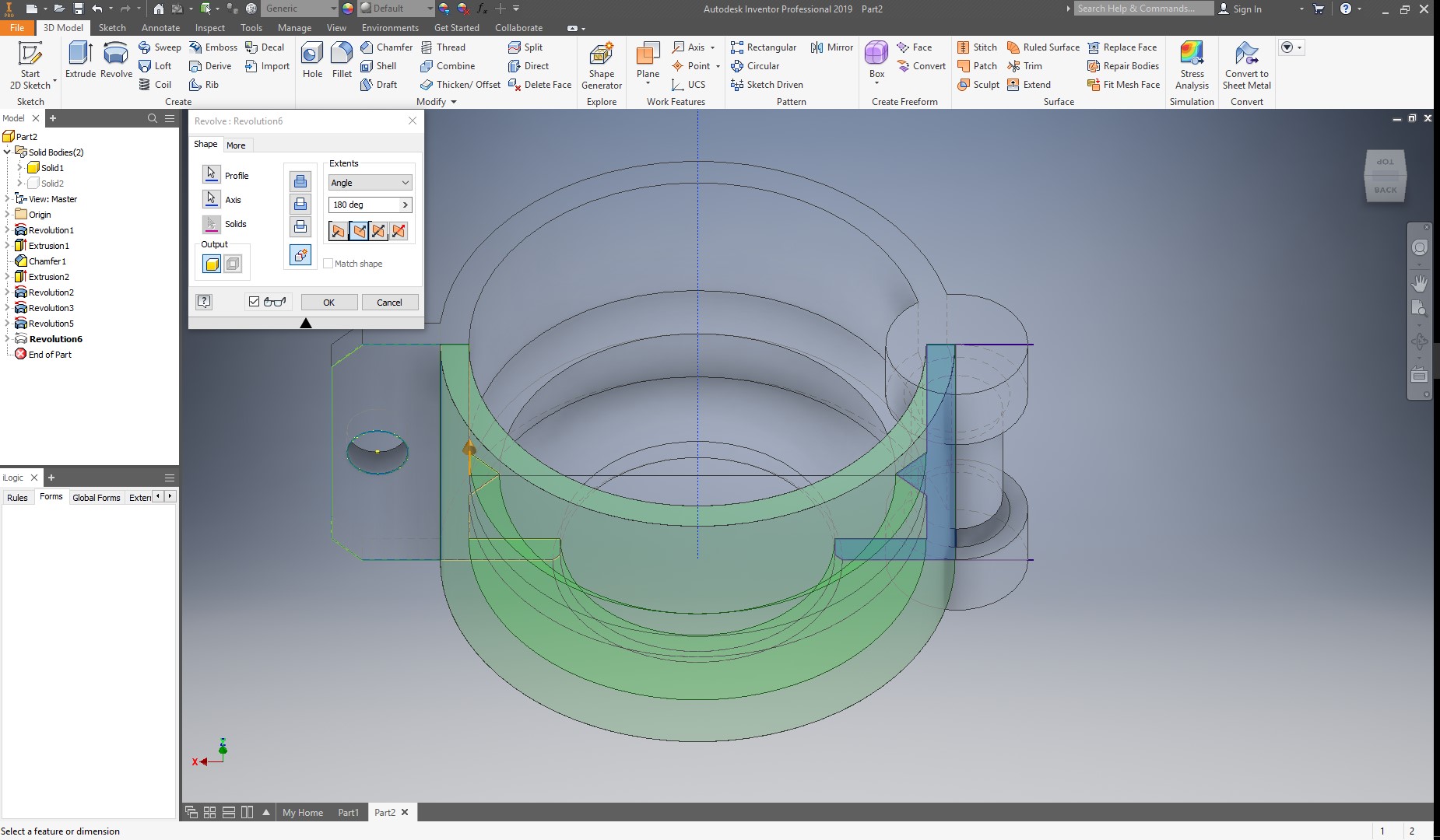
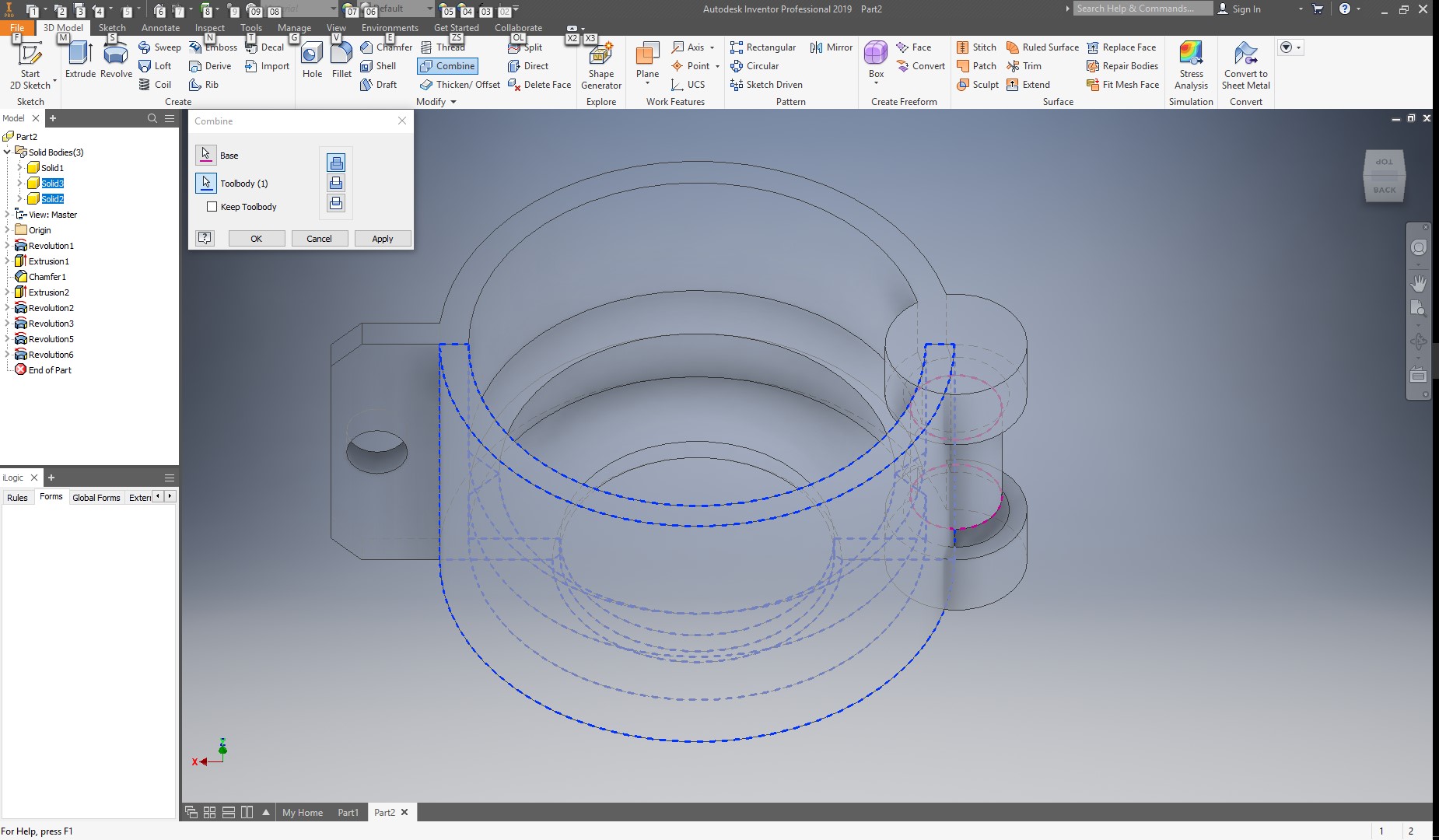
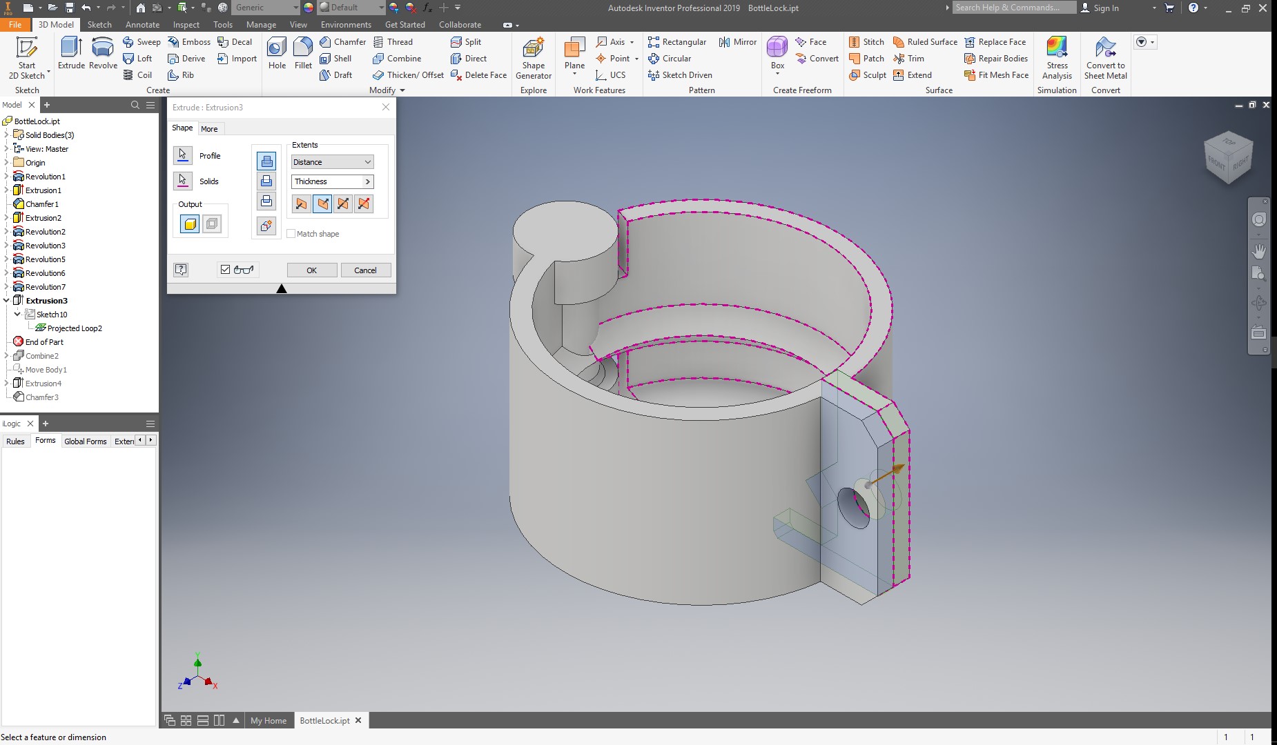
Thistime, I will revolve the part trapezoid through the line in the center, but making sure to select the ![]() new solid button, as this will be the second part of my lock. Now, I will again revolve the first sketch, but also as a new solid, and in the other direction, to create the other half, as shown below:
new solid button, as this will be the second part of my lock. Now, I will again revolve the first sketch, but also as a new solid, and in the other direction, to create the other half, as shown below:
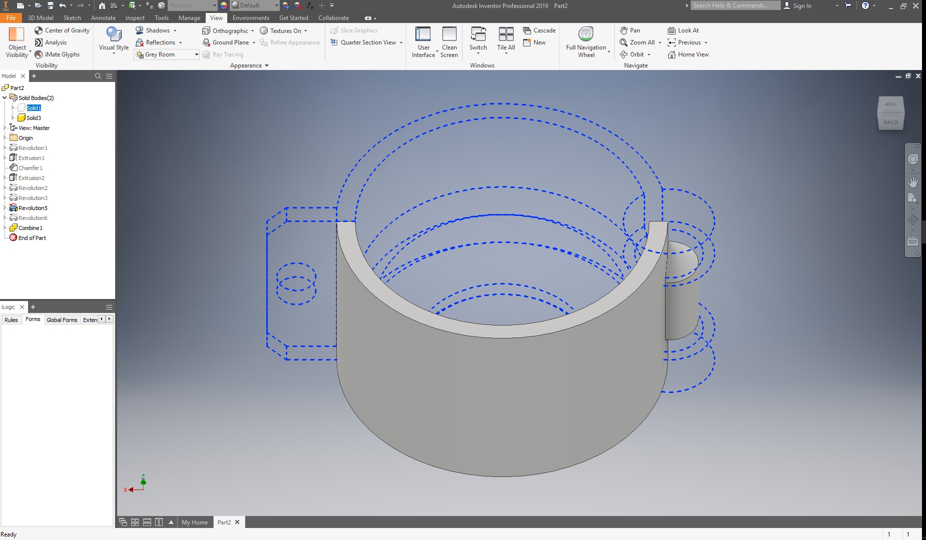
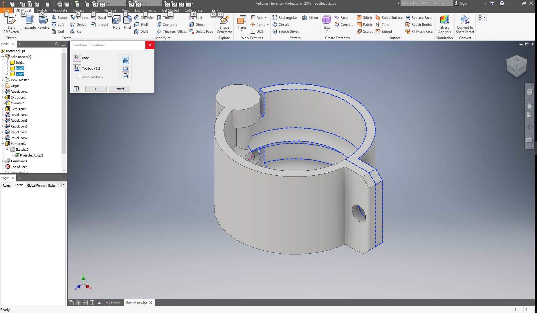
To join the last 2 parts into a single solid, I will use the combine tool in the 3d modelling toolbar, in the modify section, and I select parts 2 and 3 to be merged.
I can select a solid from the solid bodies folder in the Model Menu, and right click and disable its visibility.
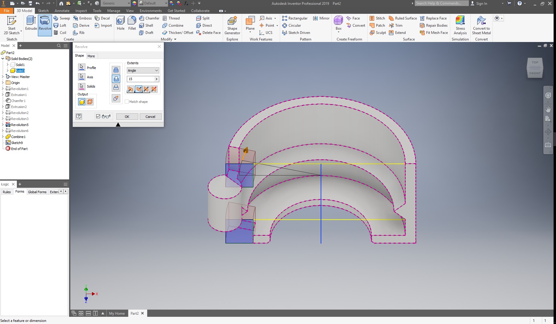
Now, I will draw again the 2 rectangles, but this time, I will remove material in a revolve operation, but only for a few degress. As this will be a parametric part that will change its value, I will make this operation to change if the height changes, and the value of this revolution will be 1/6th of the height.
Now, I can project the rectangle and circle of the lock In the first half to another sketch in the front plane, to extrude it again but for the second half.
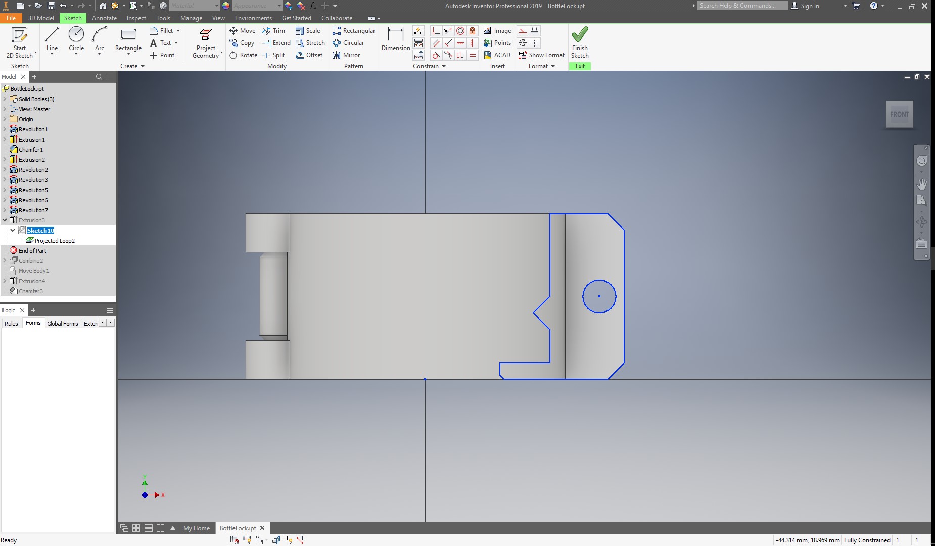
I will extrude this with the same thickness parameter, and also create it as a new solid.
Now, in have to combine again this solid to the second solid.
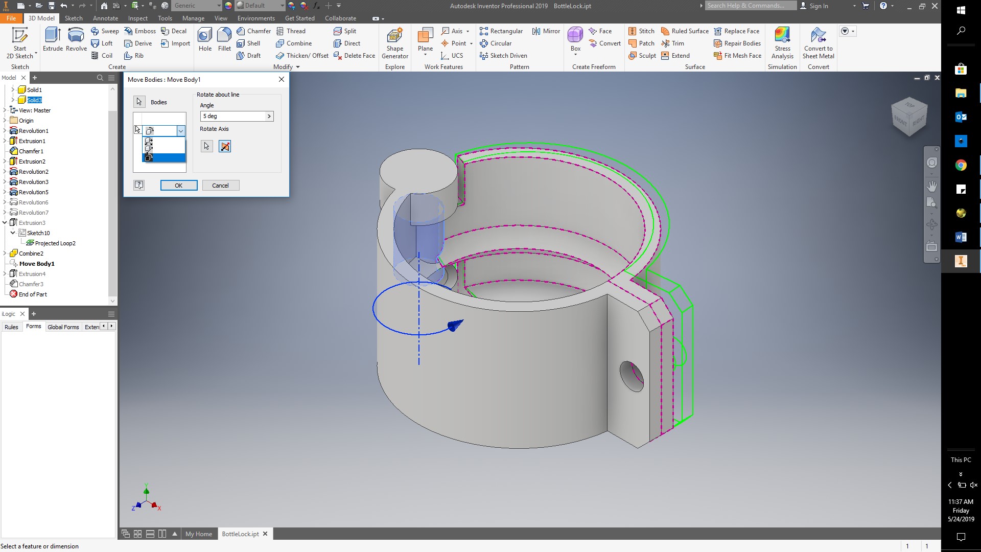
Now, in order to be able to print in place my lock as an assembled mechanism, I will rotate the second solid using the move bodies command in the modify section of the 3d modelling toolbar. Here, I have to click on the drop down menu to change from moving to rotation, and then select the cylinder axis as the rotation axis, and I will just rotate it 5 degrees, as shown below.
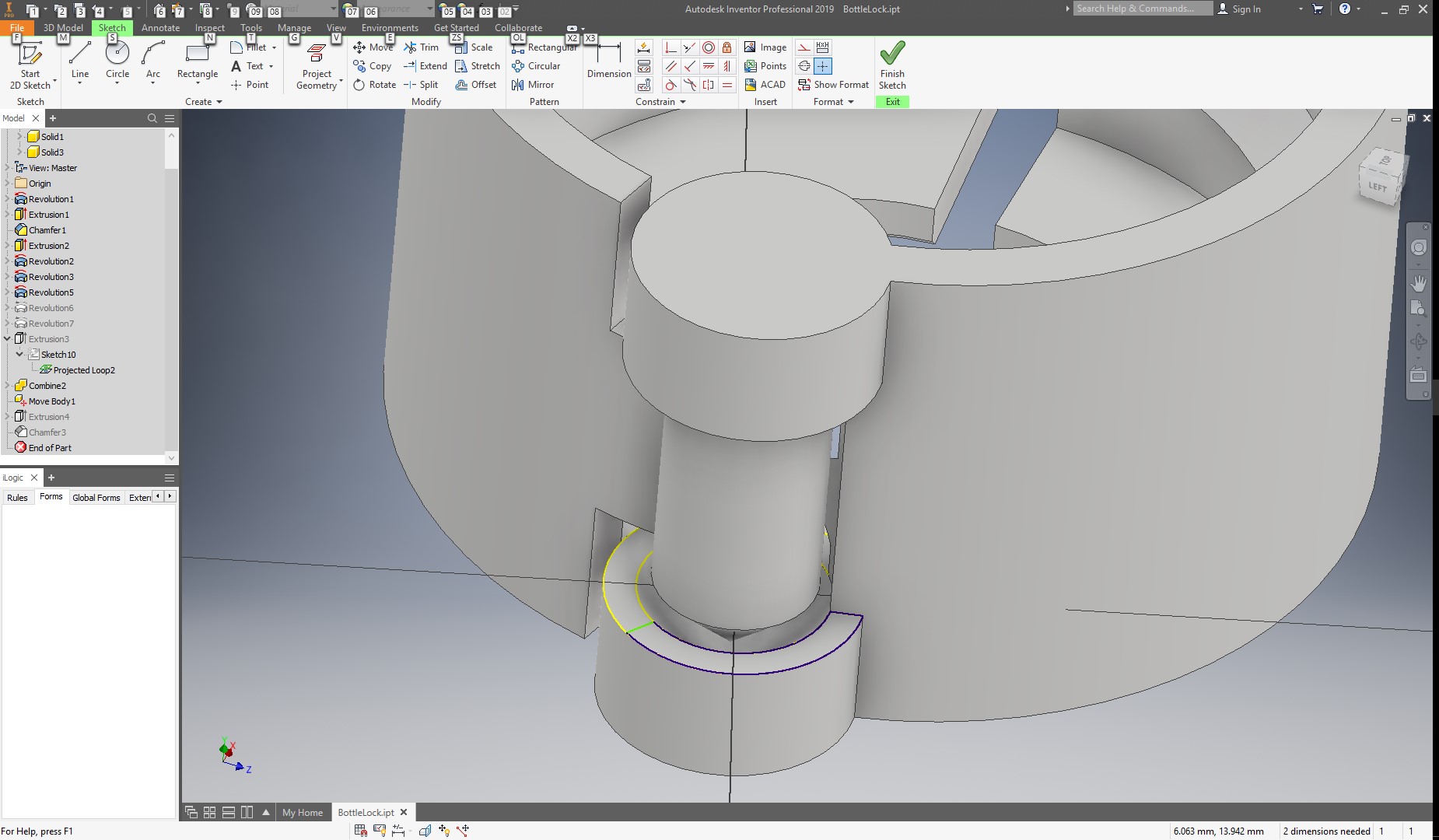
Finally, I will create a sketch on my first solid hinge, and draw the arcs over the hinge and close it with a line, in order to cover my hinge.
And extrude until the top.
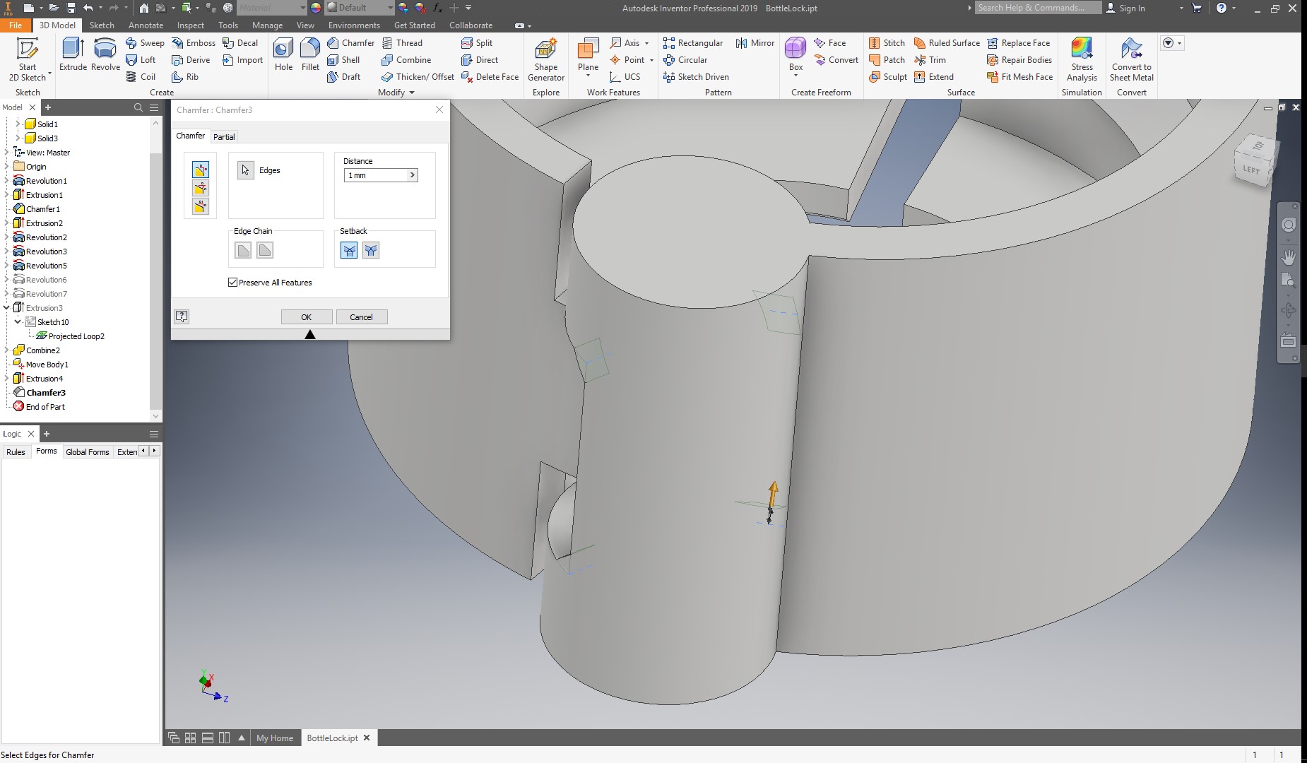
Finally, I can create a small chamfer to the 4 corners of the hinge, as shown below:
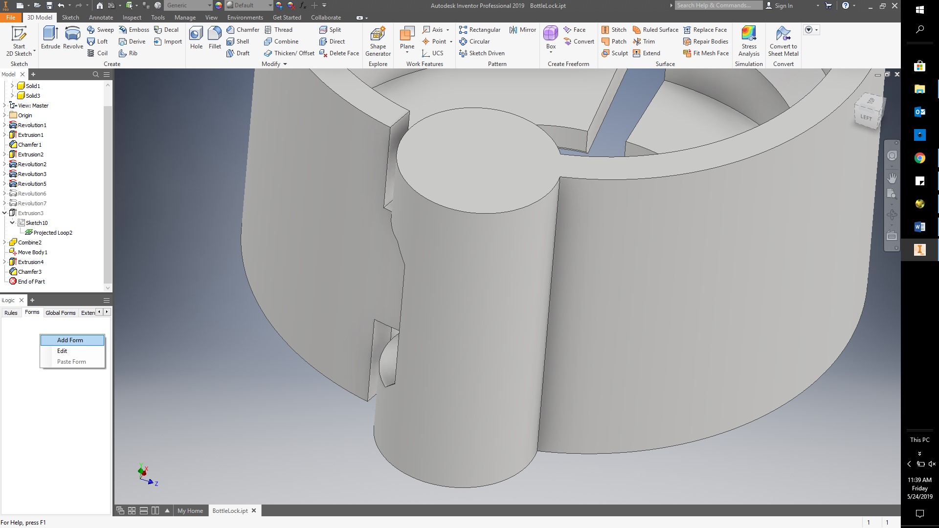
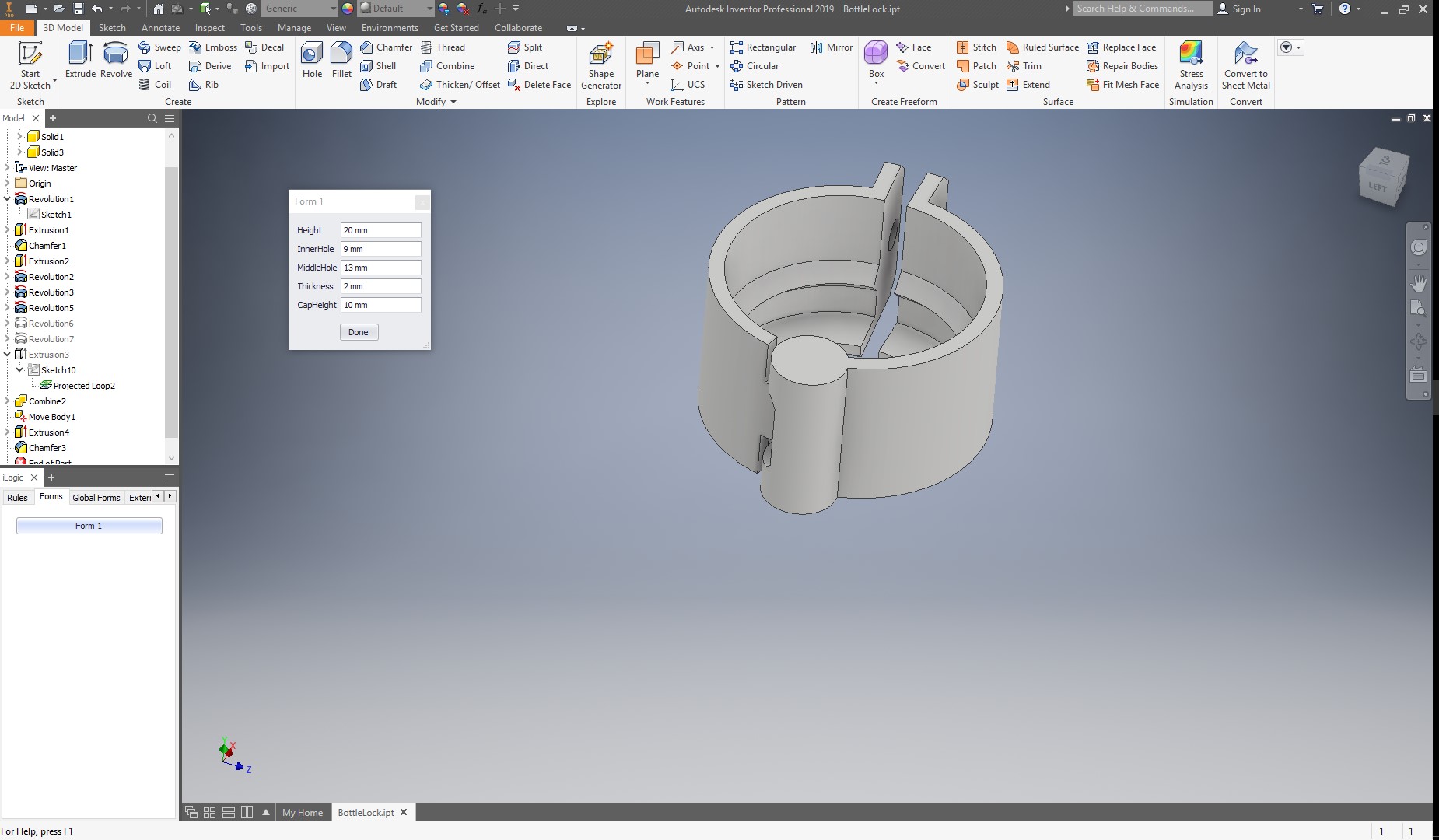
Now, My 3d model is ready. Now, I will create a form to be able to easily change my parameters. For this, I go to the view toolbar and make sure that the illogic menu is on in the user interface, and then, go the forms tab and right click and select “add form” as shown below:
Now, I just drag and drop the parameters I want to have in the form.
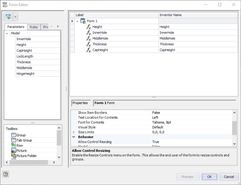
And after accepting, a menu will appear with all my parameters, and if I change any value, I can see how my 3d model updates immediately.
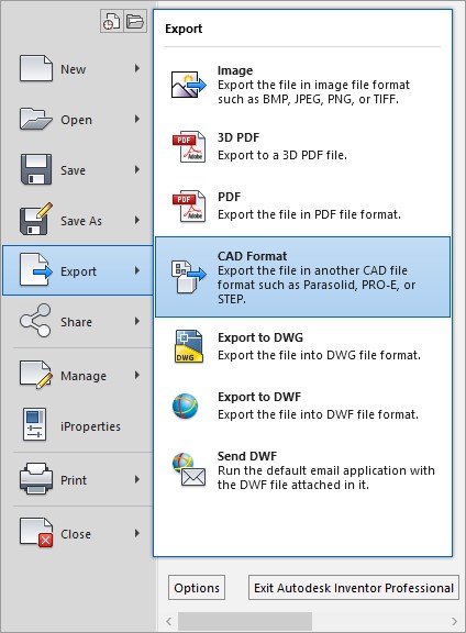
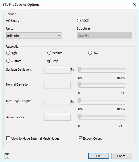
Now, Im ready to print my part. For this, I just have to save as an stl. For this, I will go to the menu, then click on export, and save as Cad Format. On the file type drop down menu, I select stl, and in the options menu, I make sure to change the units to mm, to make sure the file doesn’t change size.
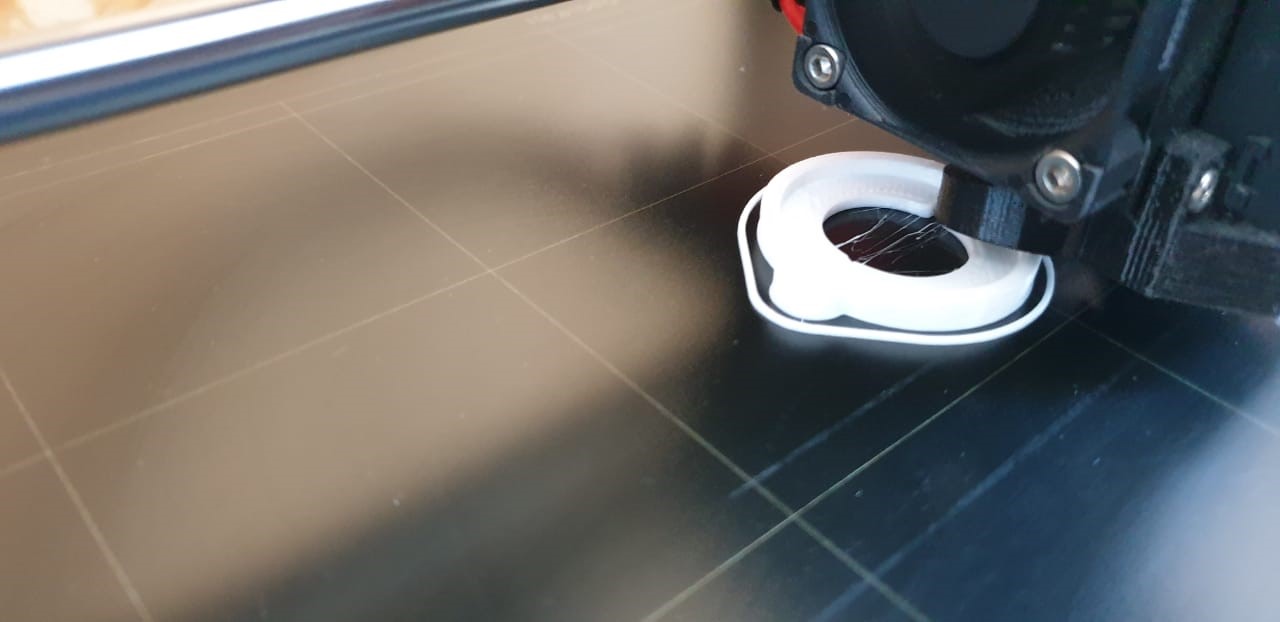
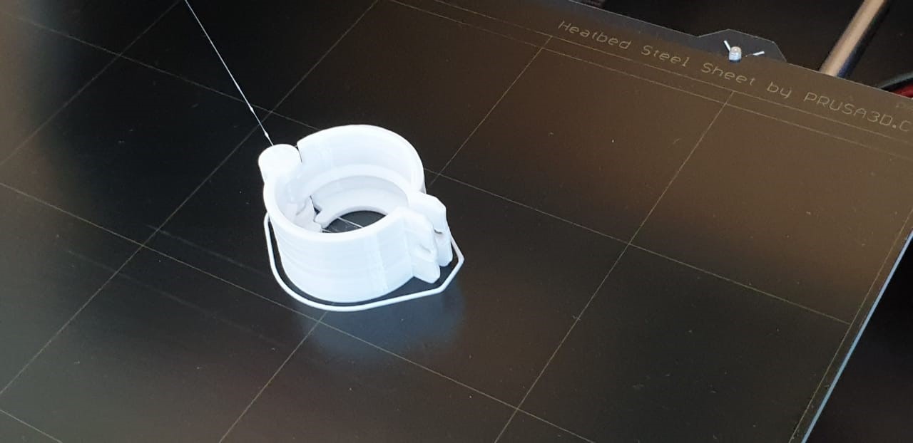
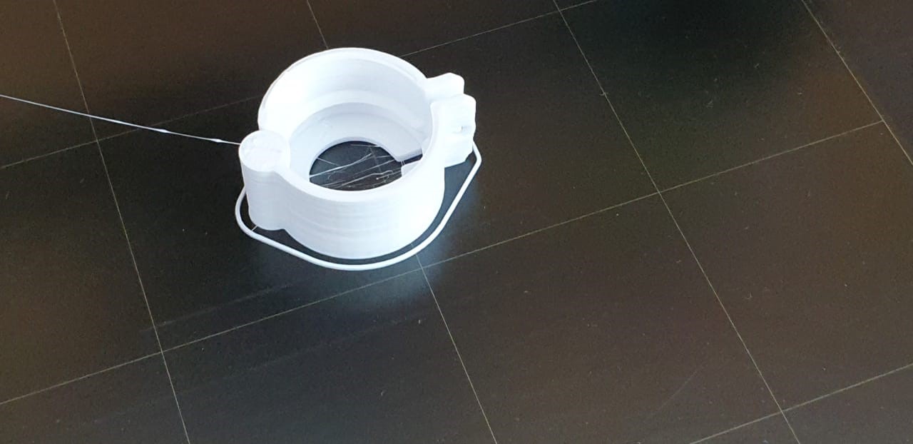
Now, I have my STL and I’m ready to print. After slicing the file at 0.1mm and 10% infill, I sent to print in our prusa mk3.