Networking and Communications
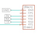
For this week, I will explore networking and communications between my pc and the boards. For this, I will use my boards created using satcha-kit, but in the meanwhile, I tried them with Arduino. My first test is to connect the following components.
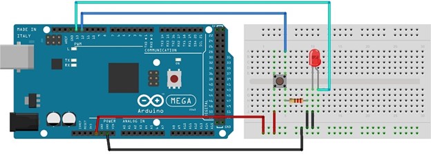
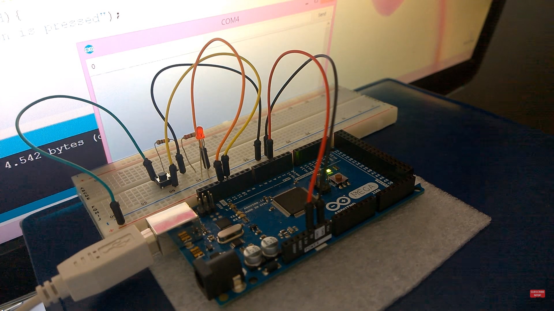
My assembly should looked something like this:
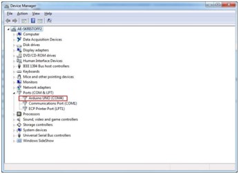
Now, I connect my Arduino to the PC and select the specific COM port and board type.
When you upload a file to the arduino, you are actually comunicating with it via serial port. As an example, I opened the blink example and upload it to the arduino. While uploading, the tx and rx start blinking, confirming that the communication is in progress. TX will blink everytime the arduino is transmitting data to the computer, and the RX will blink everytime the arduino is receiving data.
Now lets setup the communication between the PC and the arduino. First, we need to setup the pins that we are going to use. Notice that the cable that goes from the LED to the arduino is connected to port 13, and the cable from the push button to the arduino goes to pin 12. So the first lines indicated this:
int led = 13; //Tell arduino the cable connected in port 13 will be a LED
int button = 12; //Tell arduino the cable connected in port 12 will be a button
Now, I must tell the arduino that the LED pin will be used as an output because we want to turn the LED on and OFF, and that the Button pin will be an input because we want to know when the button has been pressed. For this, we should use a setup method, that has the following structure.
void setup(void) {
pinMode(led, OUTPUT); //define the port 13 as an output
pinMode(button, INPUT); //define the port 12 as an input
}
Now, lets add a line in the setup to tell the arduino that we are going to be using serial communication.
void setup(void) {
pinMode(led, OUTPUT); //define the port 13 as an output
pinMode(button, INPUT); //define the port 12 as an input
Serial.begin(9600); //INITIALIZE THE COMMUNICATION
}
The 9600 number in the parenthesis is also known as the Baud Rate. This is the speed at which the communication will happen, and if it is not set correctly, the communication will occur, but the messages will not be received correctly. Think about it as if somebody was speaking to you at a different language. You can hear them, but you could not understand the message. It is very important that your computer and Arduino speak the same language, and a 9600 baud rate is used by default.
Now, let us configure the communication. The first thing I will check if is the communication line is available. We do this using the serial.available() method. If the serial line is not being use, we could use it. If it’s being used, the loop will repeat itself waiting for it to be available.
void loop(){
if(Serial.available() > 0) {
//Anything you put here, will be executed if the communication line is available
}
}
To read information from the serial communication, we use the Serial.read() method. We create a variable called ledState which is going to be a Character, and save the information there in order to be able to use it later. '
char ledState = Serial.read();
Now, I need to see what message was received and make an action correspondingly. For this, I will turn the led on if we received a 1, and turn it off if I sent a 0.
if(ledState == '1'){
digitalWrite(led, HIGH);
}
if(ledState == '0'){
digitalWrite(led, LOW);
}
Now, lets send some information to the PC. If we press the button, I will send a message that says “Button is pressed” to the PC. For this, we use the Serial.println() method. We create a integer variable named button State to save the status of the button using the digitalread method, and then use and if statement to compare if the state is HIGH, which means the button is pressed. If this is true, I will use Serial.print to send a message to the pc.
int buttonState = digitalRead(button);
if ( buttonState == HIGH){
Serial.println("Button is pressed");
delay(500);
}
Once the code is uploaded to the arduino, Im ready to test it. I use the serial monitor button on the arduino IDE
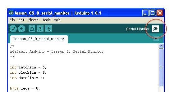
And the following window opens,
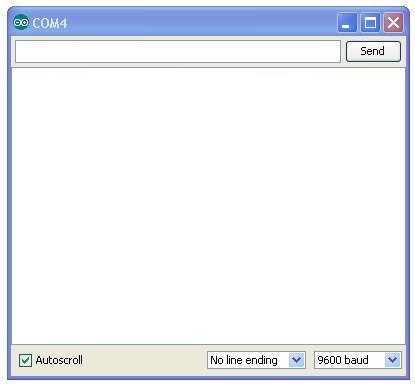
To test. Type 1 on the serial monitor and press send, and the led turno on!
Now, when I type 0, and and press send, the led turns off!
Also, when I press the button. I see the message in the screen!
My communication is working!!
This is a great exercise to start learning communications. Now, for networking, I will try to communicate using two boards.
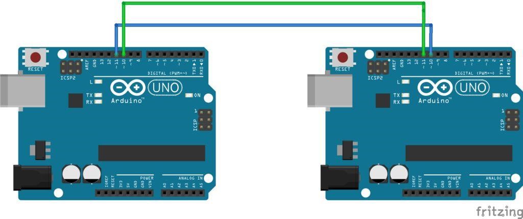
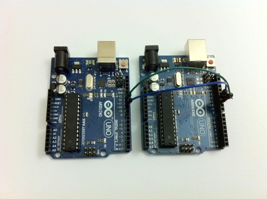
I will use two arduinos and connect the pin 10 of each Arduino to pin 11 of the other using the jumper wires, as shown on figure 1. Pin 10 is the RX pin and pin 11 is the TX. To communicate using serial protocol, you have to connect the TX to RX and RX to TX. Once that is done, connect it to your PC.
Hardware set up.
Now, I will open two session of Arduino IDE. Make sure they can access two different ports. It must be opened differently and you should not open the other session in the same window. Remember that when you connect your Arduino, windows will show you what COM port was assigned to each board. To verify, I can always open the device manager and check under the ports. To be able to communicate serially, we are using the SoftwareSerial library. To be able to use it, you just need to use the #include and then name the library you need. IN this case, we must add the following line:
#include <SoftwareSerial.h>
Then, we need to assign the pins used for the communication. This time we will use the SoftwareSerial chat(10,11) command. We will also create an integer variable named text.
SoftwareSerial chat(10, 11); // RX, TX
int text;
For the setup void, I will configure the baudrate and start the serial communication. Using the serial.println method to display a “Starting chat Program…” message. To avoid sending to much information at the same time, I will use a delay in order to make give it enough time. In this case, I added a 1 second delay using the delay() method. To test the communication, I use a chat.println() and send the “Hello World” message.
void setup()
{
Serial.begin(9600);
Serial.println("Starting Chat Program...");
chat.begin(9600);
delay(1000);
chat.println("Hello World");
}
Now, in the void loop() I’ll verify that the line is available. For this I use the chat.available() method. If this is true, then I check if there is an incoming message.
void loop()
{
if (chat.available())
Serial.write(chat.read());
If there is not message coming, then I check again if the communication line is available, and this time will send a message. Fot this, I first print a “Me:” For the text not to be displayed right next to the “:” a format tab is included using the \t. Then I use a while cycle with the line available as condition and capture the text to be sent in the variable text and use the chat.write() method to send it to the other Arduino, and the serial.write method to display it our screen.
if (Serial.available())
{
Serial.print("Me:\t");
while (Serial.available())
{
text = Serial.read();
chat.write(text);
Serial.write(text);
}
Finally, I just print a blank line so that the new message starts in a new line:
chat.println();
Serial.println();
}
}
Now, I uploaded the code to both arduinos and compile it. Once it's complete, I open the serial monitor on each IDE and start chatting with the other Arduino using the serial ide:
Arduinos chat communication.

It worked! This week helped me a lot to understand how communication and networking actually works. This is very important and before I had no Idea how do they work, so I actually learned a lot by doing these exercises.
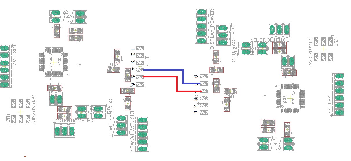
Now to test them with my board, I need will use the rx and tx pins in my board. If you focus on the pins 20 and 21, these are the pins for Tx and Rx in my microcontroller.
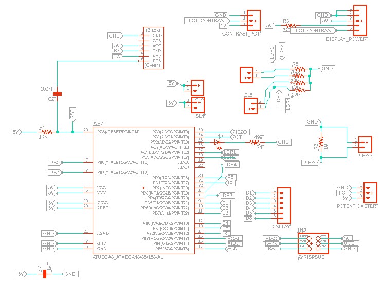
This ones are routed to the FTDI conector, especially the pins 4 and 5 as it can be seen below. This means, we can use them to communicate as in the previous example.
For this, we need to connect two of our boards.
After connecting them,I will adjust the code to be able to send a predefined message when a push button is pressed, and then show it on the LCD screen which can be connected to my port, because we can't use the serial monitor as in the example before, but we can see the communication using the screens.
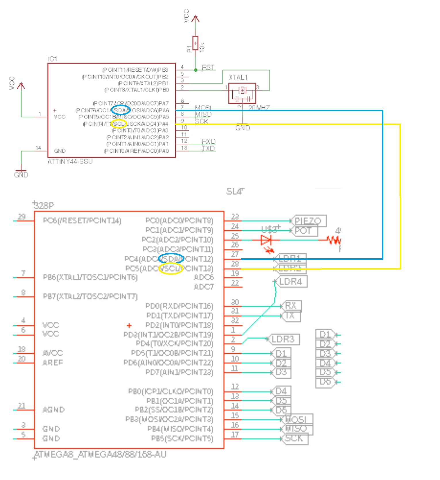
As this plan could have worked, when I read the requirements for this week, I saw that the communication between my boards should be addressed, not just wired communication via serial. This is why I decided to change the plan and try I2C communication, using the sda and scl pins in my final project board. I2c communication is a synchrnous type of communication where you have a message communicated between a master and a slave.
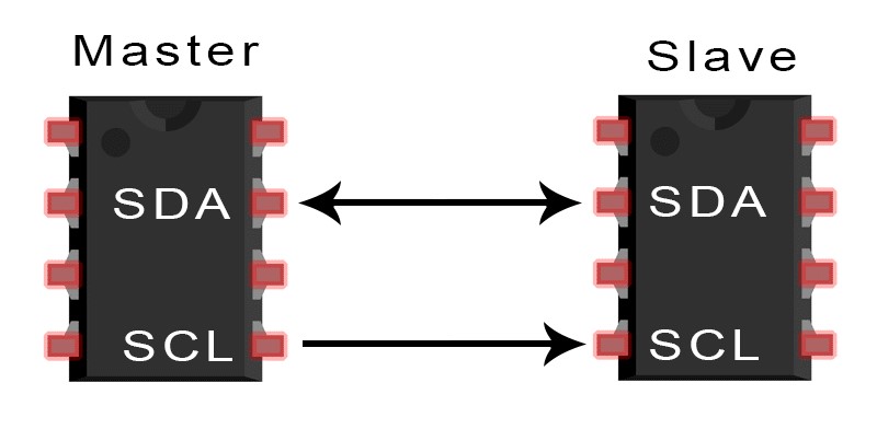
Usind 2 pins, SDA and SCL.
SDA (Serial Data) – The line for the communication to happen, where the master and slave, send and receive data.
SCL (Serial Clock) – The line that for the clock signal.
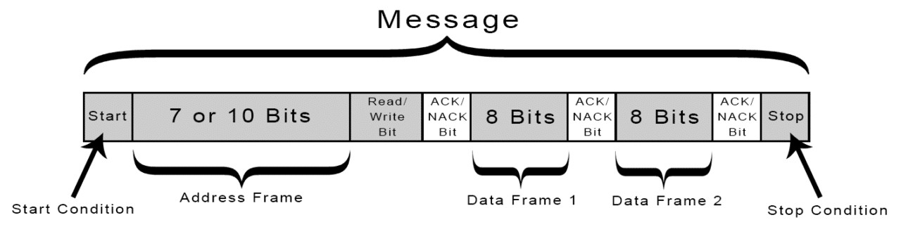
With I2C, data is transferred in messages. Messages are made up of frames or pieces of data. After starting, Each message piece for the address that contains the binary address of the slave, and then another piece for the information. The message also includes other pieces of information to make the communication happen, lick ACK and NACK bits.
As the boards to communicate shall be fabricated by myself, I will communicate to the helloboard I made for electronic design week. This means I would be communicating from an Atmega328 using an 8mhz internal clock, with a attiny84 using a 20mhz external crystal.
In the Atmega, I will use the wire.h library, which is by defualt included in arduino, but for the attiny, i need to use the TinyWire Library, which you can download from here: https://github.com/lucullusTheOnly/TinyWire
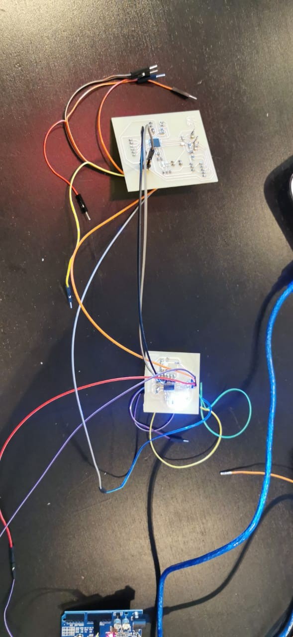
This is how I connected my boards.
The code for the Atmega will begin by including the wire library. Then I will use two codes fo send from the atmega to the tiny. I will use 50 as a correct address and 80 as a wrong address. In the void setup, I will define pin13 as an output, and then use the wire.begin method to start the communication and then to make sure the communication happens, I will set the clock to 10k to make it slower. Then in my void loop, I will begin the transmission, and send the message to address 50, and use the wire.write method to send it, and then the wire.end to stop the communication with a delay of 500 milliseconds. Then, I will again start the transmission but this time to a wrong address, and sending a wrong byte, and end the transmission.
Download File : MasterCode
For the ATtiny, i will start by defining a LED output in pin 3, and then create a variable to define the address of this slave device, and a variable to store the recieved data. Then in my void setup, I define the output pin, And turn it on. Then Using the TinyWire library command begin, I define its address (which will be the correct one),and the begin recieving data using the onRecieve command. Then In the void loop, I save the recieved data in the variable recieved, and if the value is the correct, I turn off the led, wait for 500 milliseconds, and turn it on again. However, if by any chance the value received is the wrong one, the led will stay on for 2 seconds.
This is the code
Download File : SlaveCode
COMMUNICATION VIDEO
As shown, the LED is all the time turning on and off in 500 milli second intervals, which means that only the correct byte is being send, and the wrong one is not recieved because its addressed to a different slave. This week I learned a lot about communication, and it was a big challange because I had to do all the boards my self, But I was very happy I managed to do it with the help of my teammates and my instructor.
Download File : comunications1 code
Download File : comunications2code