Interface and Application Programing
For this week, I will begin my interface and application programming week by testing Processing, a great source for creating graphics. The Processing IDE works for a computer like the Arduino IDE works for a micro-controller. The Processing IDE is similar to Arduino in terms of structure. It has setup functions, draw functions, and loop function just like an Arduino. The Processing IDE can communicate with the Arduino IDE through serial communication. This way, we can send data from the Arduino to the Processing IDE and also from the Processing IDE to the Arduino.
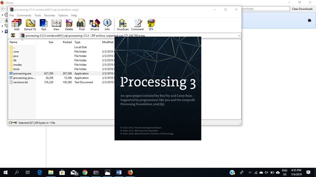
If you do not have already installed the Processing IDE, then you need to install it first. To install it, go to the link below and download the latest version of processing IDE.https://processing.org/download/
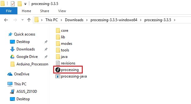
After downloading the latest version, open the Processing IDE Unzip that file and inside the unzipped folder you will find Processing application. And to run Processing, double click on that icon .
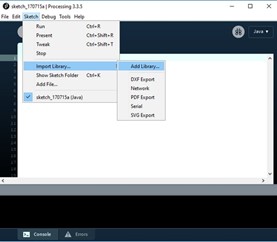
There are many libraries for different applications. You can also install some extra libraries manually or directly from the menu. To install new library from menu, go to: Sketch -> Import Library... -> Add Library.
After installing, open the Processing IDE and you will its interface
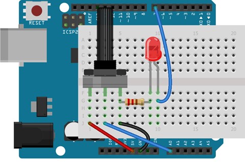
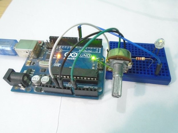
To begin testing, I will try a simple circuit, a 1k potentiometer connected to 5V and GND. The middle pin of the potentiometer to the A0 on Arduino. Then connect the positive pin of the LED to pin 7 on the Arduino and the negative pin of the LED to the GND pin through the 220 ohm resistor.
The Arduino IDE and the Processing IDE will communicate with each other through serial communication. The Processing IDE has a serial library which makes it easy to communicate with the Arduino.
When you move the potentiometer knob, the Arduino will send a value between 0 and 255 to the Processing IDE. The Processing IDE will then change the color of the serial window according to the movement of the potentiometer knob.
Similarly, when you press the mouse button in the serial window of the Processing IDE, the Processing IDE will send a ‘1’ or ‘0’ depending on the left or right mouse button to the Arduino IDE. The Arduino IDE will then turn the LED ON or OFF according to the button pressed.
The microprocessor code is very simple and can be found below
.
int led_pin = 7; // Initializing the LED pin
int pot_pin = A0; // Initializing the Potentiometer pin
int pot_output; // Declaring a variable for potentiometer output
void setup ( ) {
pinMode(led_pin, OUTPUT); // Declaring the LED pin as output pin
Serial.begin(9600); // Starting the serial communication at 9600 baud rate
}
void loop ( ) {
pot_output = analogRead (pot_pin); // Reading from the potentiometer
int mapped_output = map (pot_output, 0, 1023, 0, 255); // Mapping the output of potentiometer to 0-255 to be read by the Processing IDE
Serial.println (mapped_output); // Sending the output to Processing IDE
if (Serial.available ( ) > 0) { // Checking if the Processing IDE has send a value or not
char state = Serial.read ( ); // Reading the data received and saving in the state variable
if(state == '1') // If received data is '1', then turn on LED
{
digitalWrite (led_pin, HIGH);
}
if (state == '0') { // If received data is '0', then turn off led
digitalWrite (led_pin, LOW);
}
}
delay(50);
}
The Processing IDE will accept the data from the Arduino IDE through the Serial communication and will change the color of the serial window according to the data. It will also send ‘1’ or ‘0’ depending on the mouse button pressed. The Processing IDE has a serial library which makes it able to communicate with the Arduino IDE.
import processing.serial.*; // Importing the serial library to communicate with the Arduino
Serial myPort; // Initializing a vairable named 'myPort' for serial communication
float background_color ; // Variable for changing the background color
void setup ( ) {
size (500, 500); // Size of the serial window, you can increase or decrease as you want
myPort = new Serial (this, "COM3", 9600); // Set the com port and the baud rate according to the Arduino IDE
myPort.bufferUntil ( '\n' ); // Receiving the data from the Arduino IDE
}
void serialEvent (Serial myPort) {
background_color = float (myPort.readStringUntil ( '\n' ) ) ; // Changing the background color according to received data
}
void draw ( ) {
background ( 150, 50, background_color ); // Initial background color, when we will open the serial window
if ( mousePressed && ( mouseButton == LEFT ) ) { // if the left mouse button is pressed
myPort.write ( '1' ) ; // send a '1' to the Arduino IDE
}
if ( mousePressed && ( mouseButton == RIGHT ) ) { // if the right mouse button is pressed
myPort.write ( '0' ) ; // Send a '0' to the Arduino IDE
}
}
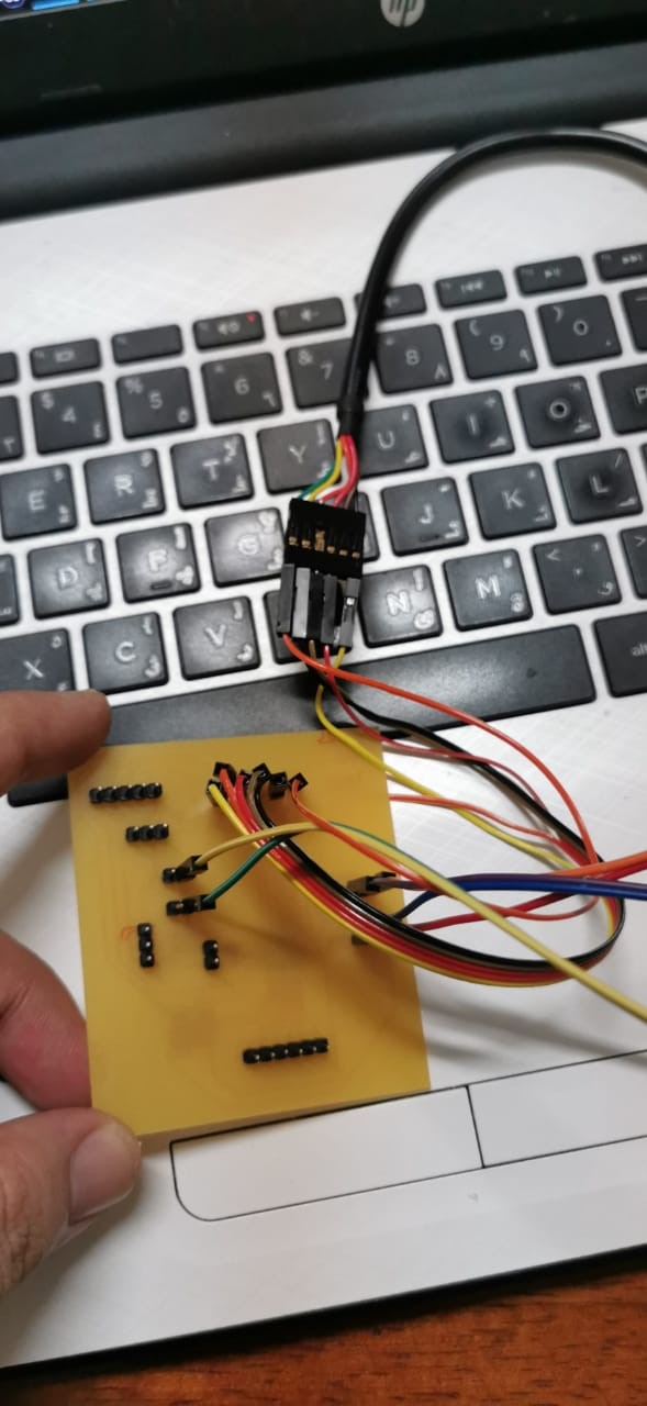
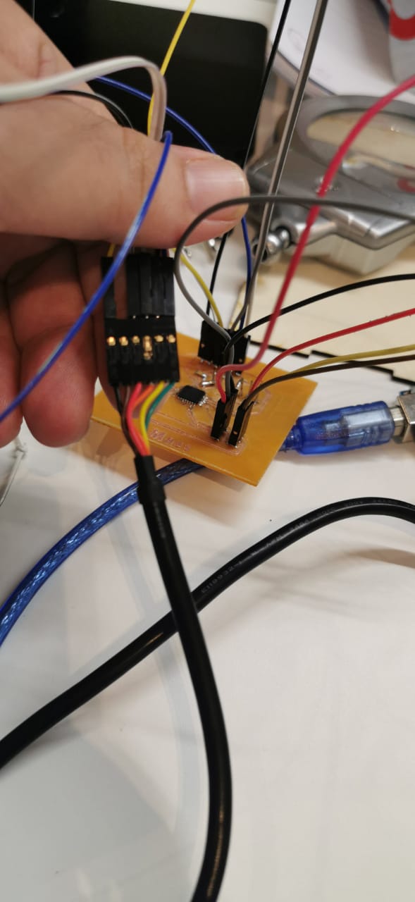
I'm planning to use my board that I designed to be used in the final projec. I used Eagle to Design my PCB board, using at atmega 328as a microprocessor.
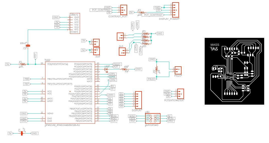
Download File for the PCB: PCB_Design
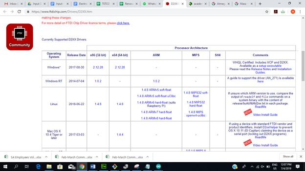
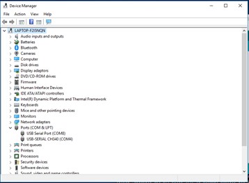
Now, Ill try a more complex interface and use my own board. For this, I first have to install the drivers of the FTDI cable to make sure the serial communication will work. I start by downloading the correct drivers
And after installing

I make a very simple program just to be able to test that the communication is working.
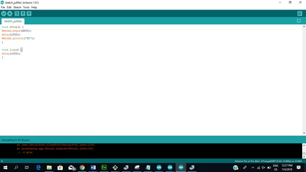
Basically, I just start the communication at a low baud rate, wait for 1 second, and then send hi. I upload this code to my board using this connection:
for this example, I will connect 3 leds to my outputs 3, 4 and a5. I will configure this pins as outputs, and when certain conditions are met (values recieved from the gui from the computer by serial communication) i will turn them on or off
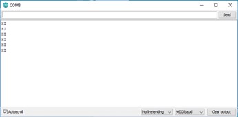
And when opening the serial monitor, I'm very happy to see that the information is being sent and received, so I can start working on my interface.
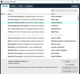
I will use a very usefull library called ControlP5 to create this project.
For this, I will open processing
Go to the library manager
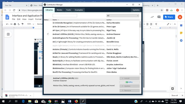
And search for controlP5 and install it
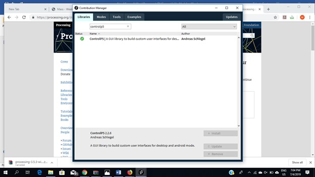
ControlP5 is a library written by Andreas Schlegel for the programming environment Processing. To add ControlP5 library to Processing just follow the add library process and search for ControlP5 and then click on install. Now you are ready to create your GUI application. For this, I will connect 3 leds to my board outputs, and will control them from my GUI.
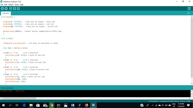
Next step is to write an Arduino sketch. Write a code in such a way that when Arduino receives a character through the serial port, it performs a particular task. An example code is shown below
if(val == 'r'){ //if r received
digitalWrite(11, HIGH); //turn on pin 11 (red led in our case)
}
So when Arduino receives character 'r', it sets pin 11 to High.
Now comes the Processing part.Using the Serial library in Processing we can use that to read and write to the serial port. So what I did was assign a function to each of the buttons to send some character to serial port, so when you press any button, it send particular char to the serial port. For example suppose we have a button called red, when you press button red it sends char 'r' to the serial port.
void red(){
port.write('r');
}
At the other end, Arduino receives that char 'r' and according to the received character it changes state of the pins.
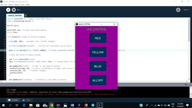
The Processing program is the following.
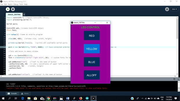
When running the code, the interface will look as shown. Now I can control Arduino using some GUI controls (for example Buttons).
Then I can change the values and the interface switch to fit my use .. i changed the last button to be All on and the colors will switch off the led .. now i can do anything by using processing .
video
Download File : Arduino code
Download File : Processing code