Input Devices
For this week, we are making our own arduino based board based on satcha kit. But until this is ready, we are going to read information from a sensor using arduino.
To start, lets learn the basics of Arduino inputs. I will try the following setup:
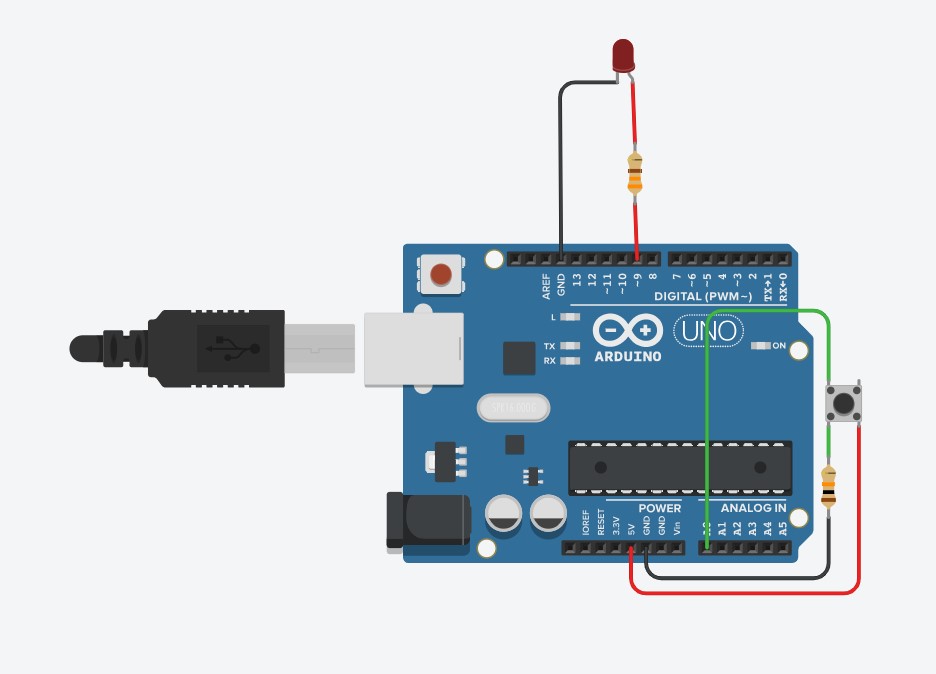
Arduino has two types of inputs. Analogue and Digital inputs. Digital inputs will only show us two options, on or off. While analogue inputs will receive values between 0 and 5 Volts and translate it into numbers using an ADC or analogue to digital converter and show numbers between 0 and 1023 proportionally. Normally, sensors will be using analogue inputs.
The button is normally open, which means that no conection between the button unless pressed. As connected, this means that the voltage on the analogue input 0 will be normally 0, but when the button is pressed, the 5 volts should go out the pin and the value received in the Arduino should be 1023.
Analogue outputs can be between 0 to 5 V and are controlled by values between 0 and 255. Because the input goes from 0 to 1023, and the output from 0 to 255, I use the map function to adjust the values to proportionally.
Based on the AnalogInOutSerial example, your first declare the two pin assignments (analog 0 for the button and digital 9 for the LED) and two variables, sensorValue and outputValue.
const int analogInPin = A0;
const int analogOutPin = 9;
int sensorValue = 0;
int outputValue = 0;
The only things that you do in the setup() function is to begin serial communication to be able to send the data to the serial monitor. I will be using this as an output to see the data on the screen.
void setup() {
Serial.begin(9600);
}
Finally, in the main loop, sensorValue is assigned to store the raw analog value read from the input. To adjust the range of the input to the one of the output, I use the map method. This method requires 5 arguments: the value to be mapped, the low range and high values of the input data, and the low and high values for that data to be remapped to. In this case, the sensor data is mapped down from its original range of 0 to 1023 to 0 to 255. Then, both the raw and scaled sensor values are sent to the Arduino Software (IDE) serial monitor window, and with a delay of 2 millisecond before starting the process again we have enough time to not saturate the communication port. Notice that for printing the data, I use the serial.print command for the first 3 data, so that the information is displayed in the same line, and only at the end I use the serial.println so that a new line is created for the next loop.
void loop() {
sensorValue = analogRead(analogInPin);
outputValue = map(sensorValue, 0, 1023, 0, 255);
analogWrite(analogOutPin, outputValue);
// print the results to the Serial Monitor:
Serial.print("sensor = ");
Serial.print(sensorValue);
Serial.print("\t output = ");
Serial.println(outputValue);
delay(2);
}
Upload the data into the Arduino and try it out.
Testing different Sensors.
Notice that there is a resistor between ground and the button. Most sensors are variable resistors that change their resistances accordingly to the variable they will measure. To be able to read this change, the easiest way to connect it is by using a voltage divider, which is used to convert the resistor change to a varying voltage, which is easily captured using the Arduino.
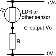
For your readings to be more reliable, you need to correctly select the value for R. The value of the resistor R determines the range (maximum and minimum values) of the output voltage Vo. For best results, you need Vo to have a large range and this is achieved if R is much larger than the sensor's minimum resistance but much smaller than its maximum resistance.
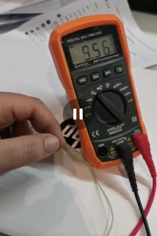
Use a multimeter to find the minimum and maximum values of the sensor's resistance, there is no need to be precise - approximate values will do. Then use the formula to choose a value for resistor R:
R = square root of (Rmin × Rmax)
Rmin = sensor's minimum resistance
Rmax = sensor's maximum resistance
Choose a standard value for R which is close to the calculated value.
For example if your LDR has Rmin = 100![]() and Rmax = 1M
and Rmax = 1M![]() : R = square root of (100 × 1M) = 10k
: R = square root of (100 × 1M) = 10k![]() .
.
To test, this, lets change the button for a potentiometer as shown below:
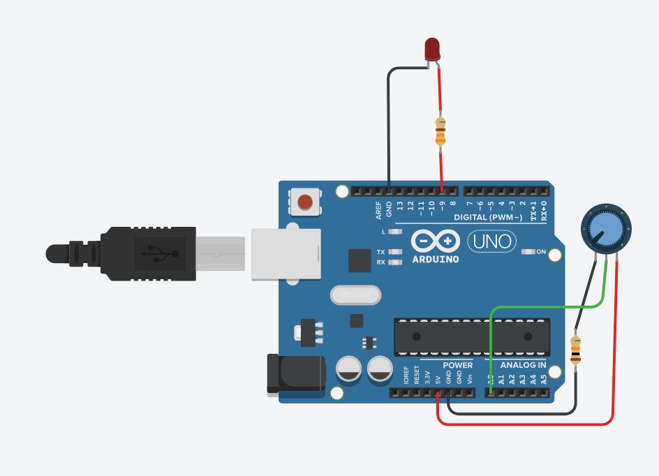
Use a potentiometer to correctly select the value of R, and test the input and output values using the serial monitor. If done correctly, your input values range should go from 0 to 1023 or very closely.
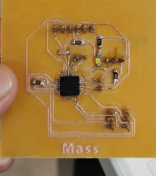
Now, i will use my own board to test my circuits
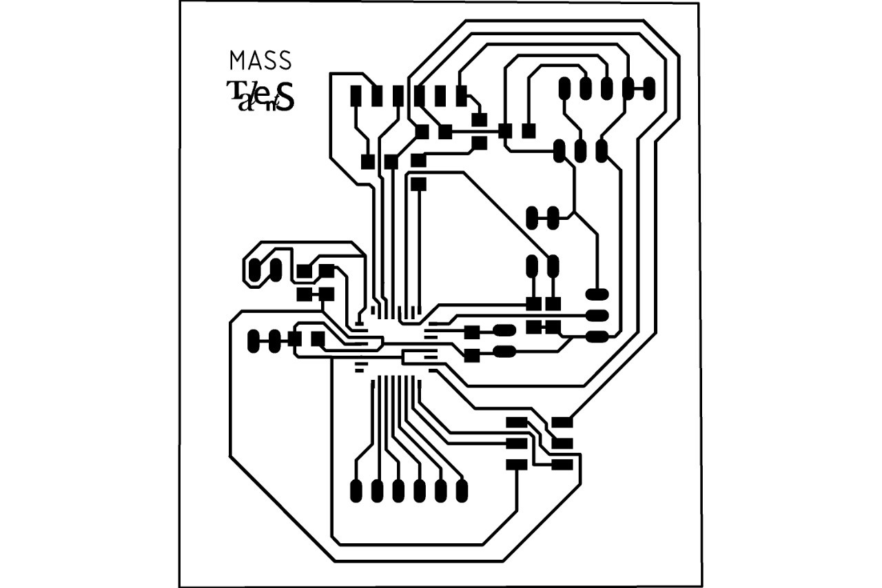
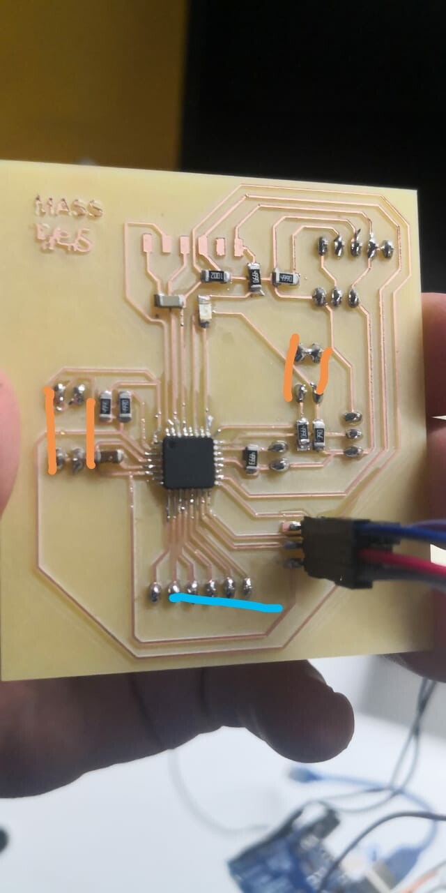
After routing and soldering by board, I have a programable micro controller that will work as an arduino.
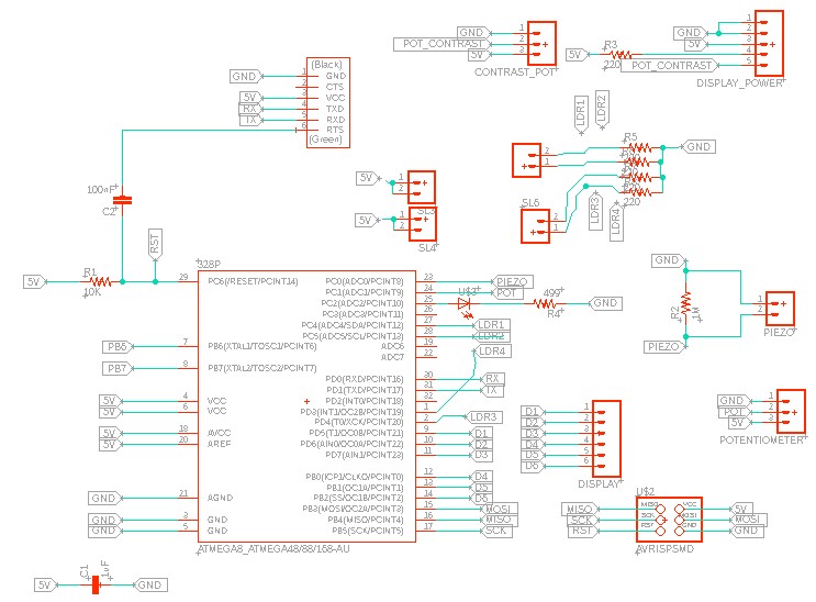
As shown in the schematics, pin holders sl3 and sl4 are conected to vcc, and the Sl5 and sl6 have a resistor to ground. This means that the sensor we put in between will be already connected with the voltage divider needed, and will be connected to my pins 27, 28, and 1 and 2.
This means I can connect directly my LDRs to between this pin holders as shown below.
Now, I can write a program that just reads the values of these 4 pins, and depending on the desired output, I can just program it to show a different code, as I will show in the output week.
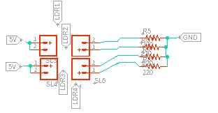
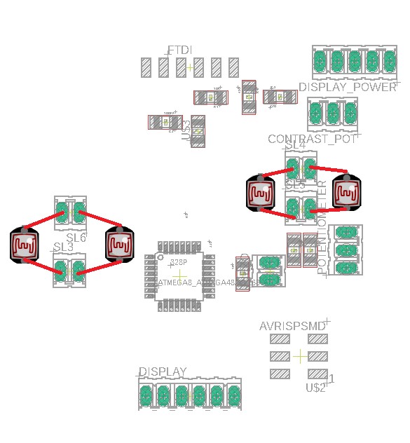
To test it in my board, I first connected with jumpers to a protoboard as shown below
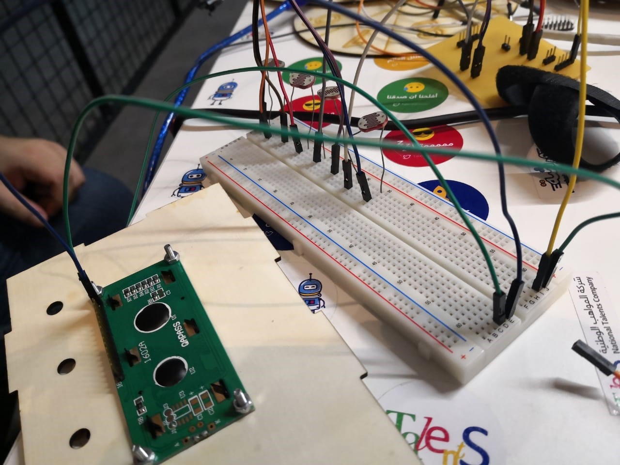
I connected the LDRs between the orange lines shown in this image
And when reading the data sheet, two of the LDRs are going to a digital input, and two of them are going to a analogue input. For the first two, I just need to compare if the value is HIGH, it means the laser is pointed to the LDR, otherwise it would be low, and for the analogue, I need to compare to a treshold.
In my code, in the setup, i declare the 4 pins as input
pinMode(3, INPUT);
pinMode(4, INPUT);
pinMode(A5, INPUT);
pinMode(A4, INPUT);
And then, in the void loop, I start by reading the 4 values,
int ldr1 = analogRead(A5);
int ldr2 = analogRead(A4);
int ldr3 = digitalRead(3);
int ldr4 = digitalRead(4);
2 of the using analogue read, and 2 of them using digital read. For the two analogue inputs, I just compare if the values is lower than a threshold,that in this case, because of the value of my LDRs and resistors used, is 200. This value will vary from 0 to 1024 depending on how much light is pointed to the LDR, and when testing with the laser, 200 was a suitable value. For the digital pins, I just compare if the digital input is HIGH, this would mean that the laser is pointing the LDR, otherwise, it will be Low. In case none of the LDRs are pointed at, it will display a message saying Can you solve me. In the output week I will explain how the LCD display works, in this week I will focus only on input.
if (ldr1 > 200) {
lcd.setCursor(0, 1);
lcd.print("Red Code: 1234 ");
} else {
if (ldr2 > 200) {
lcd.setCursor(0, 1);
lcd.print("Blue Code: 1234 ");
} else {
if (ldr3==HIGH) {
lcd.setCursor(0, 1);
lcd.print("Green Code: 1234 ");
} else {
if (ldr4==HIGH) {
lcd.setCursor(0, 1);
lcd.print("Yellow Code:1234 ");
} else {
lcd.setCursor(0, 1);
lcd.print("Can you solve me?");
}
Here you can find the complete code.
Download File: the LDR code
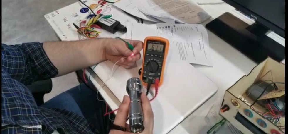
To characterize my input device's analog levels and digital signals,I will see how the resistance of my LDR changes when I point the laser to it, and when I cover it.
According to the data sheet,
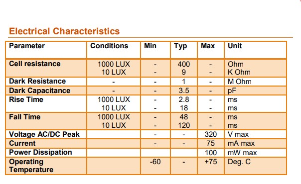
The resistance should vary from 400 ohms to 9 K ohms depending on the light conditions, but as the LDR is exposed to more light, the resistance should decrease.
As seen in the picture on the left, when pointed with the laser, the LDR resistance comes down to almost 600 ohms, but when covered, as shown in the right, the resistance goes up to more than 9Kohms.
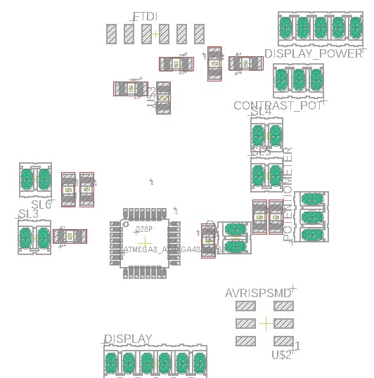
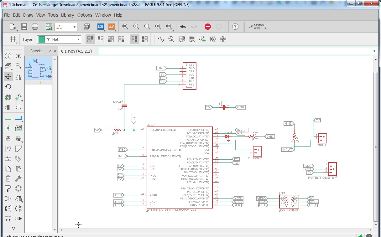
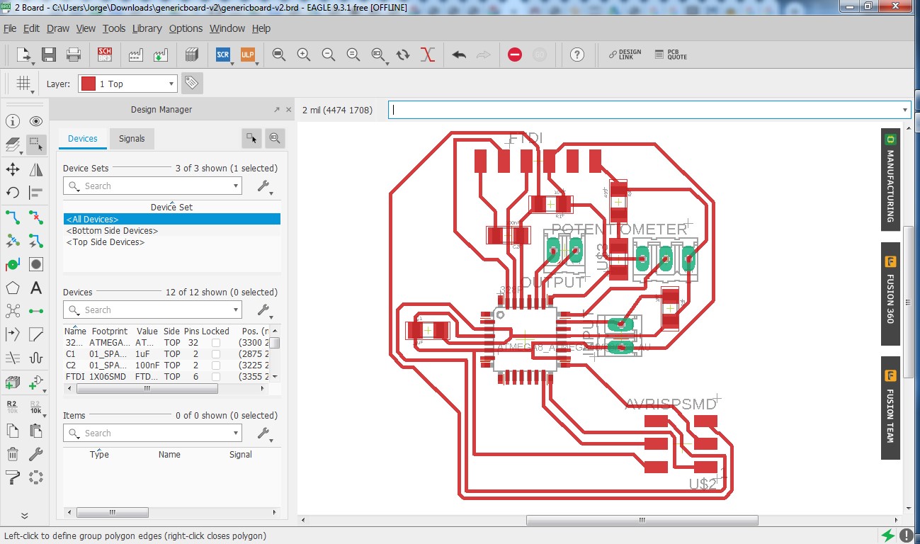
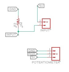
As our global evaluator said it was not possible to use the same board for input, output, and final project, I created a new board for input and output. As in input, i will use a potentiometer. The schematic and board view of the board designed is the following:
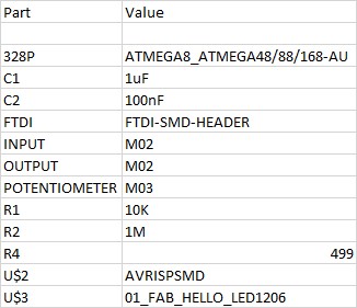
The part list for this board is the following:
For this week, I will focus mainly in this part of the board, where you can see Ihave the 5v and ground for the potentiometer, and the middle pin will go to atmega pin for input. Additionally, I left a generic pin to place a sensor in a voltage divider, where one pin is conected to 5v, and the other one is connected to ground through a resistor, and before the resistor I take a signal to take it to the atmega.
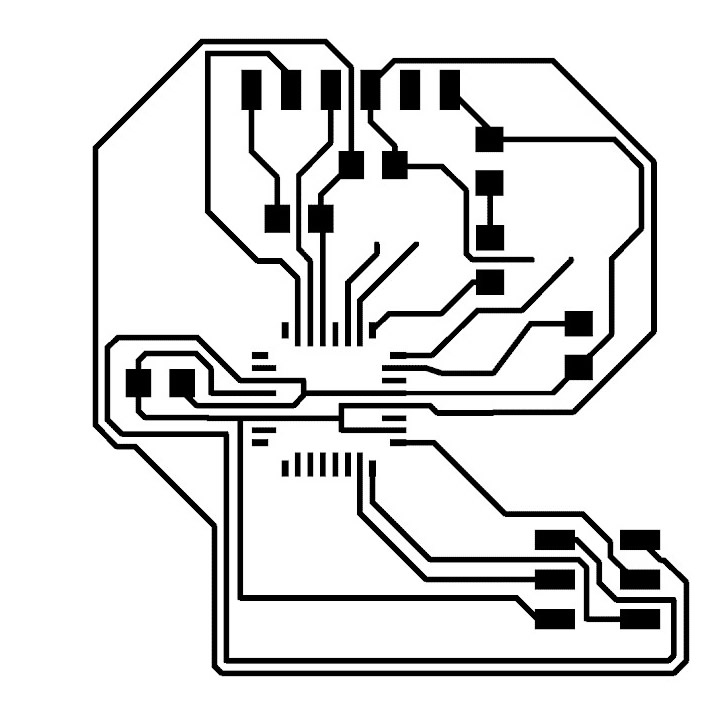
This is the routes I will mill in the carvey:
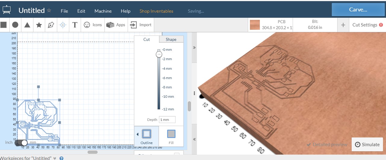
Here we can see the milling interface:
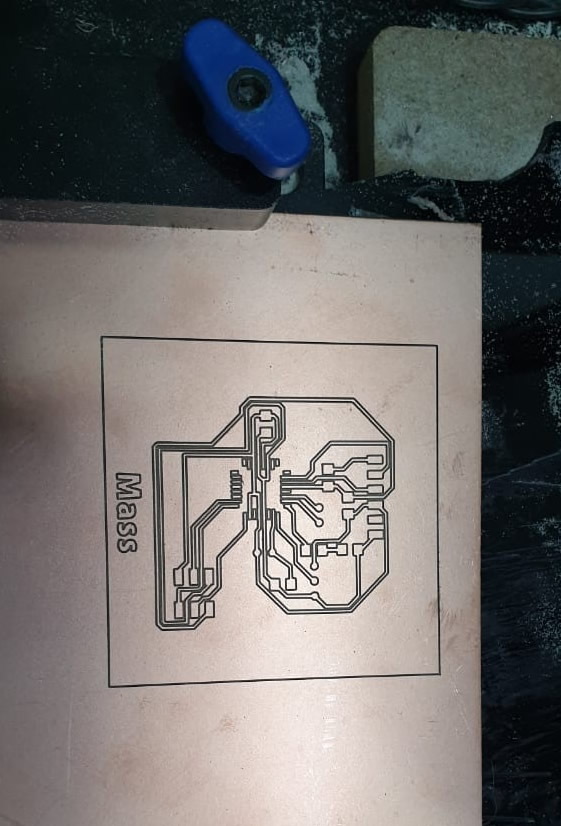
And here the result of the milling
And here my board after soldering
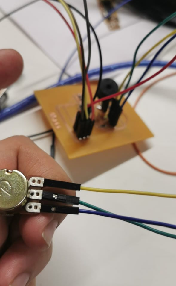
Now, I will do a simple code that uses 1 potentiometer as input, and one buzzer as output. Once the potentiometer crosses the treshold value, the buzzer will sound.
Here you can see my board with the elements connected
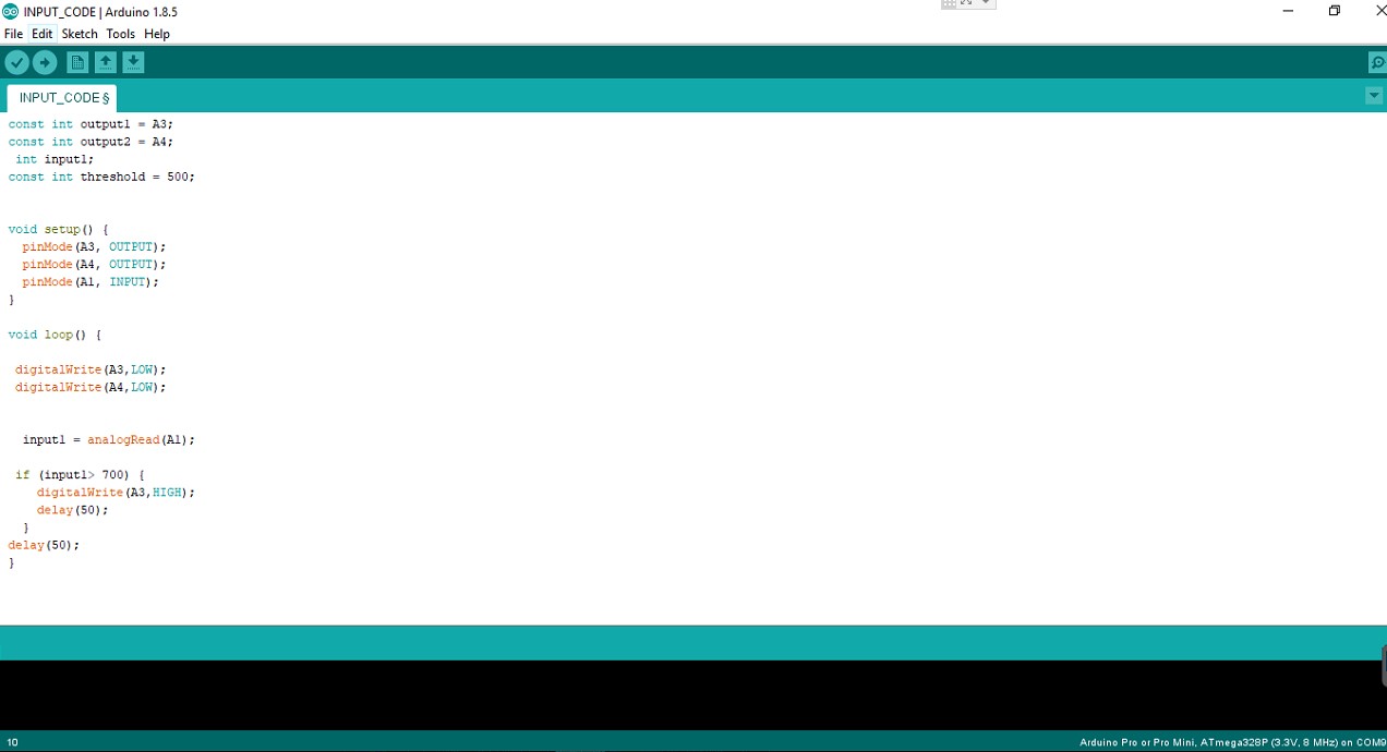
Here you can see the code, and here you can download it. INPUT_CODE.ino
Download File: INPUT_CODE
And here you can see a video of it working:
Download File: INPUT_CODE
Download File: the eagle bored Design
Download File: Input&output board.brd
Download File: ioboard.sch
Download File: ioboard.svg