Embeded Programming
The arduino IDE uses a “human readable”code, which will make sense to you (sometimes), and will be organized for a human to follow. The software then translates this code into machine-readable code to be executed by the Arduino. In this week, I will try to understand and explain the machine readable code, and then try to write the code in C, in machine readable language. The first thing I will try is to understand the blink code of the arduino program.
// the setup function runs once when you press reset or power the board
void setup() {
// initialize digital pin LED_BUILTIN as an output.
pinMode(LED_BUILTIN, OUTPUT);
}
// the loop function runs over and over again forever
void loop() {
digitalWrite(LED_BUILTIN, HIGH); // turn the LED on (HIGH is the voltage level)
delay(1000); // wait for a second
digitalWrite(LED_BUILTIN, LOW); // turn the LED off by making the voltage LOW
delay(1000); // wait for a second
}
This code is very simple, you start by defing the parameters in the void setup, where we are saying that the built in led will be used as an output, and then, in the void loop, which is going to be repeating for ever, you turn the output to high, what for 1k miliseconds, or 1 second, and then turn it to low, and wait for another second. This code is very simple and easy to follow.
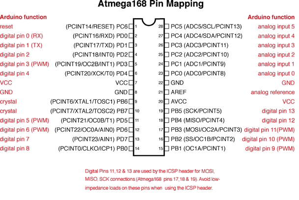
Now, I will try to translate the simple blink code in arduino into c. For this, I first need to understand the datasheet and see how is the microcontroller actually connected. To have a better understanding of the arduino board, I will look at its schematic and read the datasheet of the atmega 328
Download File: Atmega doc
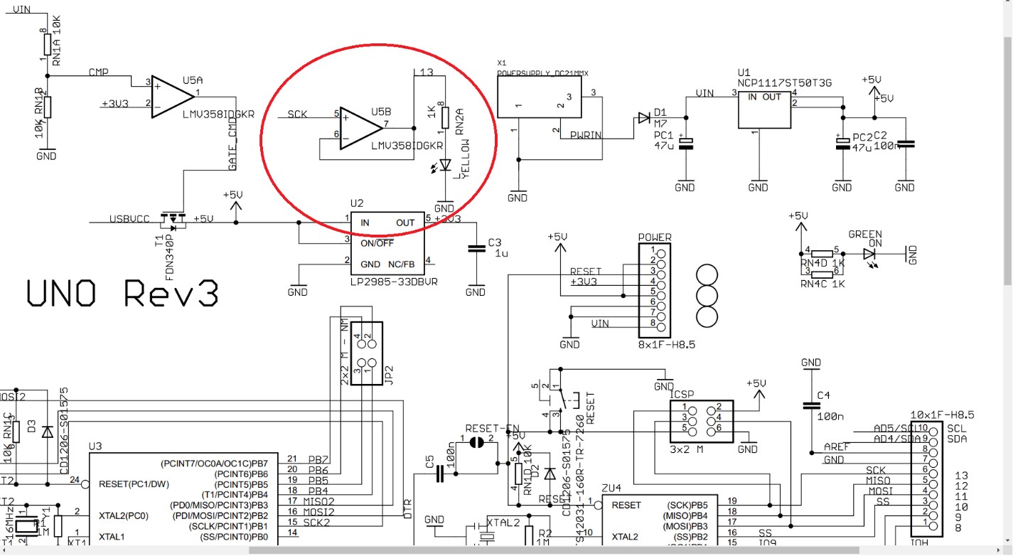
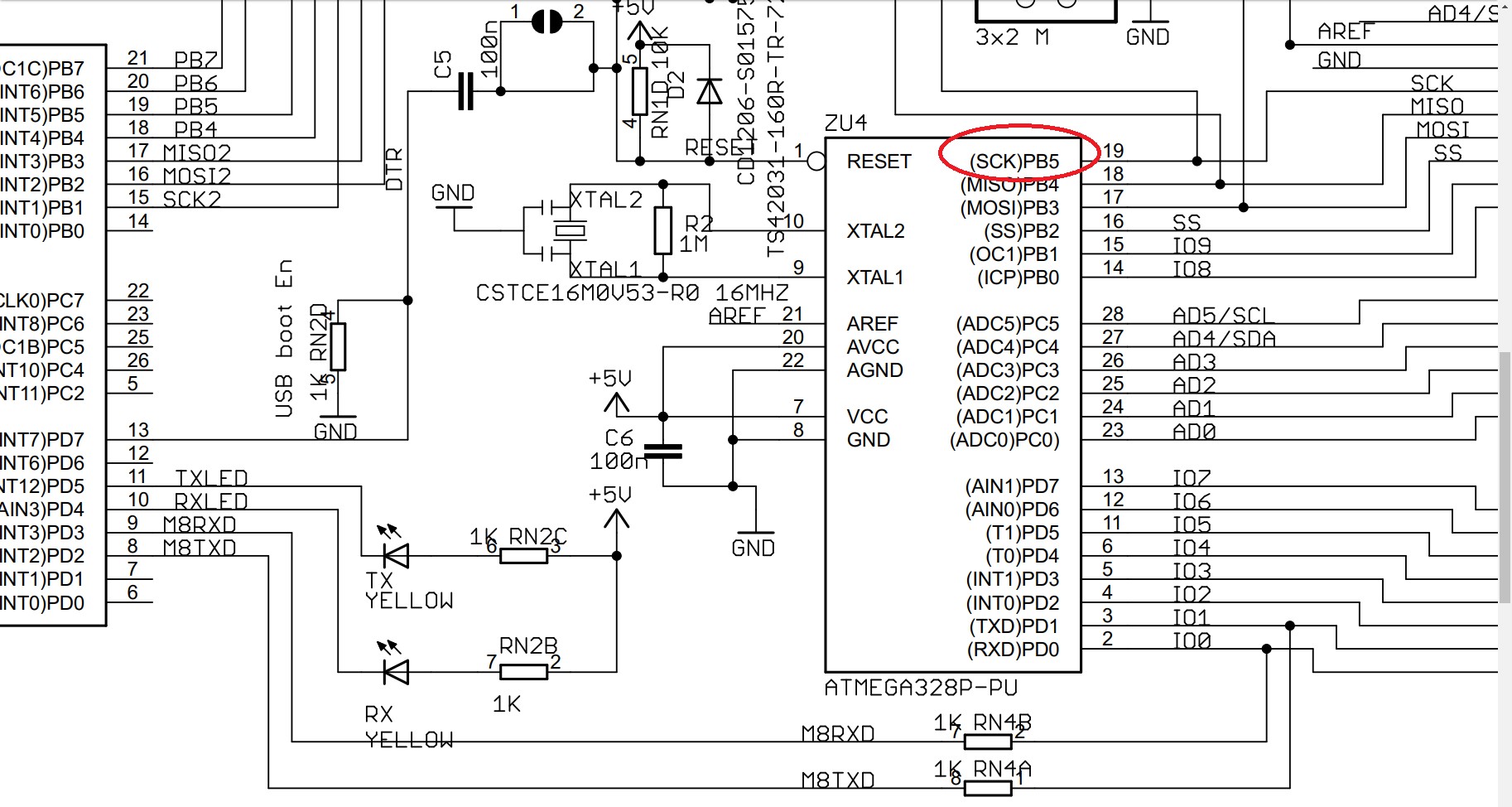
Checking the schematic, you can see that there is led connected on board, and that this one is actually coming from the SCK signal from the Atmega, which internally is pin PB5 as shown below.
With this information, I know exactly what pin I need to address using C. To be able to program the arduino using C, we need a compiler. In this case, I’m using Code Blocks.
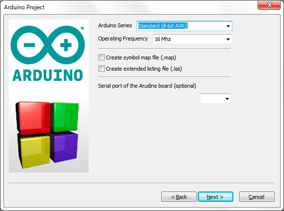
After downloading and installing it, you can select a new project, and you have two options, AVR or Arduino. You should select AVR and not Arduino, because we want to program in C. Click Next and give the project a name, if you wish you can change the location of the file, and click Next. It will ask for the compiler, and we will use the option by default. Click Next and now I will select the chip in my arduino, that as we saw before in the data sheet was the Atmega328p. Click finish and we are ready to work. A blank screen will open. On the left side. Expand, work space, double click on sources, and select main.c.
Now we are ready to write a code in C. We need to include two files for the code to work. First, the avr/io.h, which has the input and output pins, and the util/delay.h, for being able to create a delay.
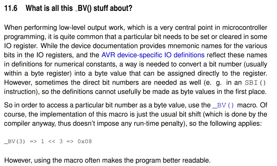
To change the values in C, we need to use the Bit Value Macro, which is called using the _BV command.
#include <avr/io.h> // header file file for input output pins
#include <util/delay.h> // header file for delay.
int main (void)
{
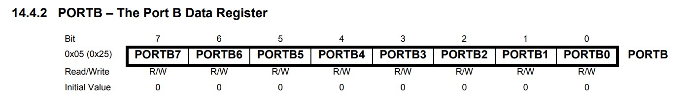
The first thing we need to do is declare the pin as output. For this, we need to change the value of the DDRB, or Port B Data Direction Register. By using the Bit Value Macro, we are assigning pin B5 as output.
<> /* set pin 5 of PORTB for output*/
DDRB |= _BV(DDB5);
Now, we need to turn the led on. For this we are changing the value of PORTB. For this, we are using the bitwise “|=” and “&=” assignment operators
while(1) {
/* set pin 5 high to turn led on */
PORTB |= _BV(PORTB5);
_delay_ms(1000); //delay 1 second
/* set pin 5 low to turn led off */
PORTB &= ~_BV(PORTB5);
_delay_ms(1000); //delay 1 second.
}
}
Now, the program is ready, but we need to upload it to the arduino. Click on the gear like icon located below the menu bar to compile and build the files, and then go to tools in menu bar and click on Arduino Builder. A new program will open.
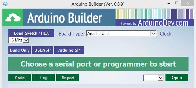
Click on Load sketch / hex file and locate the hex file from the location you saved the project. Don’t change Clock. Connect the arduino and select the COM port assigned, and as soon you click on COM port, the Arduino Builder will start to program it, after a few seconds, the Programming is done, and the LED will start to Blink.
EXTRA CREDIT. Trying to use python!!
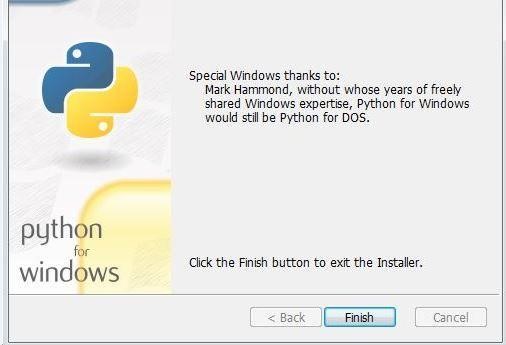
To program the arduino using Python, we need to install the Python IDE and PySerial, in order to control the Arduino.
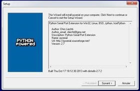
Then, install pyserial, which will is an API that will allow us to communicate using serial communication with Arduino.
Now, with both installed, you can control your Arduino using python. The script for Python would be the following:
import time #Required to use delay functions
Import serial #Serial imported for Serial communication
ArduinoUnoSerial = serial.Serial('com8',9600) #Create Serial port object called ArduinoUnoSerialData time.sleep(2) #wait for 2 secounds for the communication to get established
print ArduinoUnoSerial.readline() #read the serial data and print it as line
print ("You have new message from Arduino")
while 1:
var = raw_input() #get input from user
if (var == '1'):
ArduinoUnoSerial.write('1')
print ("LED turned ON")
time.sleep(1)
if (var == '0'): #if the value is 0
ArduinoUnoSerial.write('0')
print ("LED turned OFF")
time.sleep(1)
Make sure to update the code with the right Communication Port in order to be able to communicate. Now, on Arduino, we should program this code.
int data;
int LED=13;
void setup() {
Serial.begin(9600); //initialize serial COM at 9600 baudrate
pinMode(LED, OUTPUT); //declare the LED pin (13) as output
digitalWrite (LED, LOW); //Turn OFF the Led in the beginning
Serial.println("Hello!,How are you Python ?");
}
void loop() {
while (Serial.available()) //whatever the data that is coming in serially and assigning the value to the variable “data”
{
data = Serial.read();
}
if (data == '1')
digitalWrite (LED, HIGH); //Turn On the Led
else if (data == '0')
digitalWrite (LED, LOW); //Turn OFF the Led
}
Notice that you are not physically programing the Arduino with python; you are just stablishing the communication, running the script in python and then transmitting it to the Arduino via serial. The microcontroller itself would be all the time waiting for input through the serial communication.
I also made another example using scratch for arduino, which is a software design by MIT for kids to learn programming by using blocks. Please watch the video to see how it works.
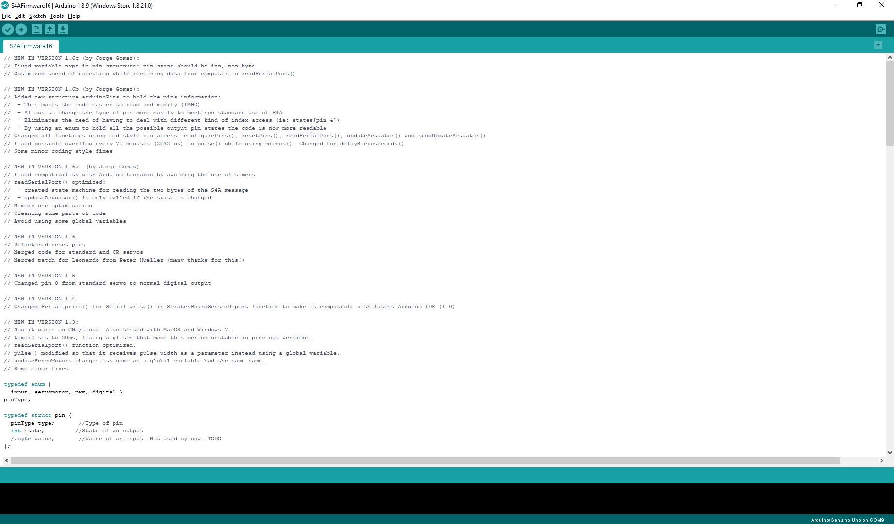
For this, I download the firmware of Scratch for arduino to my board.
After this, I download and install the scratch for arduino interface to my computer,
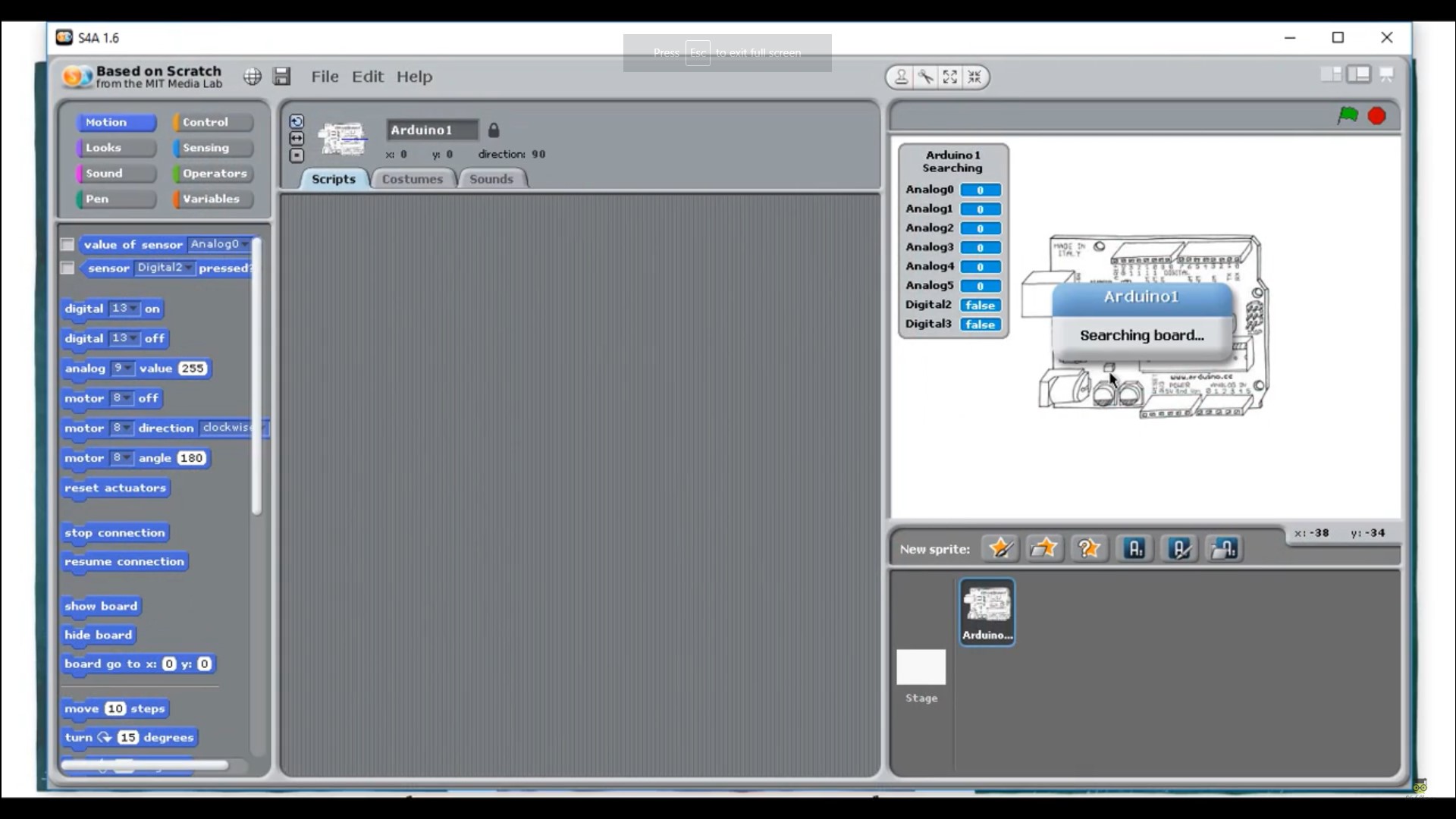
and after installing, I can see the interface. It will begin searching for the arduino with the installed software.
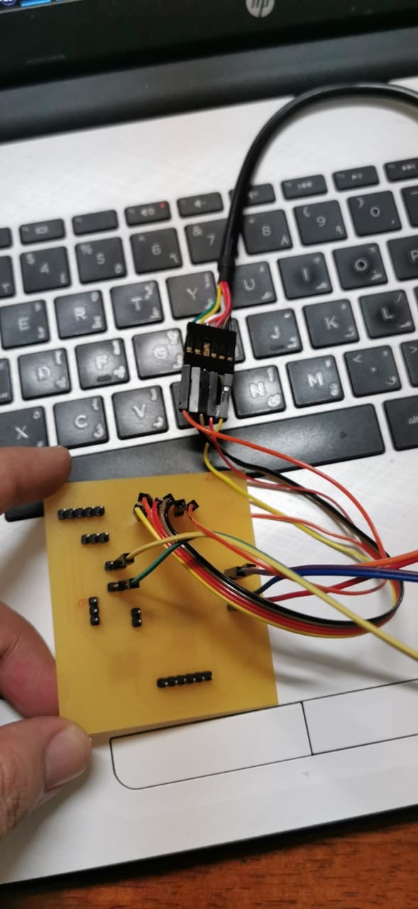
For this, I connect my board with the FTDI connection for serial communication.
And now, the scratch for arduino interface shows that it detects the arduino.
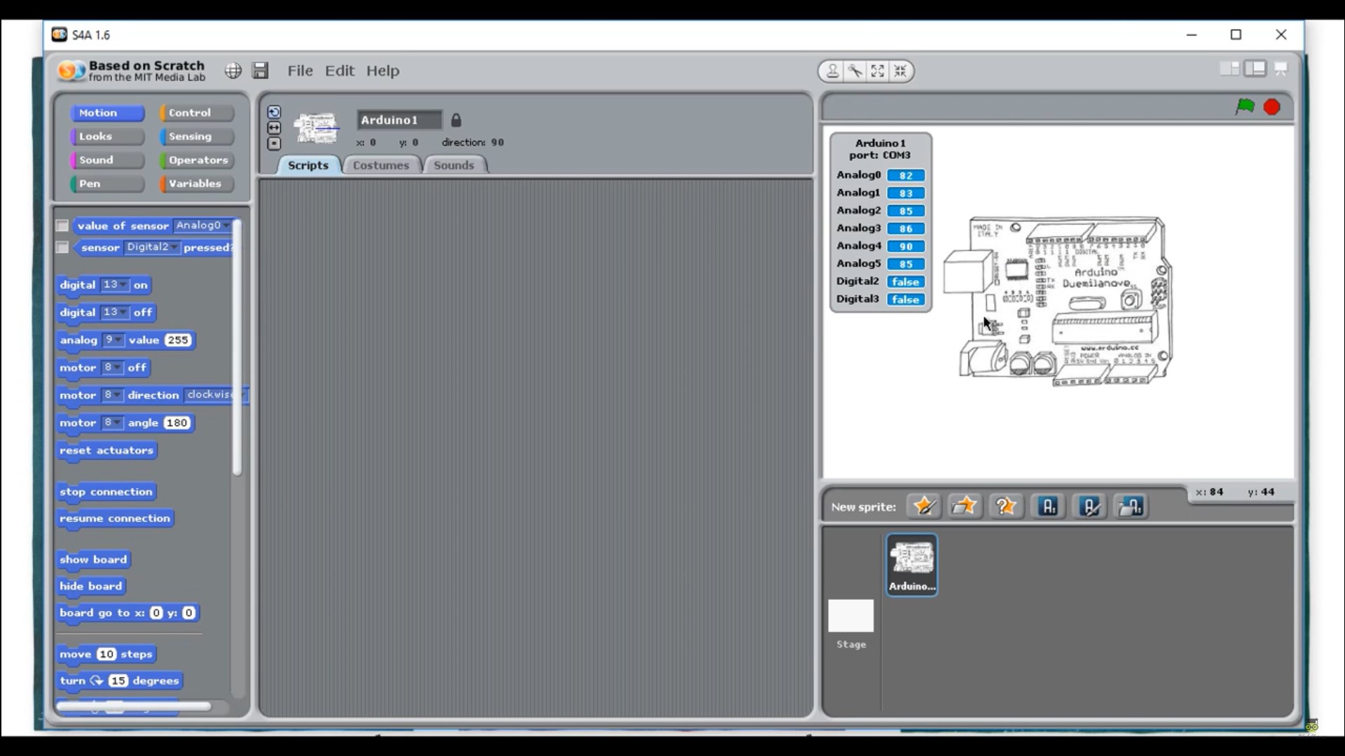
And I can begin programming with blocks. In the video I show the process of how to create it, but the final result is shown below, which I also simulated in thinkercad to see if it worked.
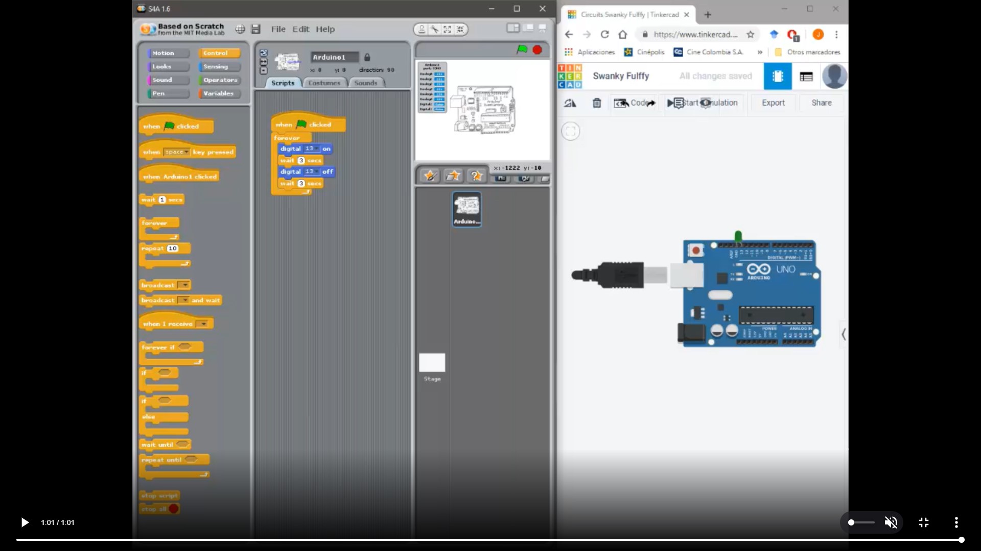
And here you can see it working in the arduino.
The VIDEO OF BLINK EXAMPLE (with 3 second delay) WORKING IN MY BOARD
After this week, I understood much better the difference of the lenguages, and don’t understand why C is so complex if the human readable code of the arduino IDE is so much simpler and easier to understand. Im very happy technology evolved and made programming so much easier.
After fabricating my own board, which i show below:
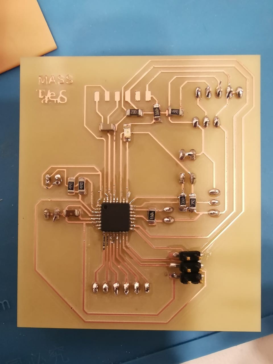
I program it and using an arduino as programmer, and after connecting all the sensors and lcd screen, I tested the result.
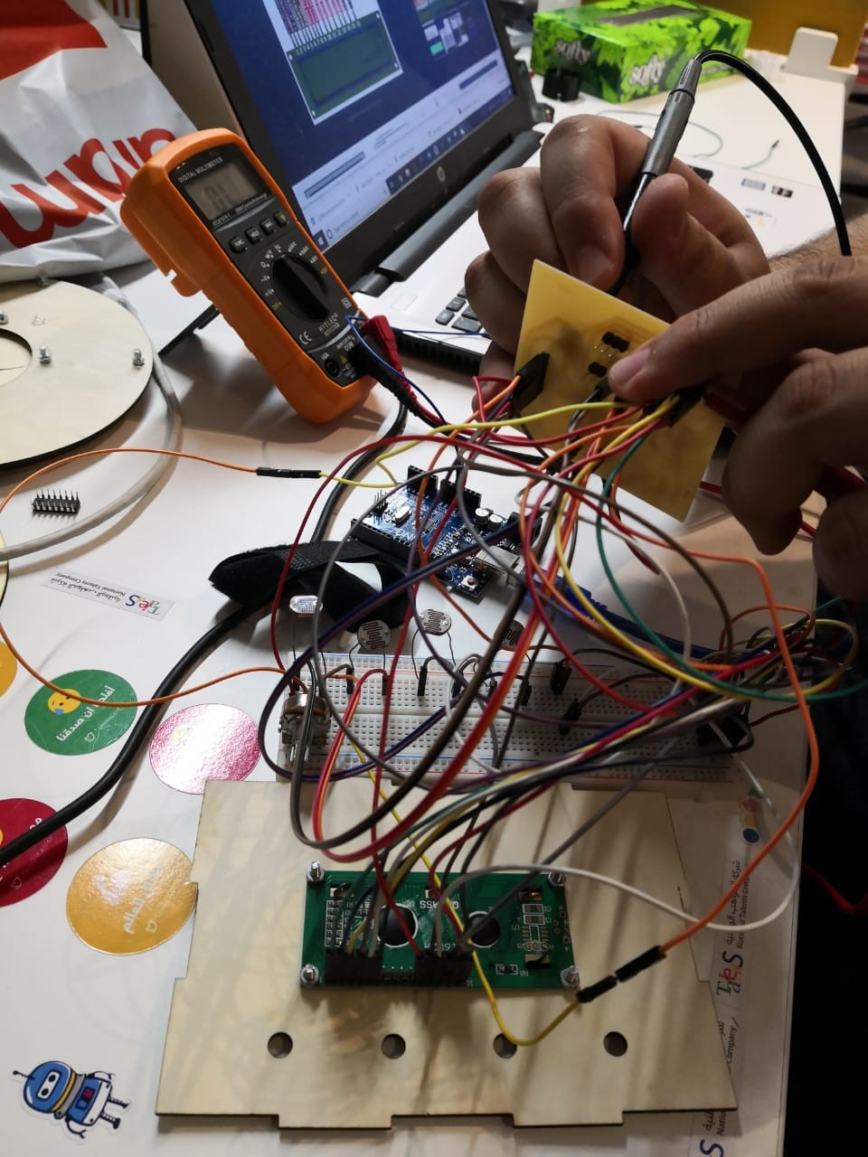
You can see in my final project page a more detailed explanation about the code and how I made it, but here, you can see that its working:
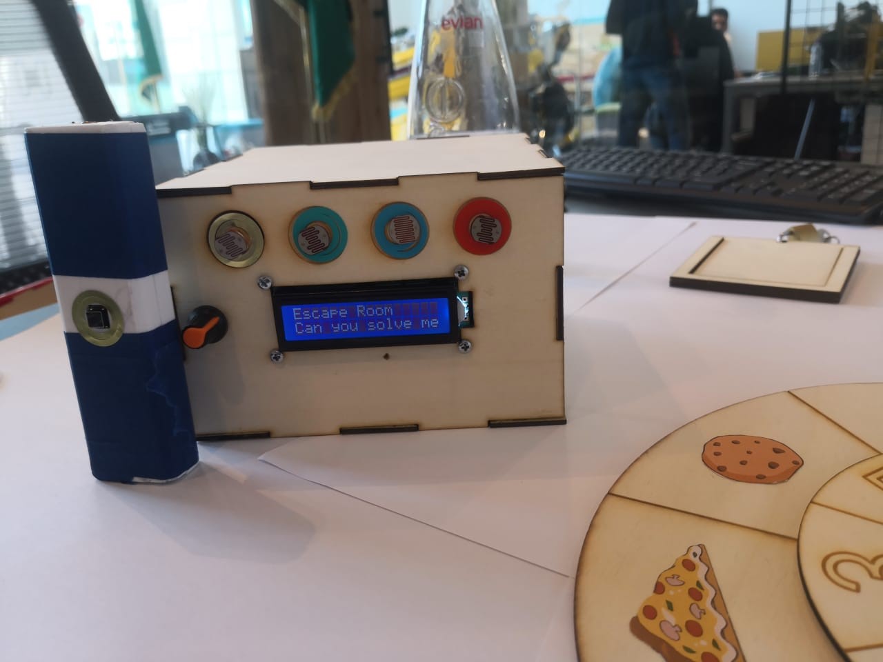
LDR Boxing Test
Also you can check my final project Page:
http://fabacademy.org/2019/labs/dhahran/students/mohammed-alsenwar/final_project.html
Download File: Arduino uno
Download File: Atmega doc
Download File: Atmega map
Download File: S4a code