Output Devices
Let's learn How do we can read and program the output device
What is the Output devices and in what we can use it
The Output devices is any piece of computer hardware equipment which converts information into human-readable form. In brief, output unit is responsible for providing the output in user readable form. It can be text, graphics, tactile, audio, and video.. for more information Click Here!
In this week assignment, I’m going to test some output devices that I’m planning to use in the final project. The first thing is 7 segments display one digit, because there are some types that have more than one digit (one digit means that I can represent one number only at once, so from 0 to 9) They call it 7 segments because of the component has 7 LEDs as segments to form the digit. Reference
Seven Segments
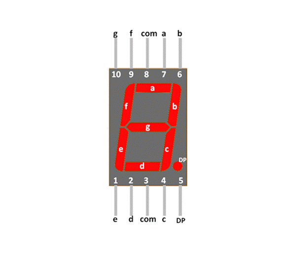
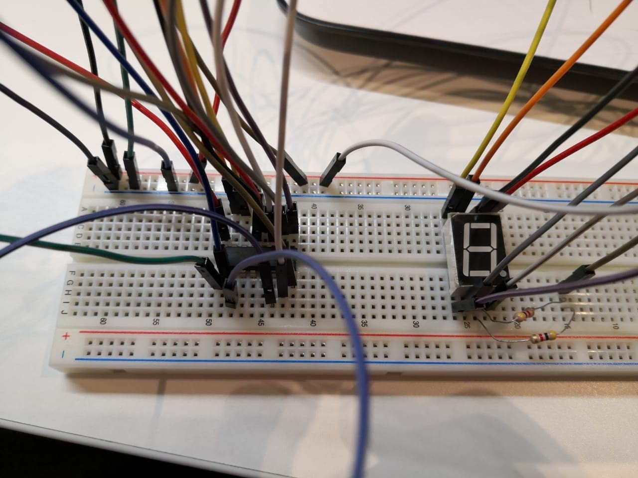
In general there are two kinds of seven segments, one is called common Anode and the other on is called common Cathode. As shown in the above figure, there are 2 pins called com, if the 7 segment is common Anode that means the com pin should be 5 volts and any segment I want to turn on the pin should be GND. In this case the one segment gets closed circuit and the segment will light up. The one that I have here is common Cathode, so I’m going to connect the com pin to GND and any segment pin should be 5 volts to turn the segment on. I tested that also by connecting one segment to make sure this is the right component before doing the whole connections.
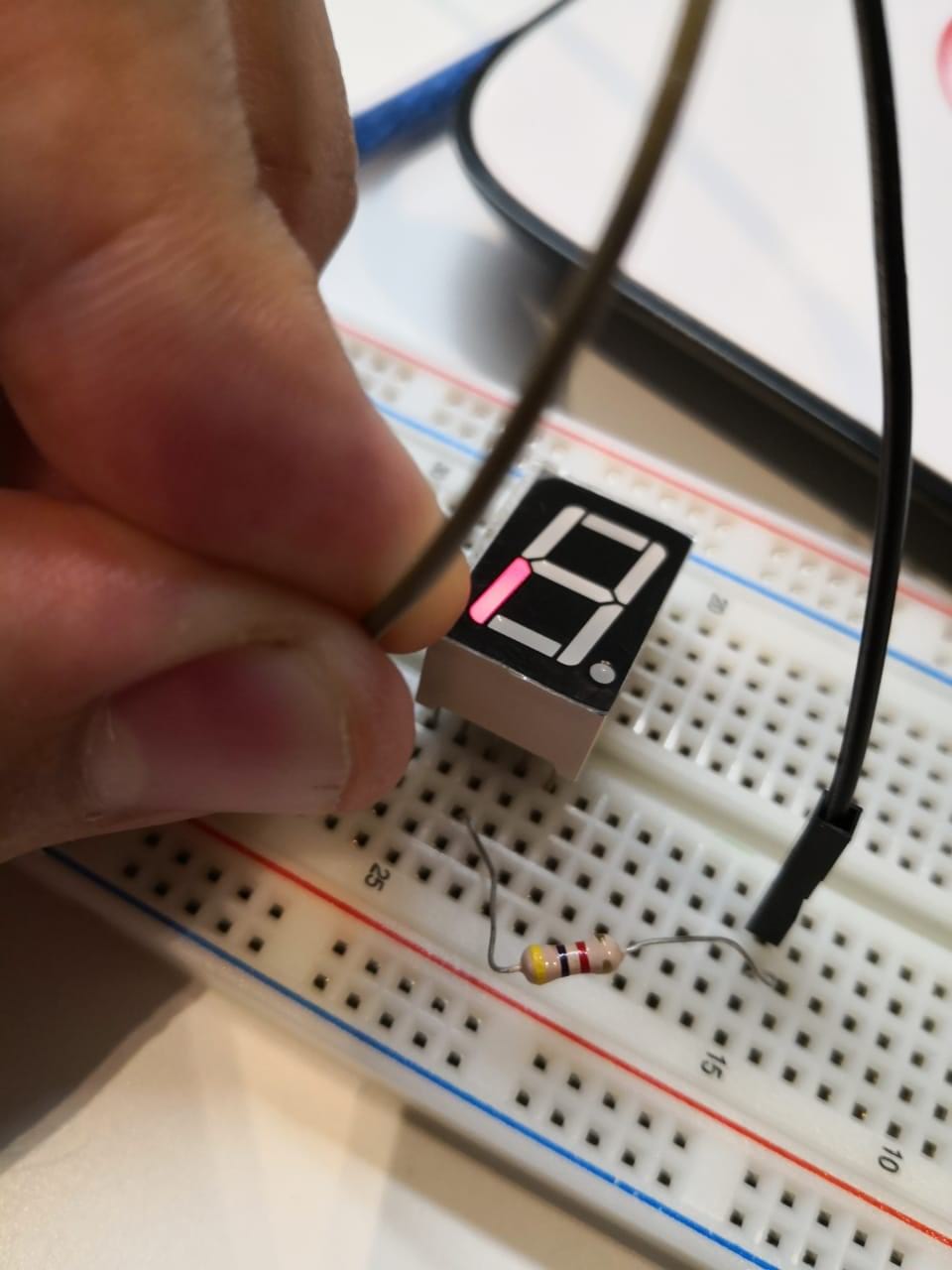

I used one resistor to limit the current and keep the seven segment safe. Als, there is something to note that the component has a dot and you can light it up as well

As a simple conclusion, the component has 8 LEDs and the cathode is common for all of them, so we can make the component itself easily as the following figure
Now, I can connect the seven segment directly to any microcontroller board, but it needs at least 9 pins! Which is too much and the code will not be easy as I’m controlling every single segment to form the number that I need to represent. So, one of the solutions is to get an IC (integrated circuit) called BCD to seven segment decoder. BCD means (binary coded decimal) it’s 4 pins give us for different signals, these signals represent the number in decimal but it’s coded to be as binary 4 bits and the IC converts the 4 signals (4 bits) into segment to form the number. Here are the binary and what means in decimal :
BCD (binary code) 4 bits |
Decimal |
0000 |
0 |
0001 |
1 |
0010 |
2 |
0011 |
3 |
0100 |
4 |
0101 |
5 |
0110 |
6 |
0111 |
7 |
1000 |
8 |
1001 |
9 |
In this case, I can get what I need (numbers from 0 to 9) as the 7 segments one digit. The 4 bits are basically 4 microcontroller pins that go to IC (BCD to 7 segment decoder) and the IC is connected to 7 segment directly to convert the 4 bits that come from microcontroller to the segments to show the numbers from 0 to 9 for example or as I program the function that I need to do with it.
The IC number that I just got is 7447 BCD to 7 segment decoder.The data sheet
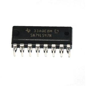
The data sheet is very simple and easy to understand and use. The IC has 16 pins, 4 of them will be as an input from my board ( pin number 1,2,6,7) and 7 pins will be as an output to connect to 7 segment (pin number 9,10,11,12,13,14,15) each one represents one segment.
As I’m going to use my board Attiny44, I prepared the code at first, to program the board before using the same pins to be connected to IC.
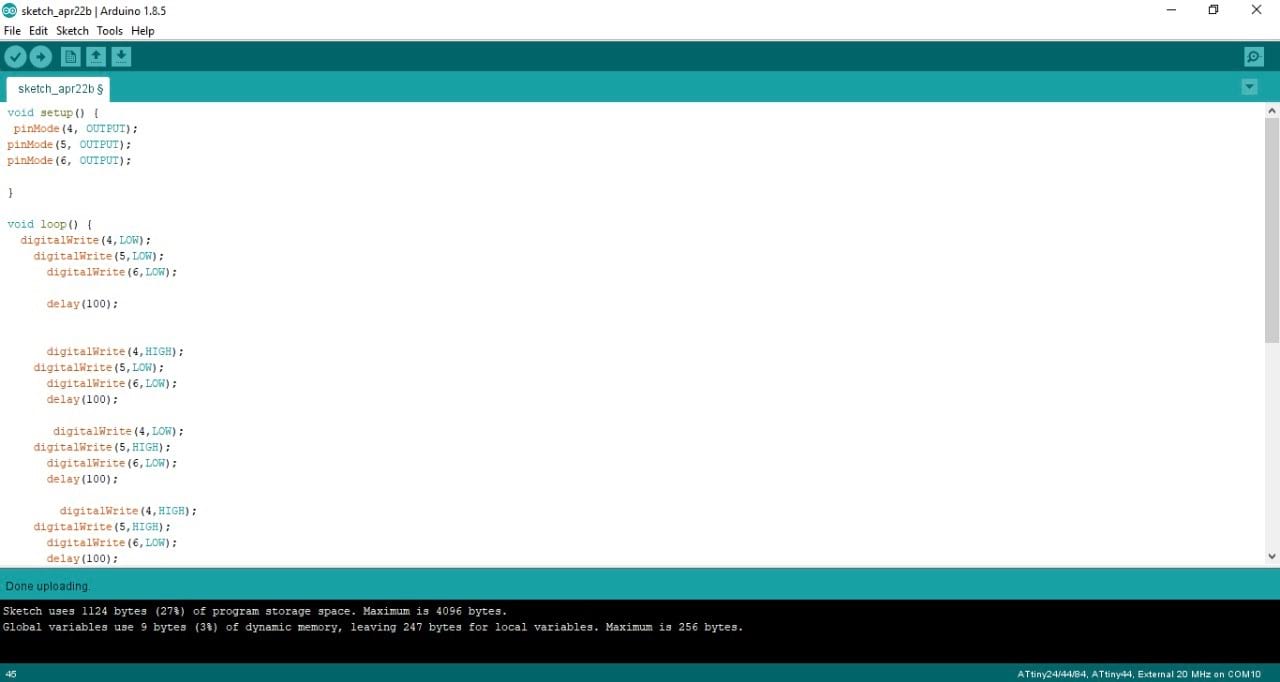

I did a simple code to count from 0 to 7 as I considered 3 pins only from my board Attiny44. I can't do more than number 7 using only 3 pins. The code is representing a counter from 0 to 7. The pins I decided to use from Attiny44 are ADC4, ADC5, ADC6. I mentioned them in the void setup as outputs using pinMode as I’m going to connect them to IC to represent the the numbers in binary from 0 to 7 as decimal.
In the void loop, I did change the pins status eight times to make the binary code that makes the number from 0 to 7 and delay between them. The same as the table that I did above, but note that 0 in logic means 0 volts means LOW in the programing. 1 in logic means 5 volts means HIGH in programing.
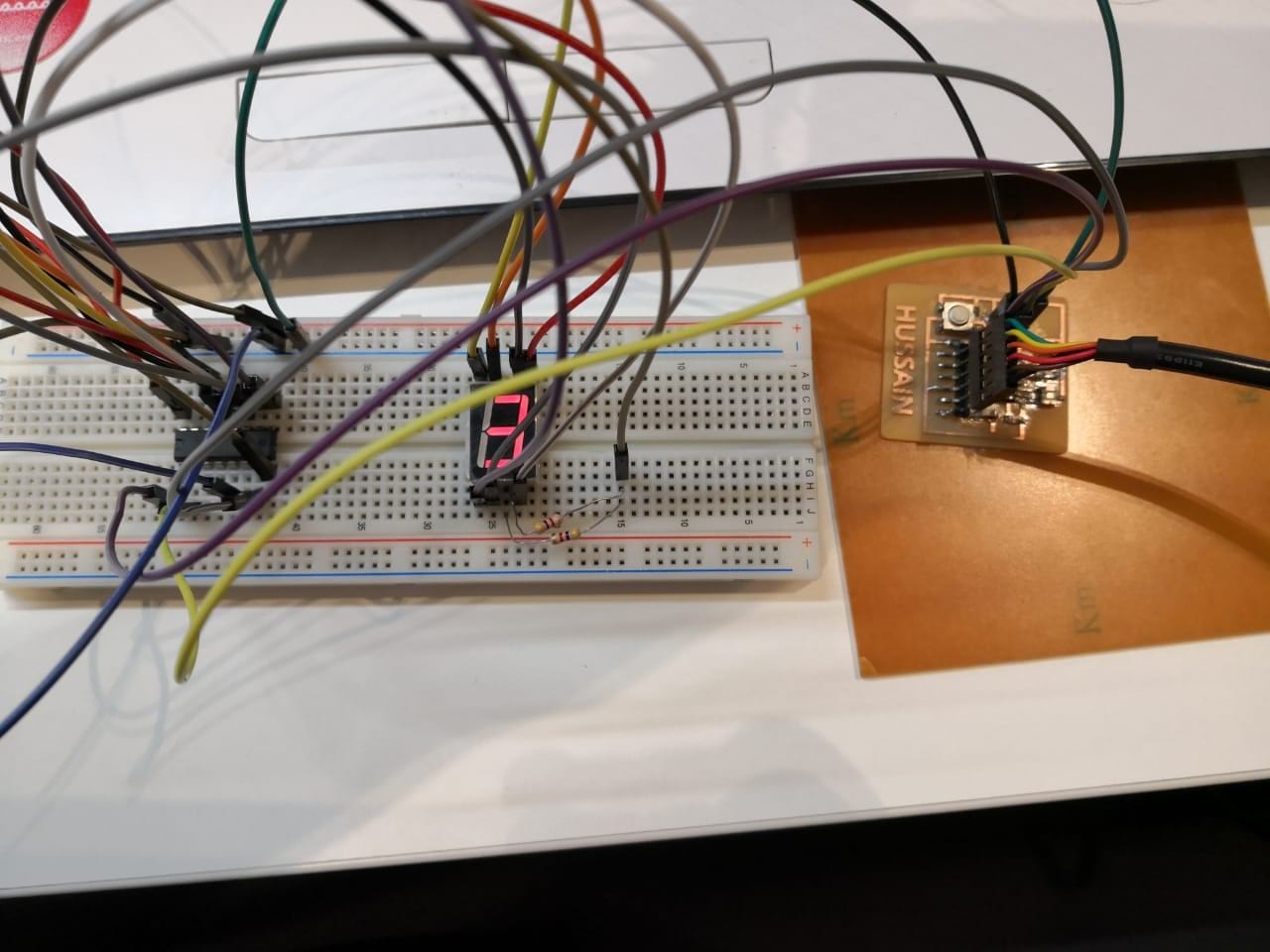
I uploaded the code by connecting the arduino and used it as ISP, using the same method that I did in week 9 assignment (Embedded programming). And then disconnected the Arduino, because the Attiny44 keeps the program. And now it’s the time to connect the circuit with IC and 7 segment.
First, I connected the Attiny44 pins to the IC, I need 3 pins only plus 5v and GND. the connection as the following:
Attiny44 pins |
IC 7447 pins numbers |
VCC |
16 |
GND |
8 |
ADC4 (pin number 9) |
7 |
ADC5 (pin number 8) |
1 |
ADC6 (pin number 7) |
2 |
On the other side, the connection between IC 7447 and the 7 segment
IC 7447 pins numbers |
7 segment pins |
9 |
e |
10 |
d |
11 |
c |
12 |
b |
13 |
a |
14 |
g |
15 |
f |
8 |
com |
Note: I used a resistor connected to the com pit to make sure the current is limited.
Now, the connection is complete and the circuit is ready. I powered the circuit up by connecting the FTDI cable>
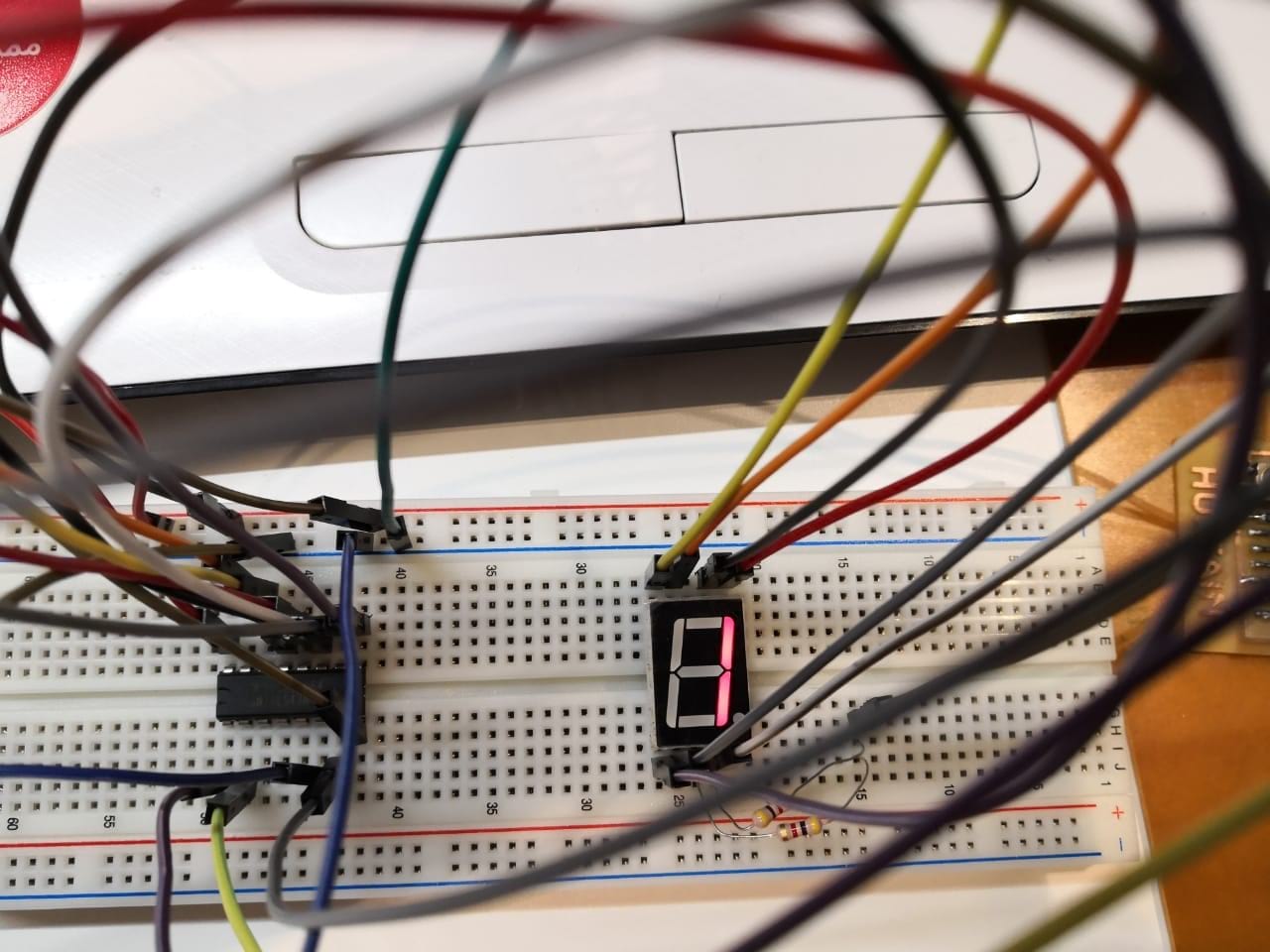
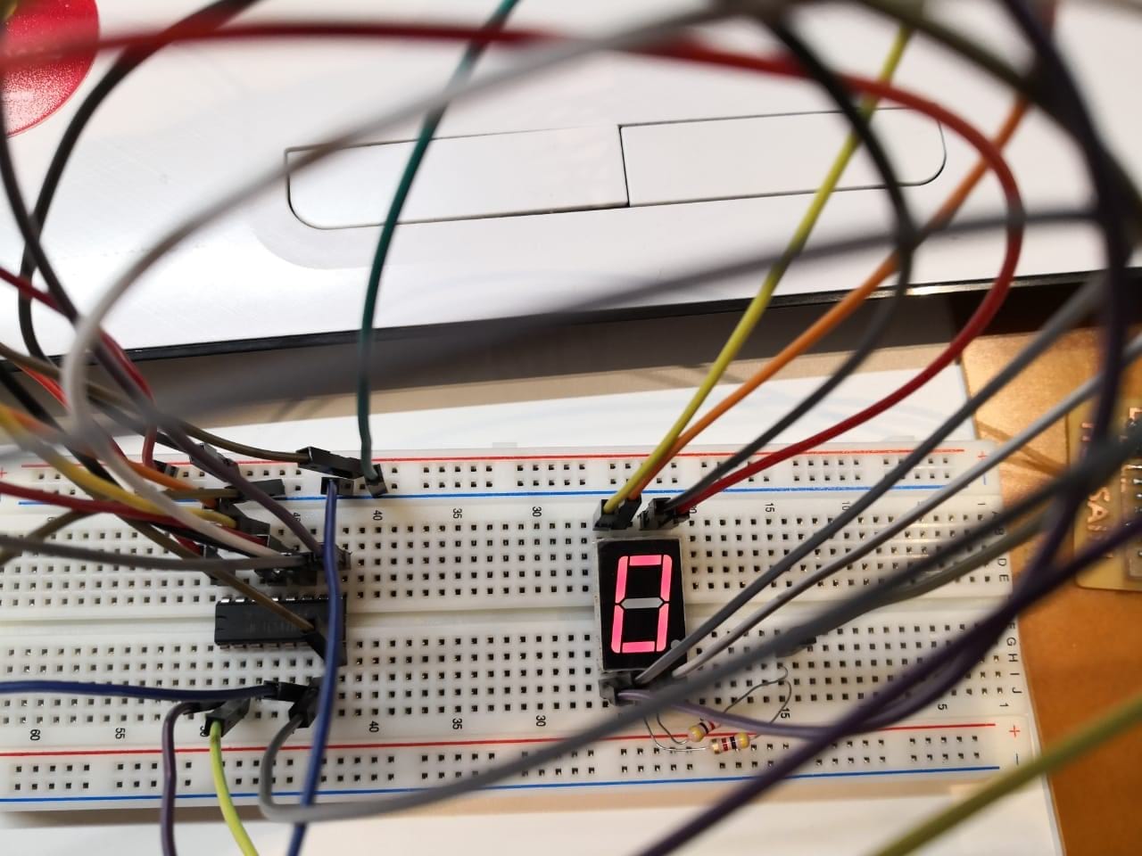
>As shown above the counter started counting from 0 to 7
Fourth test, and the diagram:
I can make the counter from 0 to 9 by connecting the forth bit using reset pin as output. Also, I can add another 7 segment and connect them to each other to make the counter from 0 - 99. As I mentioned above some 7 segment also comes with more than one digit.
As the first component testing done successfully, I moved to the other one which is a buzzer to test it doing a specific tone. First I prepared the code, it’s simple
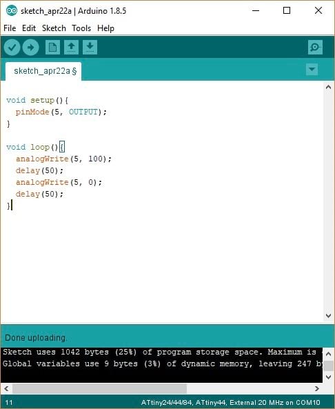
The buzzer change the sound as the voltage and signal frequency changed. I did ADC5 (Attiny44 pin number 8) as the output which connected to the buzzer. This is the only pin that I used as input or output. In the void loop, I tried the analog function which provides me with variable voltage from 0 to 5, it’s good to note that ADC5 has PWM (pulse width modulation) that can make the voltage variable by switching the output voltage on/off with specific time frames. The command analogWrite takes two arguments, the first one is the pin number and the second one is the voltage level as 8 bits from 0 to 255 (0 means 0 volts, 255 means 5 volts and so on). Then delay then turn it off then continue the loop.
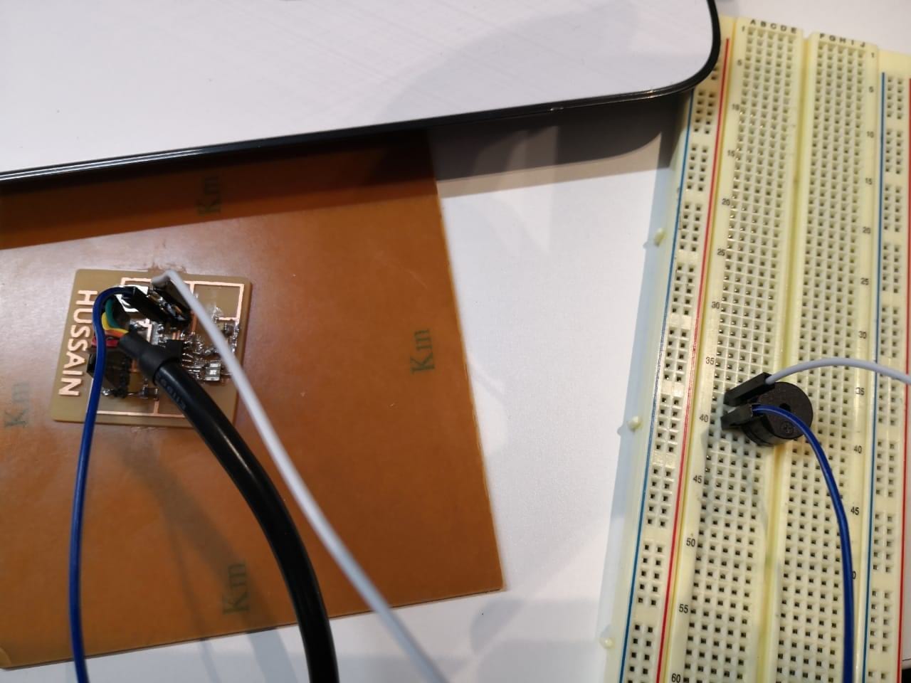
I connected the arduino to upload the code through it after connected the arduino to my board Attiny44. The code uploaded successfully.
Now, I disconnected the Arduino and connected the buzzer to my board, the buzzer has two terminals, one is the signal which is positive, the other one is GND which is negative.
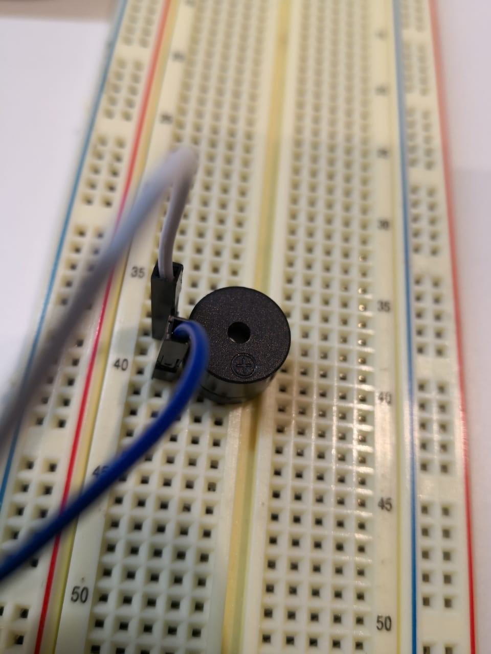
ADC5 means Attiny44 pin number 8, so I connected it accordingly /p>
Powering up the circuit using FTDI cable and record the results
To open or download file
Programing File of 7 sigment: Click Here!
Programing File of buzzer: Click Here!
Custom Board according to outputs that I have
List of components:
Part |
Value |
Package |
Library |
BUZZER |
|
02P |
con-amp-quick |
C1 |
|
C1206 |
resistor |
IC1 |
ATTINY44-SSU |
SOIC14 |
fab |
J1 |
|
1X06-SMD_RA_MALE |
SparkFun-Connectors |
PIEZO |
|
02P |
con-amp-quick |
POTENTIOMETER |
|
03P |
con-amp-quick |
R1 |
|
R1206 |
resistor |
R2 |
|
R1206 |
resistor |
R3 |
|
R1206 |
resistor |
U$1 |
LED |
LED1206 |
fab |
U$2 |
RESONATOR |
EFOBM |
fab |
U$4 |
AVRISPSMD |
2X03SMD |
fab |
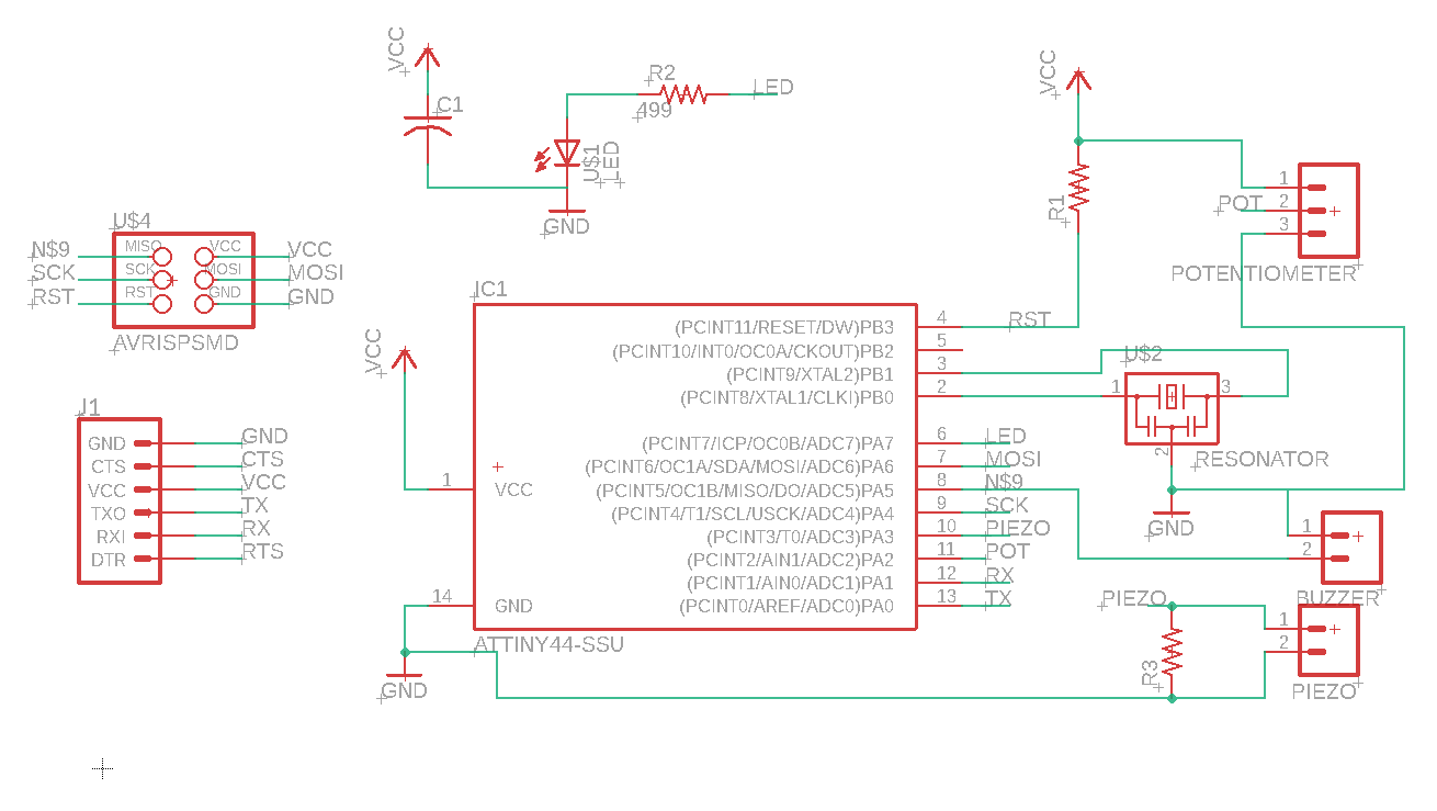
The schematic that I have done is basiclly Attiny44 based, consedering the input and output devices that I chose, which are (potentiometer, piezoelectric, Servo motor, and buzzer)
I started connecting the paths (traces) to be suitable for milling
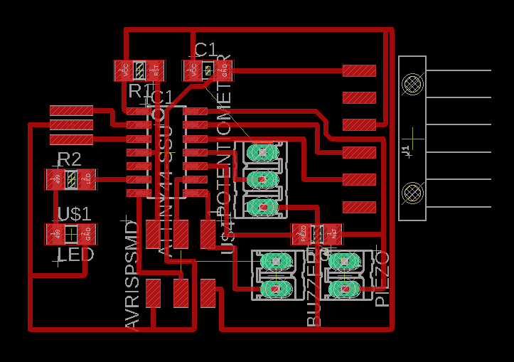
After I did the traces, I exported the traces as Dxf then converted to SVG to be vector, so it can be milled perfectly

I used Carvey machine as I did in Electronics Design week, the board is milled and ready to be soldered. I started soldering the microcontroller chip (Attiny44)
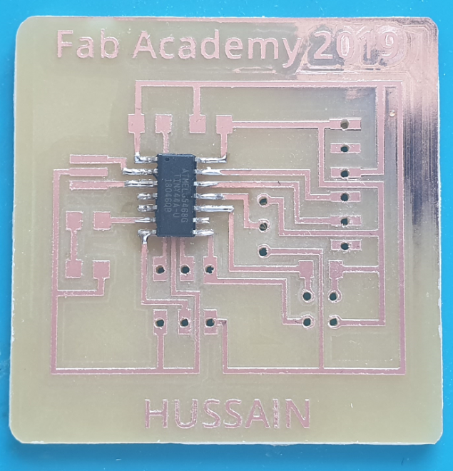
Soldring the ATtiny 44
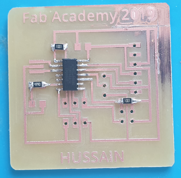
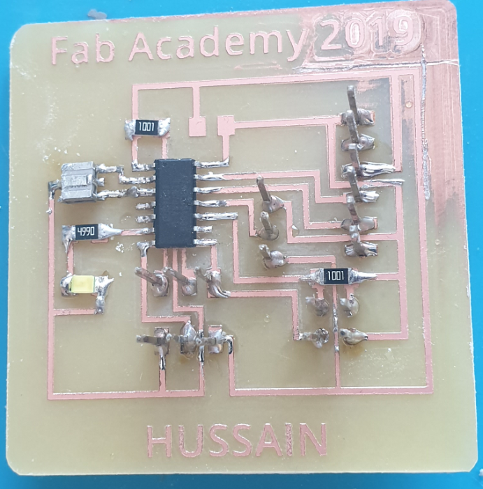
All the components
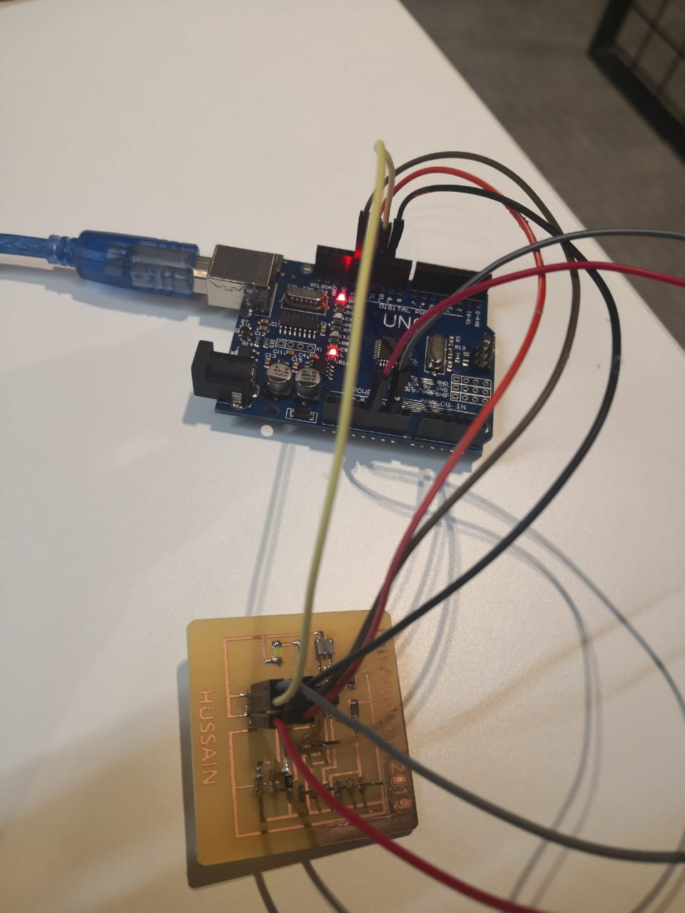
I connected the board to an Arduino to be programmed. I used the Arduino as ISP
First, burnning the bootloader after selecting the board and external clock 20MHz (you have to burn the bootloader only once)
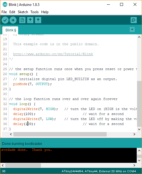
The bootloader was burend
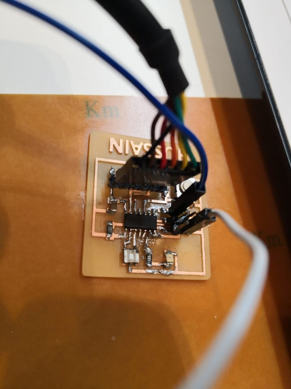
I started the first experiment which is connecting the buzzer to make a tone
buzzer output
I used the same code that I did above, but consedering the pin that I added in the design which is 5
I uploaded the code and recorded the result below
I moved to the next test, I was planning to do a fun project which is a simple game that convert the knock to motor movment. The movment will depend on the force applied. I used pizoelectric as an Input to convert the knock and servo motor as an output to move according to the knock. The servo motor has 3 pins (VCC, GND, and signal). the signal can be connected to output pin form the microcontroller
I wrote the code to measure the voltage when someone knocks, the reading will be from 0 to 1023 (10-bits) but I can not direct the value to servo as =the output voltage can be 8 bits only (from 0 to 255). I used map function to map the values from 0 to 1023, to from 0 to 255.
code and the result into next videos
To open or download file
Programing File of 7 buzzer: Click Here!
Programing File of servo with pizor: Click Here!