Networking - Final Project board & Hello board
For this week’s assignment, I will communicate between two boards I made. I will use my final project board, that uses an Atmega microprocessor, and connect it to the HelloBoard, that uses a Attiny.
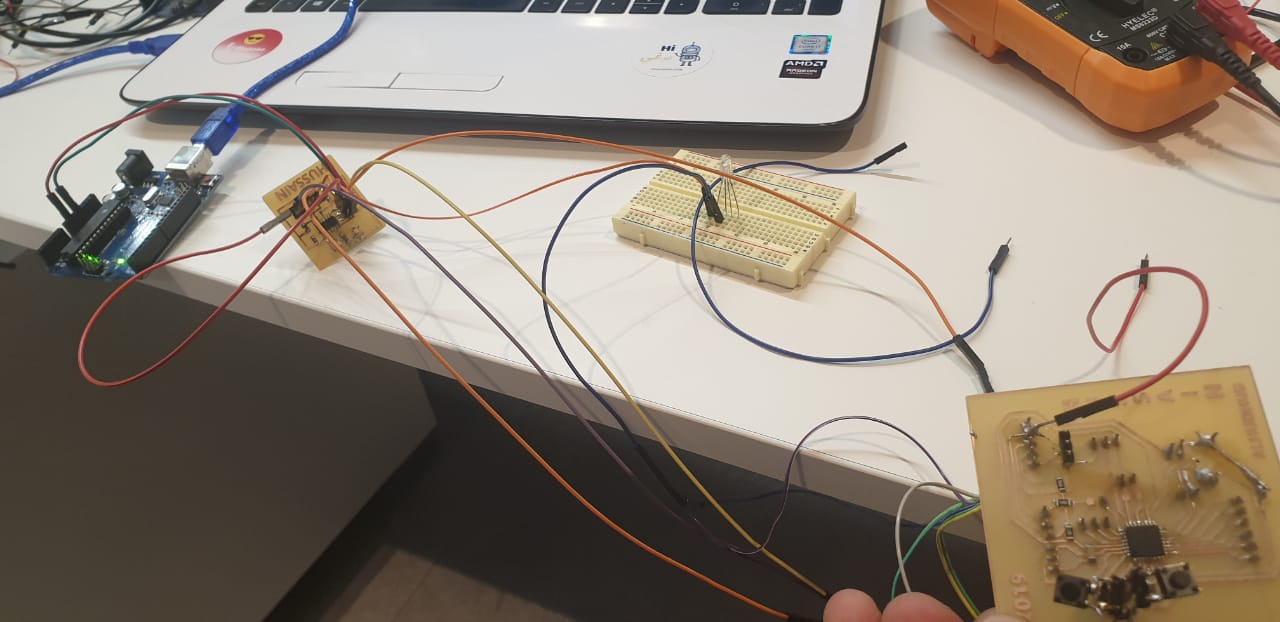
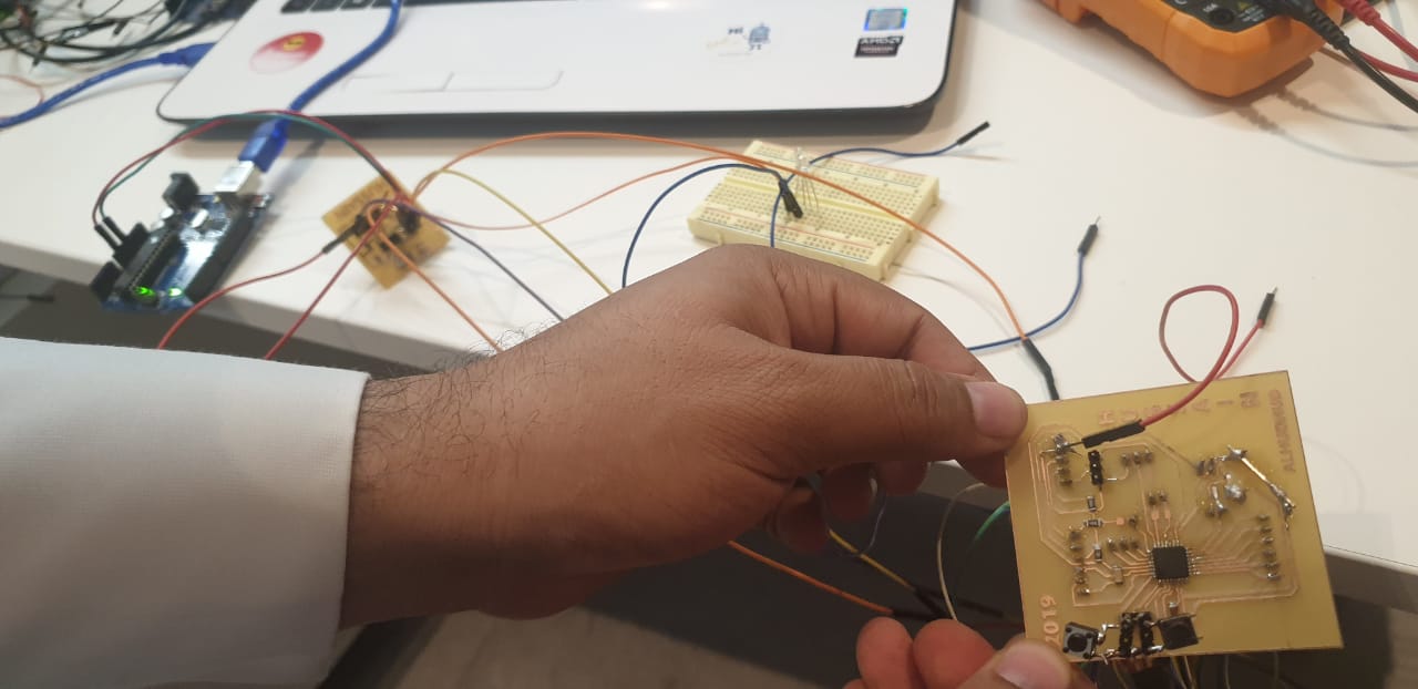
These are my boards and it's linked to my webpage documentation:
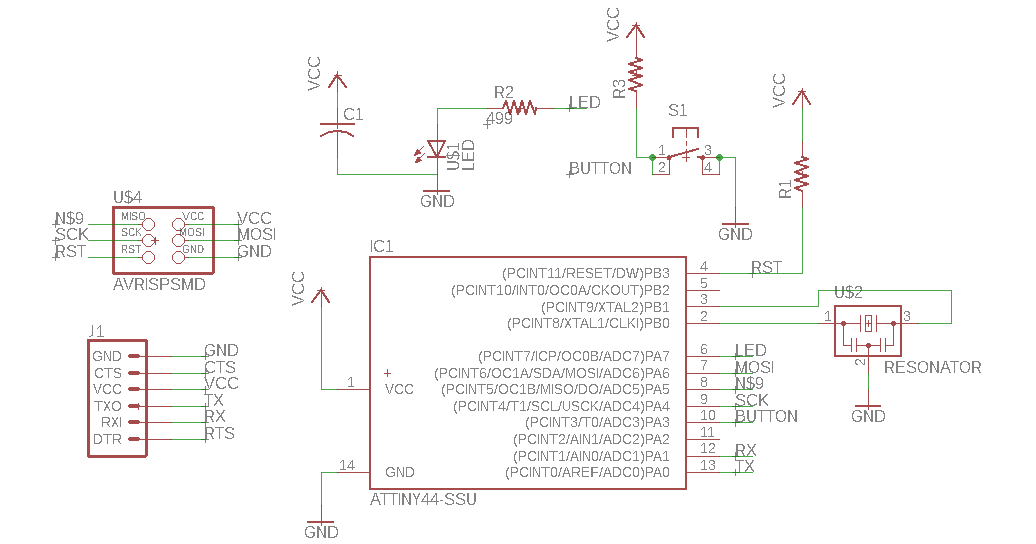
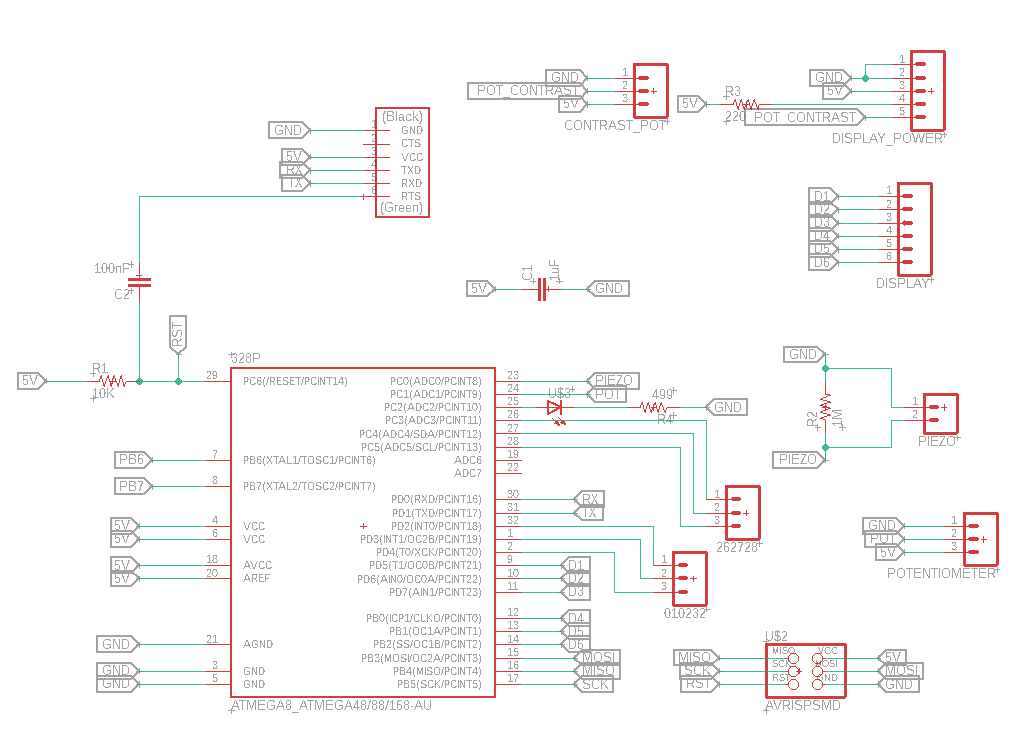
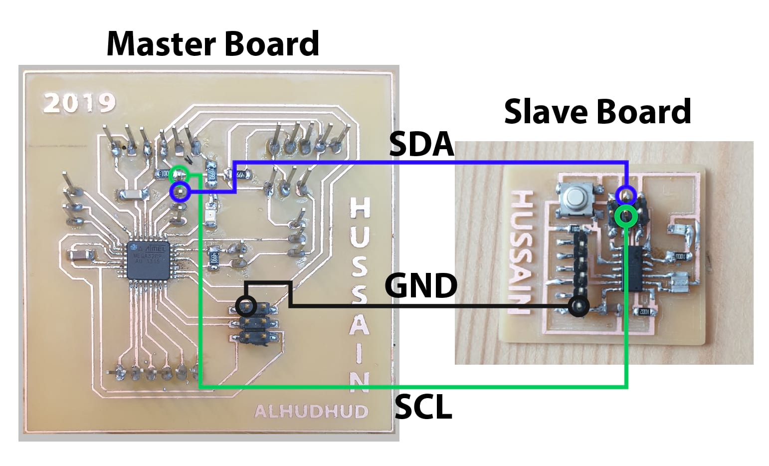
I will communicate between them using Inter-Integrated communication protocol, or more widely known as I2C. For this, the two pins I need to interconnect are the SDA and SCL from each board. In my attiny, this pins will be pins 7 and 9, and in my Atmega, It would be the pins 27 and 28.
Because my board are already done, I just use jumpers to connect the pins I need.
Now, I will do the code for the boards. I will use the Atmega board as my Master Board. For this processor, I need to import the wire.h library, which will help me use the i2c communication. As a Master, I just need to define to which slave address I want to communicate with, for which I will use a variable called address. I want to use two pushbuttons connected to my board, and depending on which one I press, I will send a different message to my slave to do a different action. To read the push buttons, I use the digital read command.
Then, In my void Setup, I just define the pins I need, and begin the wire communication. I use the set.Clock method from the wire.h library to slow down a little the communication, to make sure the communication works properly.
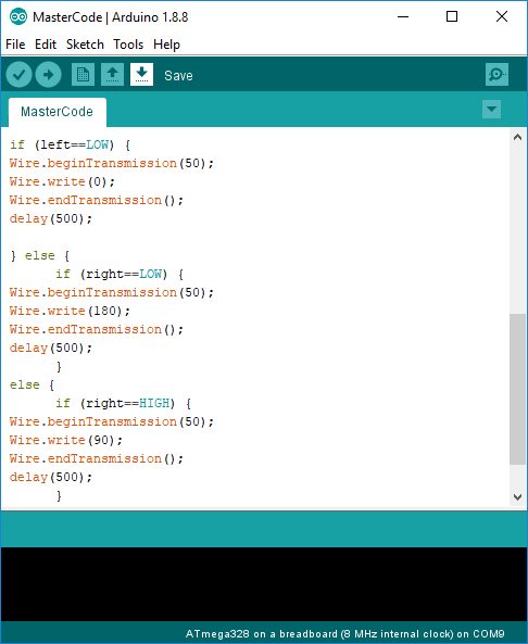
Then, in my void Loop, I will read the state of the two digital inputs I selected for my pushbuttons, and depending on this, I will begin the transmission to the variable in the address, and send an specific message. If no push button is pressed, I will send a different message, and wait for half a second to repeat the loop.

#include <TinyWire.h>

byte address = 50;
const int left = digitalRead(3);
const int right = digitalRead(4);

void setup() {

//pinMode(13,OUTPUT);
pinMode(3,INPUT_PULLUP);
pinMode(4,INPUT_PULLUP);
Wire.begin();
Wire.setClock(10000) ;

}

void loop() {

int left = digitalRead(3);
int right = digitalRead(4);

if (left==LOW) {
Wire.beginTransmission(50);
Wire.write(0);
Wire.endTransmission();
delay(500);

} else {
      if (right==LOW) {
Wire.beginTransmission(50);
Wire.write(180);
Wire.endTransmission();
delay(500);
      }
else {
      if (right==HIGH) {
Wire.beginTransmission(50);
Wire.write(90);
Wire.endTransmission();
delay(500);
        }
     }
  }
}
Now, for my Slave board using the attiny, I need to use a different library, to use the same communication protocol but specifically for my processor. This is the TinyWire.h library
I begin by importing this library to my code, (assuming its already downloaded and added to the arduino ide from here.
As a slave, I need to define the address for my board, which is 50, so I create a variable with this data, and then create another one to store the message I will receive.
In my void setup, I assign the address by using the begin command, and then call a method “onI2CRecieve” to execute some commands if a message is received. Additionally, I define 2 digital outputs in pins 7 and 5 to control 2 LEDS.
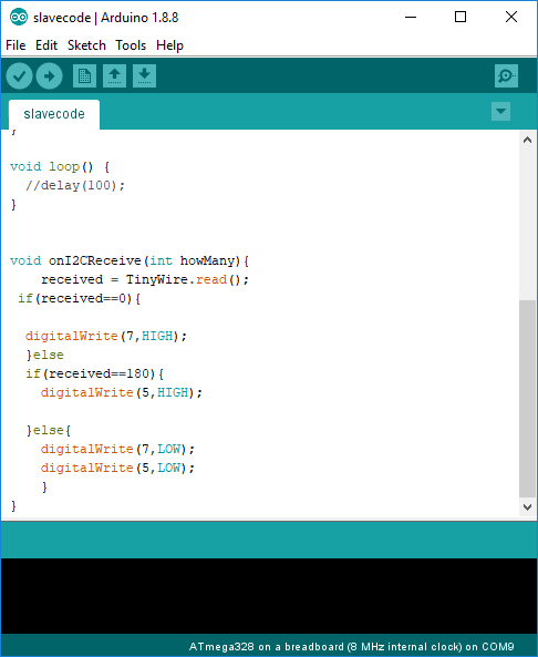
In this code, I will leave the void loop empty, as I don’t want anything executing all the time, and will create a new void method that will execute only when a message is received.
In this method, I save the message received in the variable received, and then, just compare if the message is 0 or 180, to turn on one of the leds, and if the message is different, I will just leave both off.
This is my complete code for the slave.
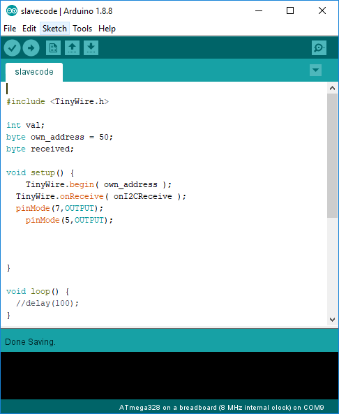
#include <TinyWire.h>
int val;
byte own_address = 50;
byte received;
void setup() {
TinyWire.begin( own_address );
TinyWire.onReceive( onI2CReceive );
pinMode(7,OUTPUT);
pinMode(5,OUTPUT);
}
void loop() {
//delay(100);
}
void onI2CReceive(int howMany){
received = TinyWire.read();
if(received==0){
digitalWrite(7,HIGH);
}else
if(received==180){
digitalWrite(5,HIGH);
}
else{
digitalWrite(7,LOW);
digitalWrite(5,LOW);
}
}
In addition, here, you can see the communication working.