Electronics Design
redraw the echo hello-world board
Using Eagle Software
It was interesting to use Eagle Software for the first time. Step one was reading the tutorial carefully to learn the concept behind this assignment. Next, I did a little practice following the tutorial "echo hello-world board" and I faced one thing that gets me a little confused about how search in the library to find the right components. Later, I figured out that I must open the library before to starting the dropdown components. By the way, I had to download fab.lb which is provided by fab network. It also maintains a library, so that I can easily find the components. All you need to open the fab.lb is copying files to the director library of Eagle and open the software then go to library on the left list, right click and choose to use all.
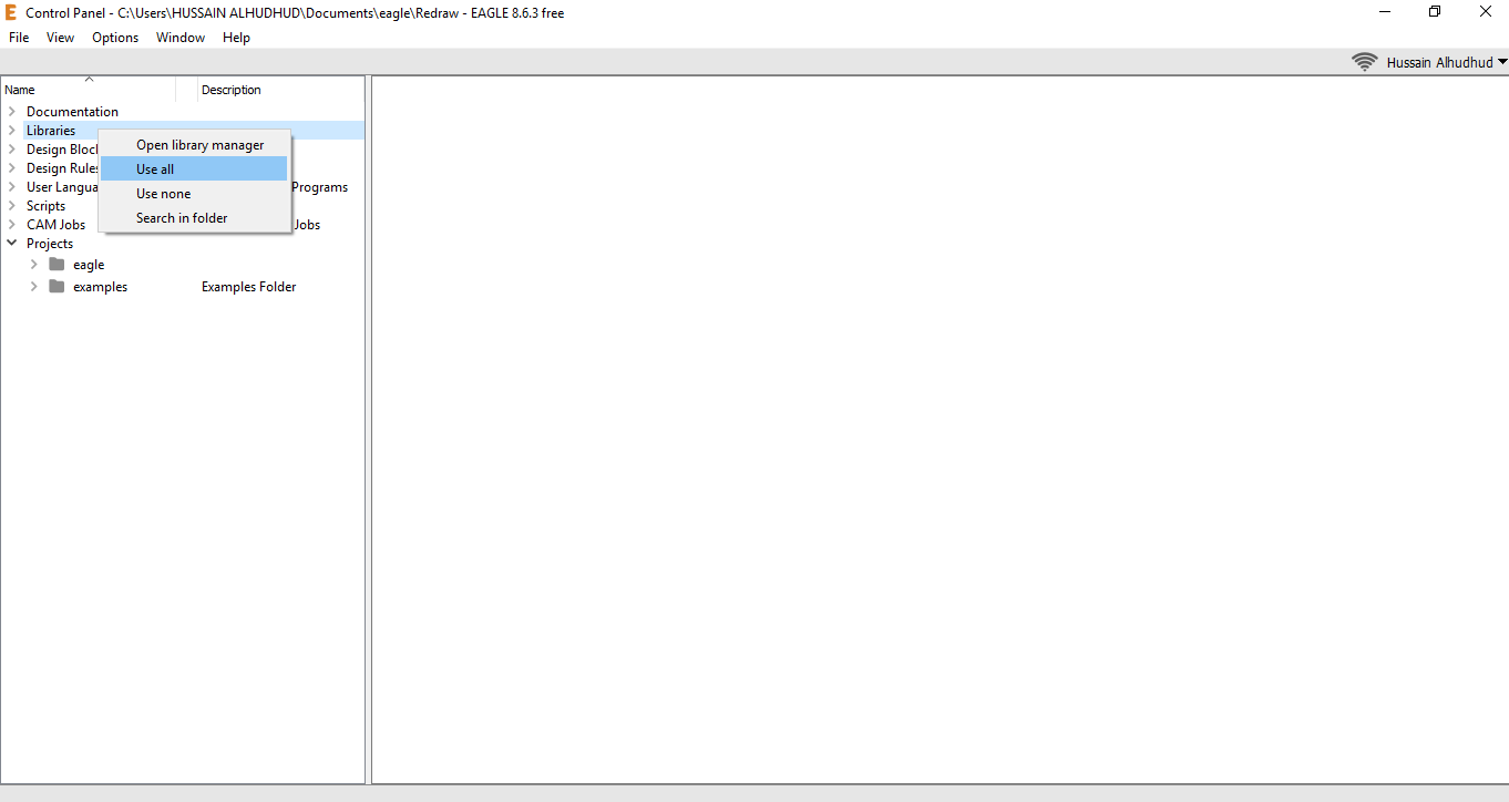
After copy the library to the director
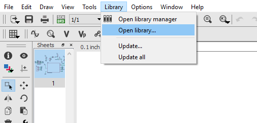
browsing the library to select fab.lb
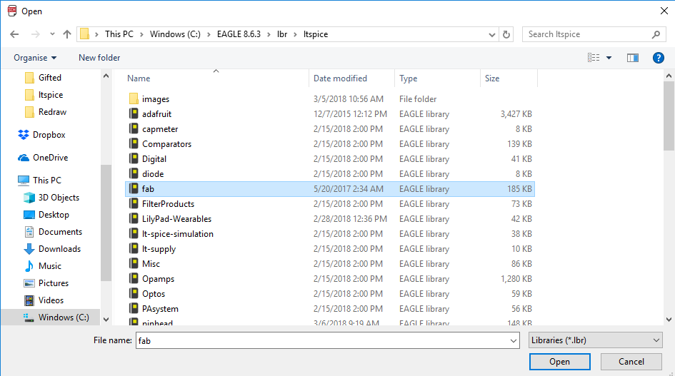
browsing the library to select fab.lb
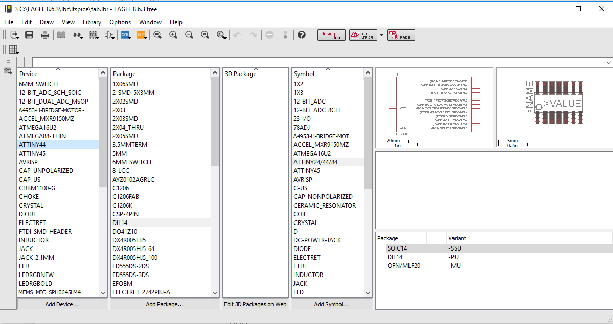
Write down the device name to easily dropdown the components later
Eagle software
Draw the schematic and the board
First of all, create a project then create new schematic. On the schematic, you will add the following components:
- ATTiny44 and to find it we write down (*ATTINY44*)
- 1 2x3 pin-Header
- 2 10Ω Resistance and to find it we wirte down (*RES-US*) the look in to R1206
- 1 499Ω Resistance
- 1 uF Capacitor and to find it we wirte down (*CAP-UNP*) the look in to C1206
- 1 6 pin-Header-Male and to find it we wirte down (*FTDI BASIC*) then look in to 1x06SMD
- 1 Button
- 1 LED
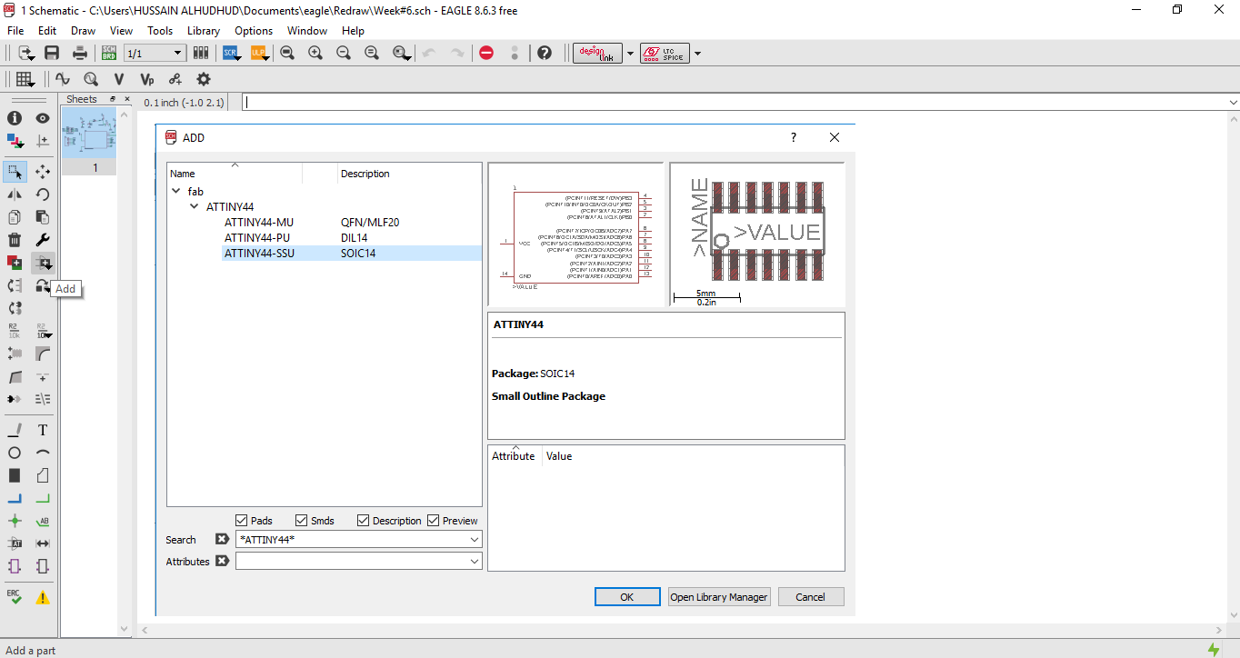
search and the components to the schematic
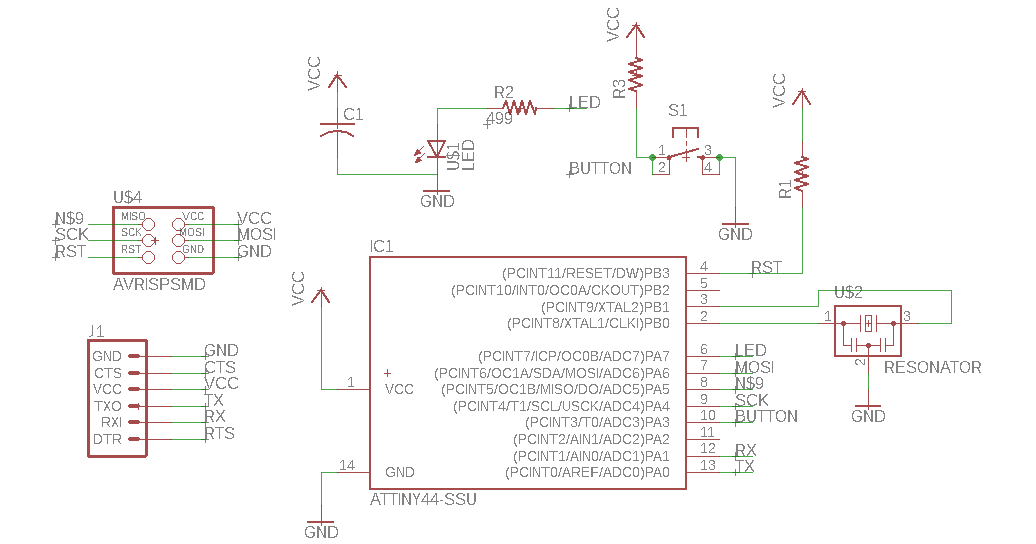
The schematic after adding all the components
now go to file > switch to the board
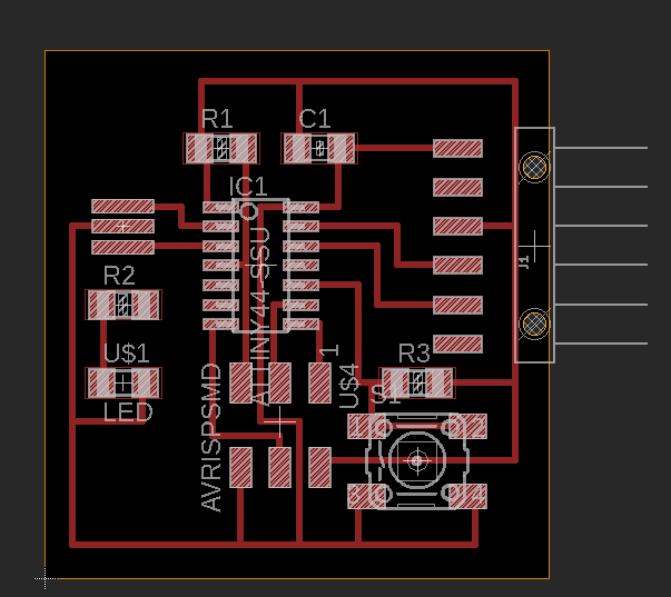
In this stage, we move, rotate, and wired the components
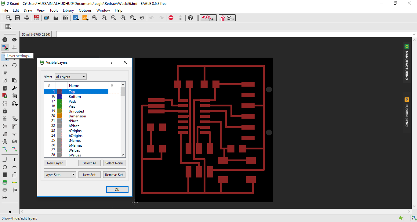
On the layer settings > select top
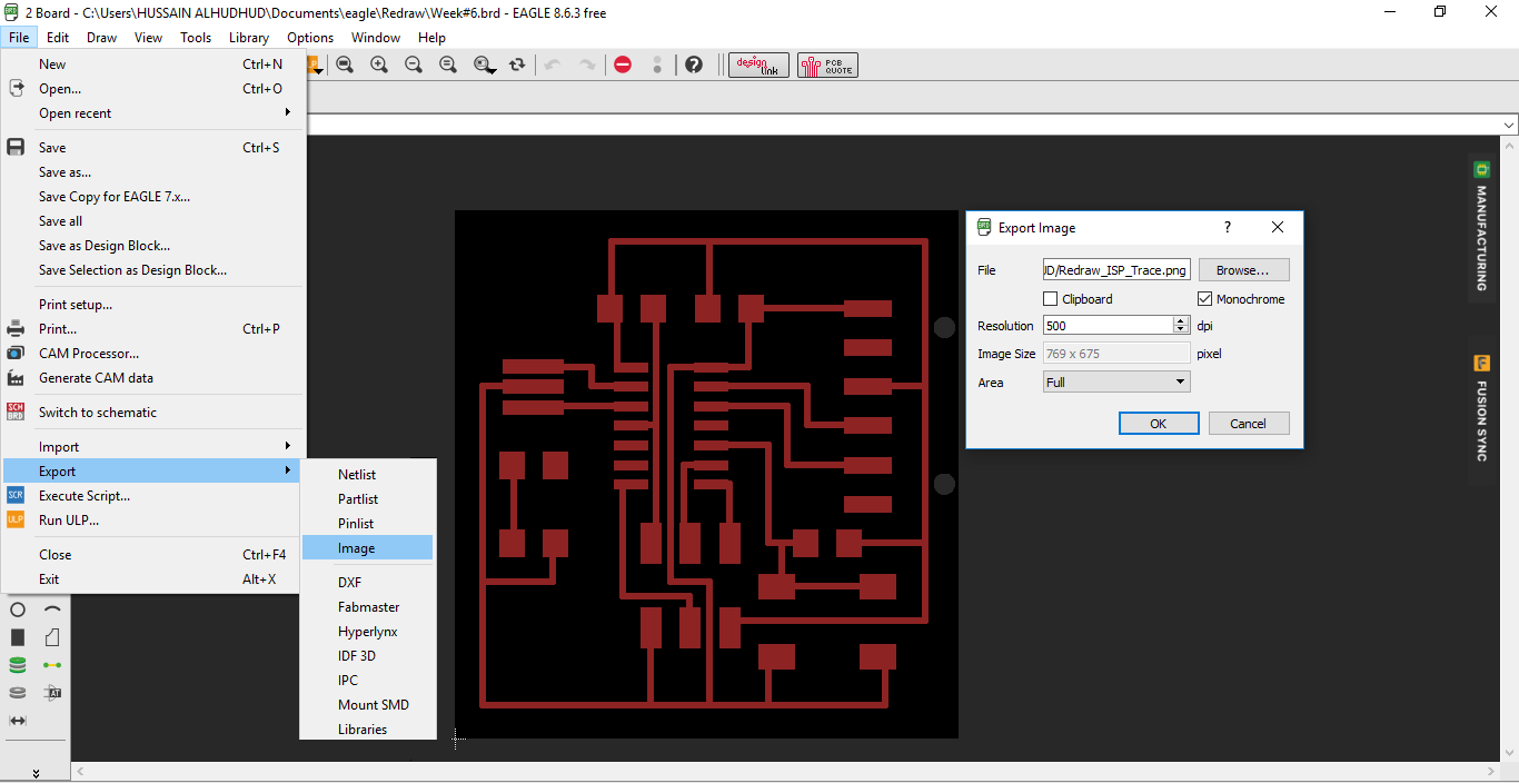
Save the board as an image for a resolution 500 dpi and check in Monochrome, even the image become white and black
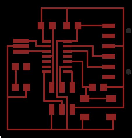
The board
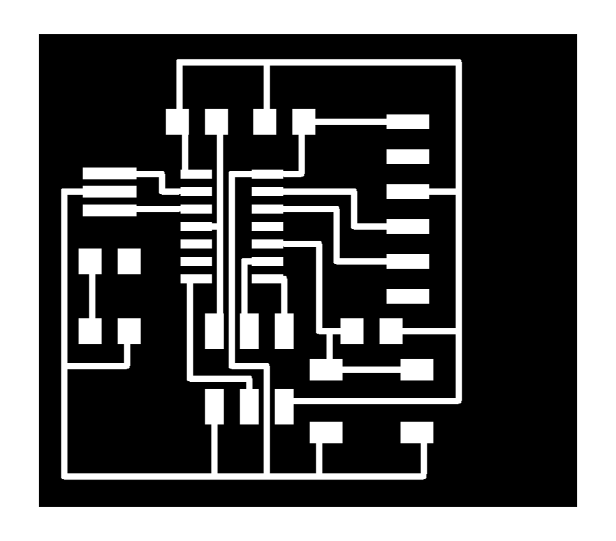
The ISP Trace Layout
Download: Trace Layout

The ISP Cut Layout
Download: Cut Layout
Download: SVG file
Download: Eagle file
Eagle software
Draw the schematic and the board
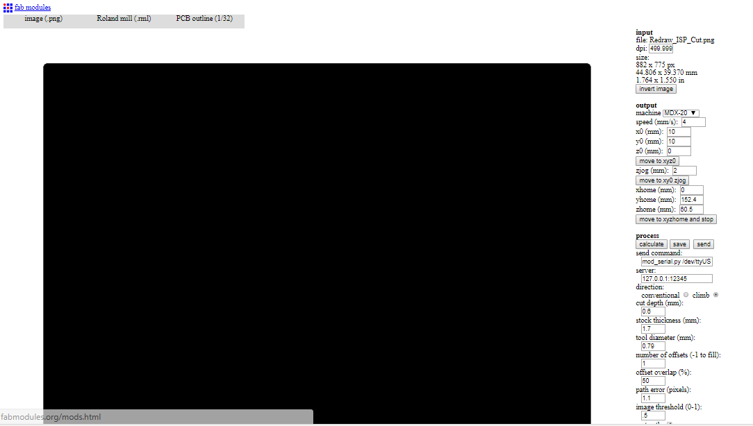
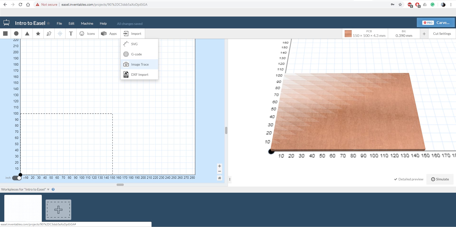
Once you finish installing the Fab Module MDX-20 will be able to open the web page of Fab Modules

Inserting the Trace Layout
- Select the image(.png) for the ISP Trace layout as png
- Roland mill (.rml)
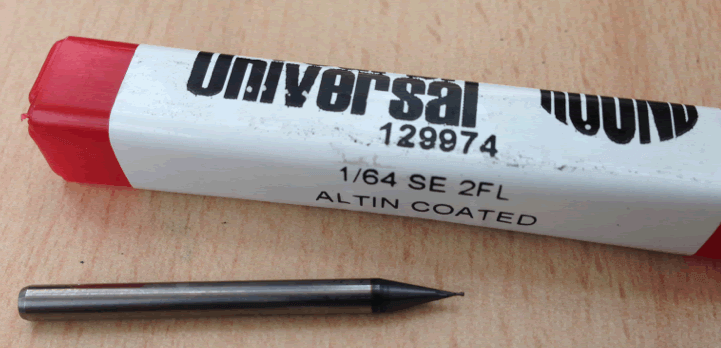
- PCB traces (1/64)
- In the output machine choose the MDX-20
- Write down your xyz 0 axis
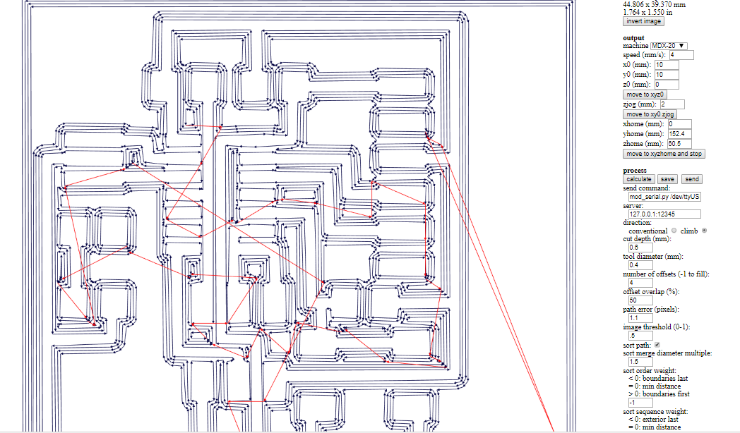
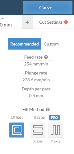
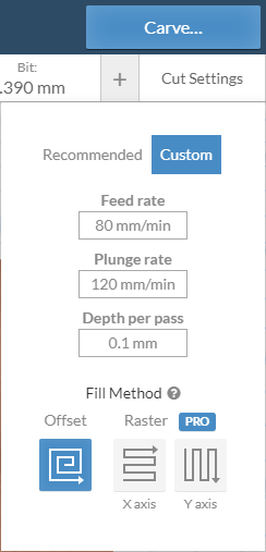
Calculating to milling the board
The Instruction to cut the ISB
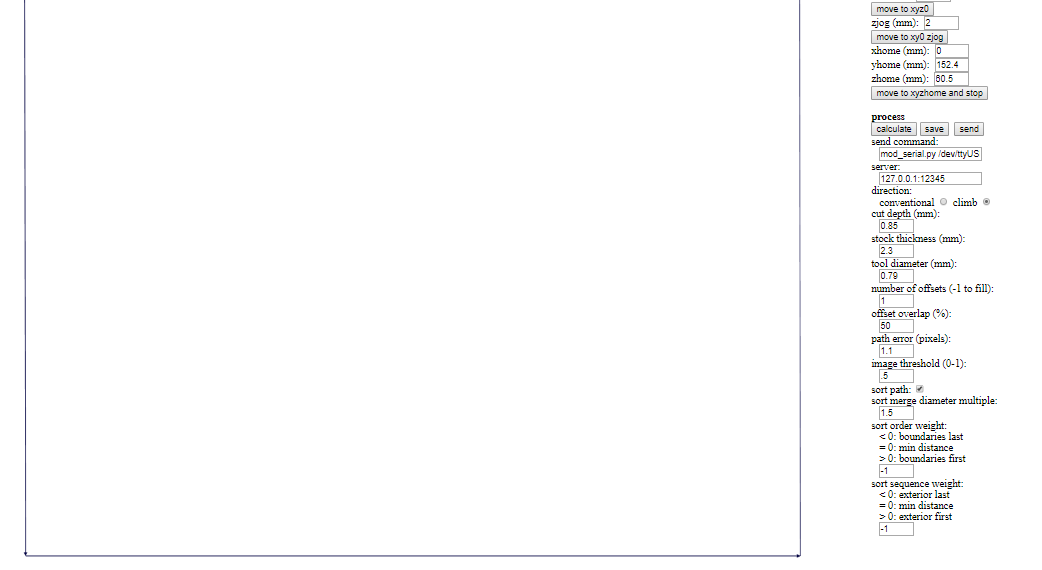
the cut depth = 0.85 mm
The stock thickness = 2.3 mm
Calculate and send to machine
After trace the layout for the ISP
_________________________________________________
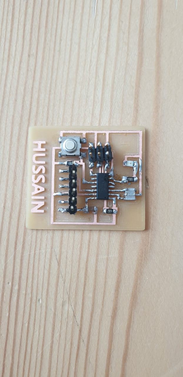
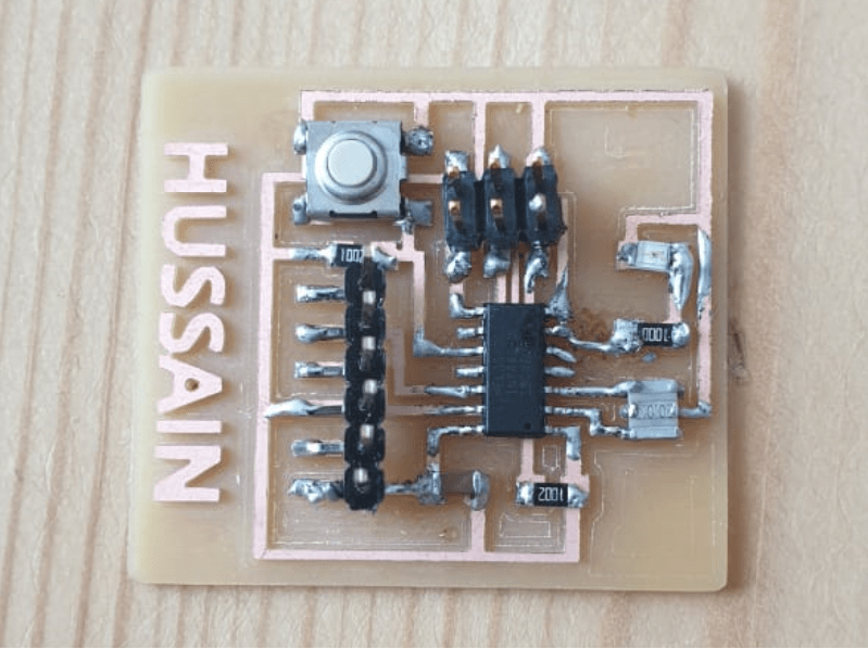
Soldering the ISP
Using SMD Components
The Electronics Components that used for the module:
- 1x Attiny 44
- 1x 499 ohms
- 2x 10Ω Resistance
- 1x uF Capacitor
- 1x 2x3 in pin-header
- 1 6 pin-Header-Male
- 1x Button
- 1x LED
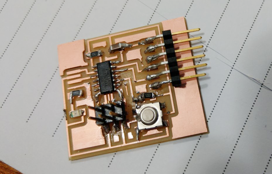
It takes one hour to finalize the soldering
_________________________________________________
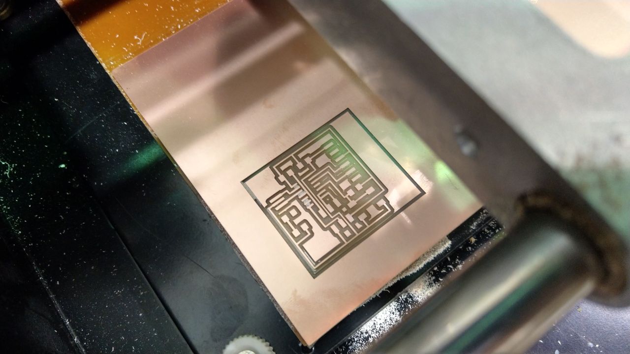
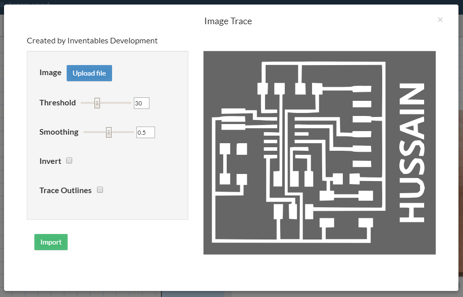
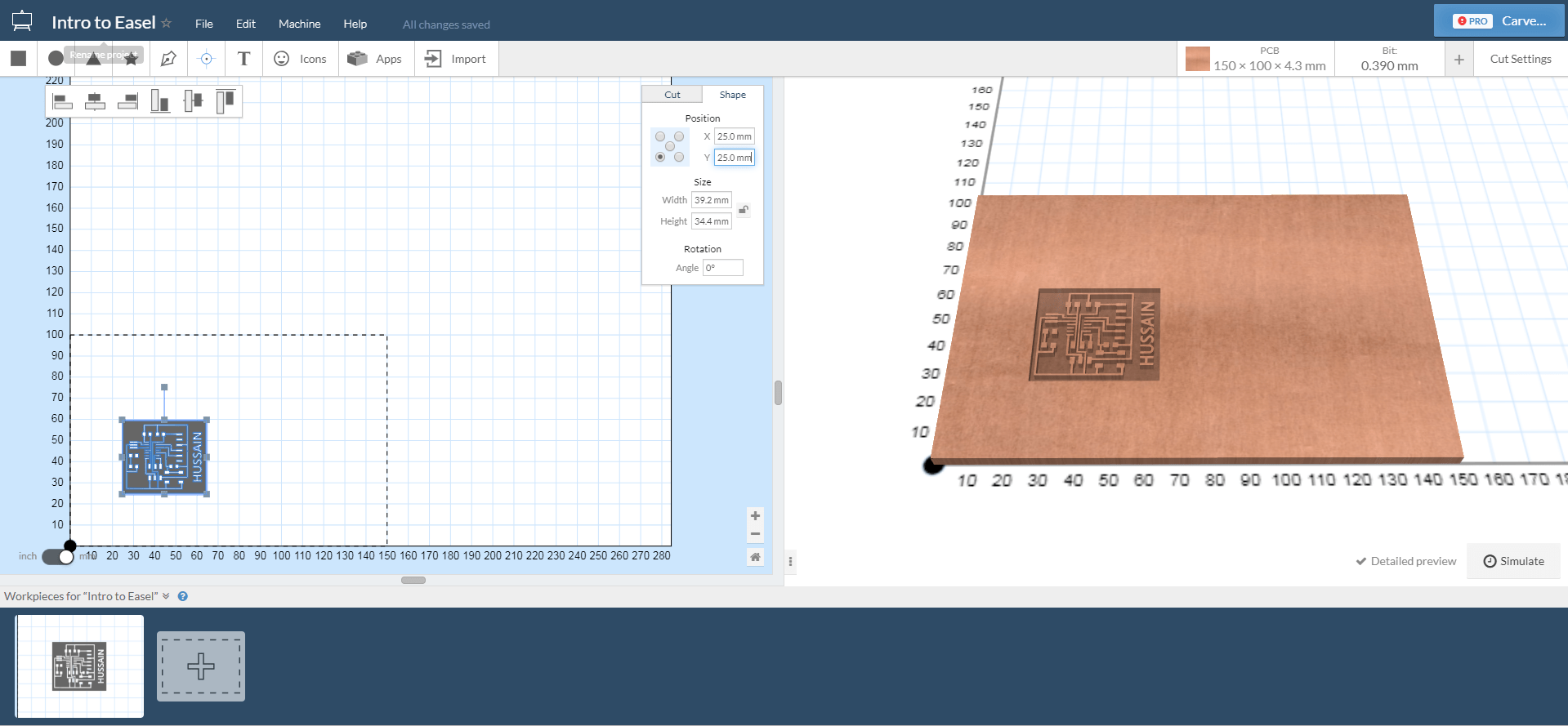
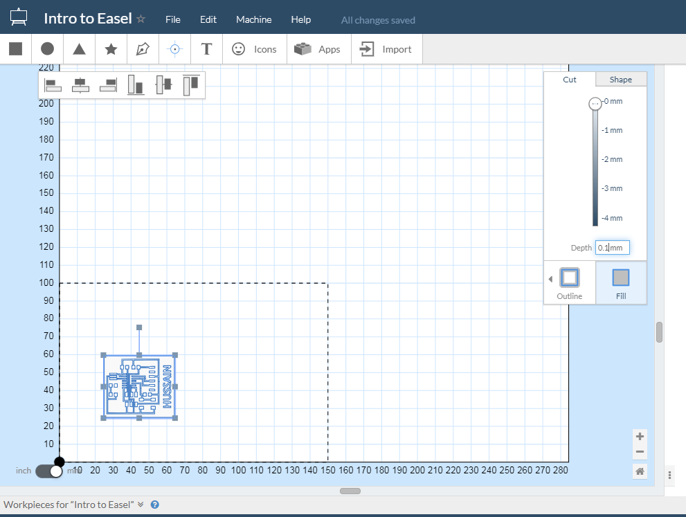
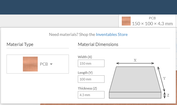
Redo The board
Using carvey cnc machine
The Electronics Components that used for the module:
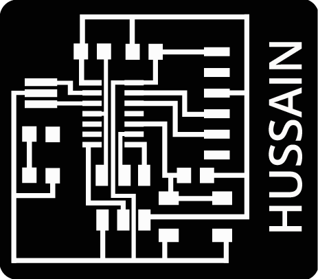
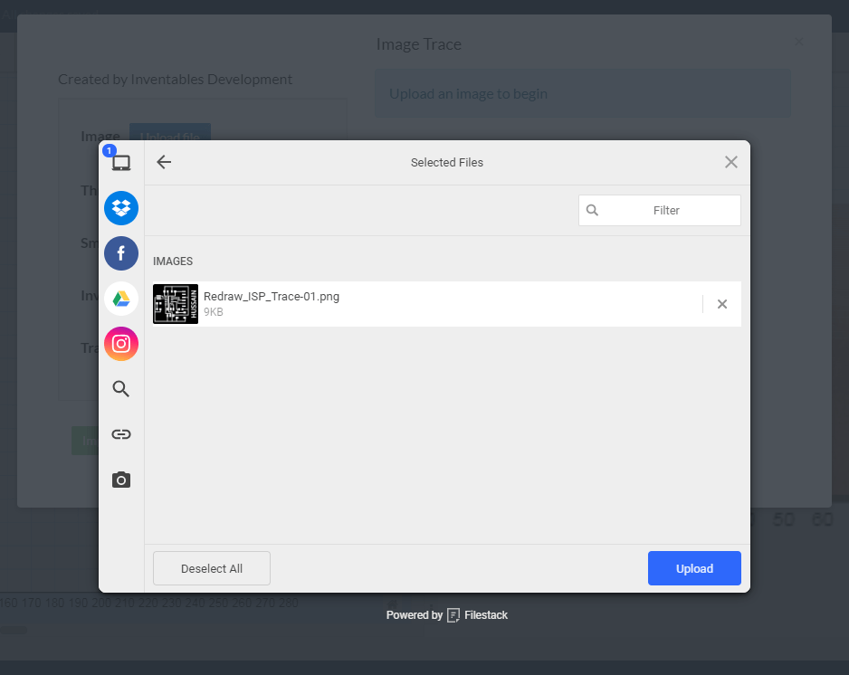
I have add my name to the ISP Trace Layout

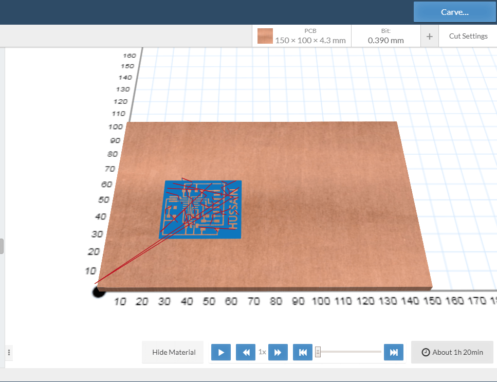
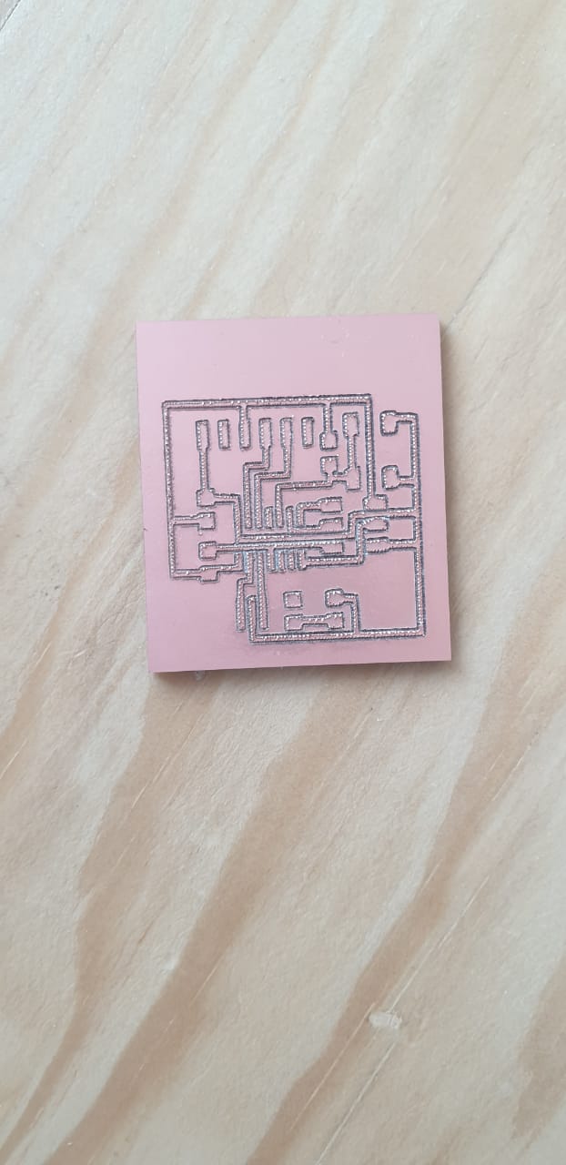
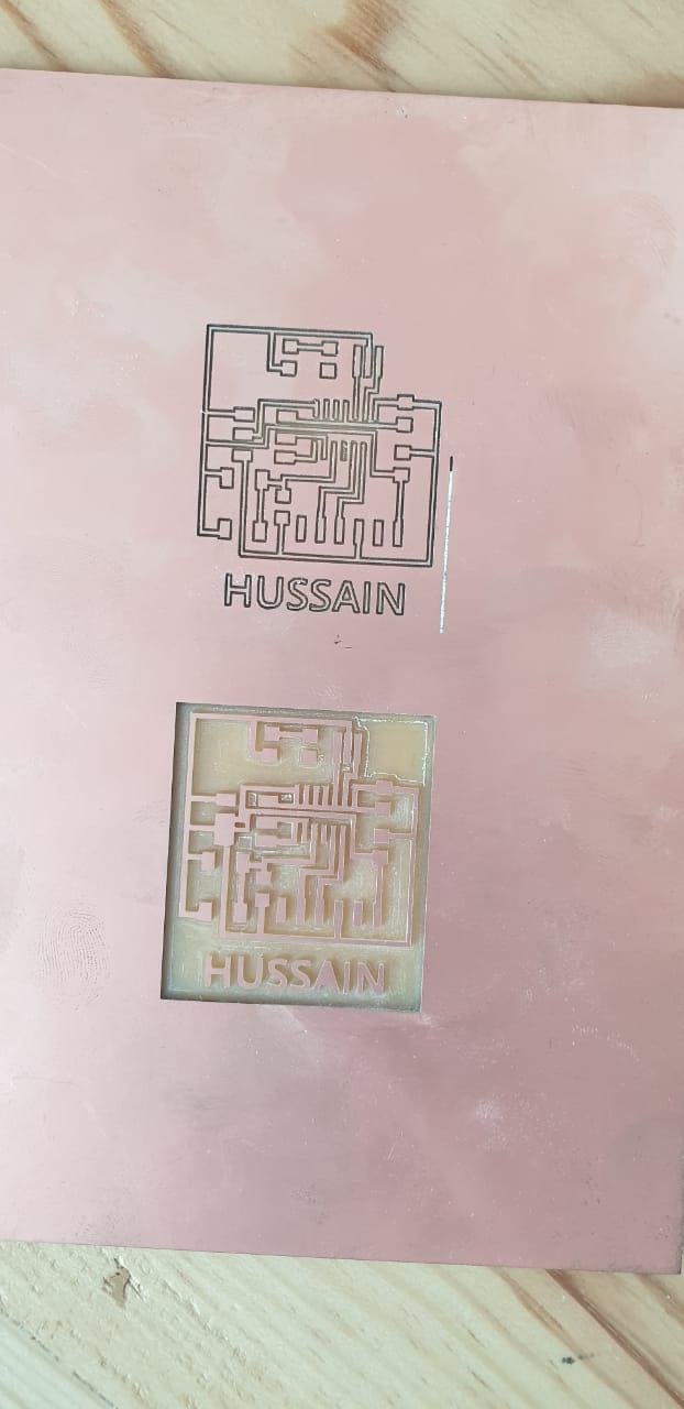
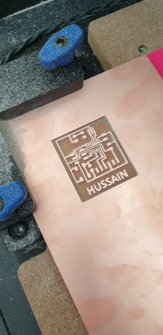
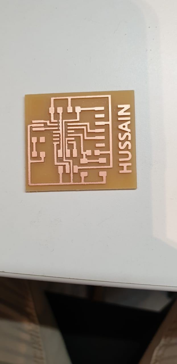
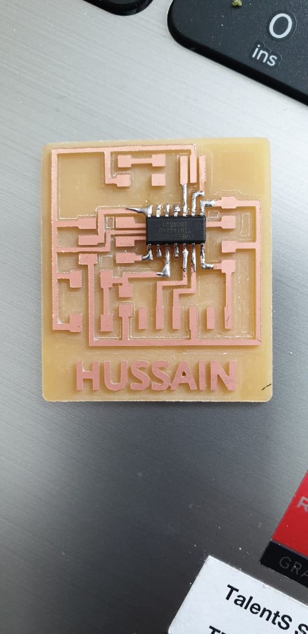
Final results
Testing the PCB (Program it)
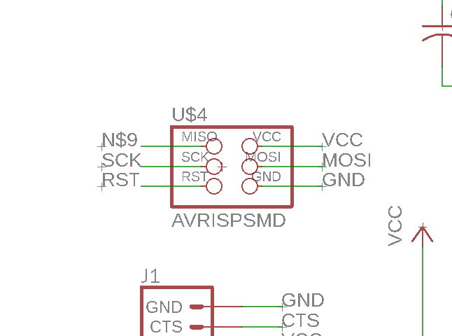
schematic diagram regarding hello board
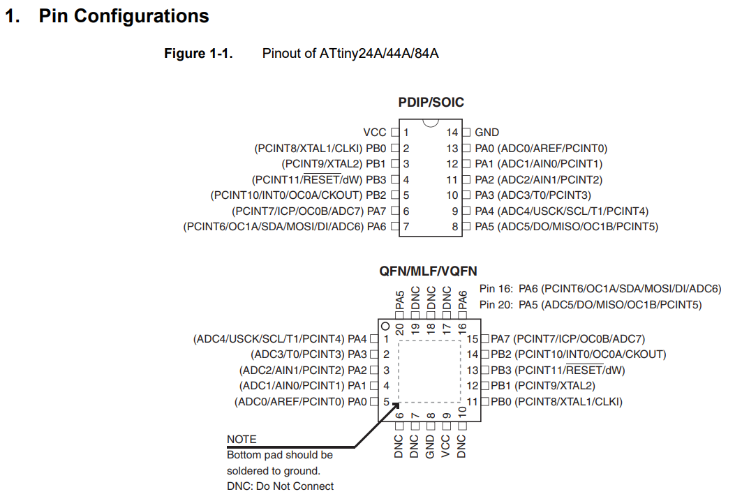
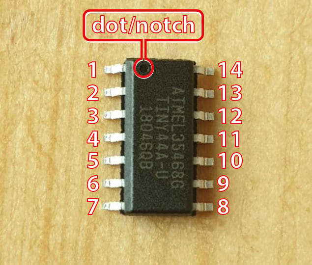
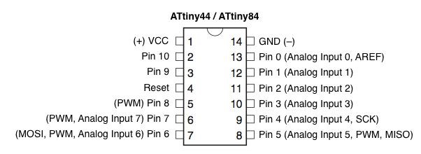
Reading the microcontroller data sheet
Connection diagram pins to be able to programme the circuit
a step before program it
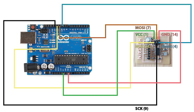
After obtaining the microcontroller pin diagram and checking the Arduino pins, I connected two boards together as the following:
Arduino Pins |
Attiny44 Pins |
5v |
1 (VCC) |
GND |
14 (GND) |
10 (digital pin) |
4 (Reset) |
11 (digital pin) |
7 (MOSI) |
12 (digital pin) |
8 (MISO) |
13 (digital pin) |
9 (SCK) |
Note: to determine the microcontroller pins, you have to see the dot or notch (in Attiny44 there is a dot) and you can count the pins as shown below:
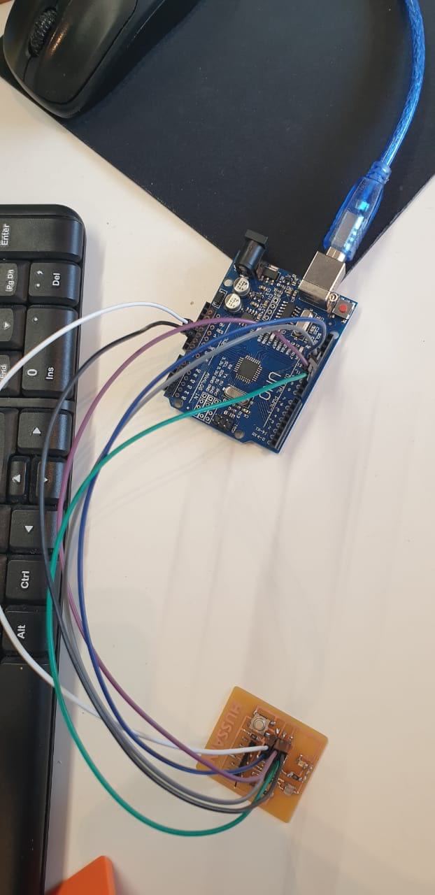
I’m going to use jumper wires (male to female) to connect the boards as I mentioned above and as the diagram that I have done:
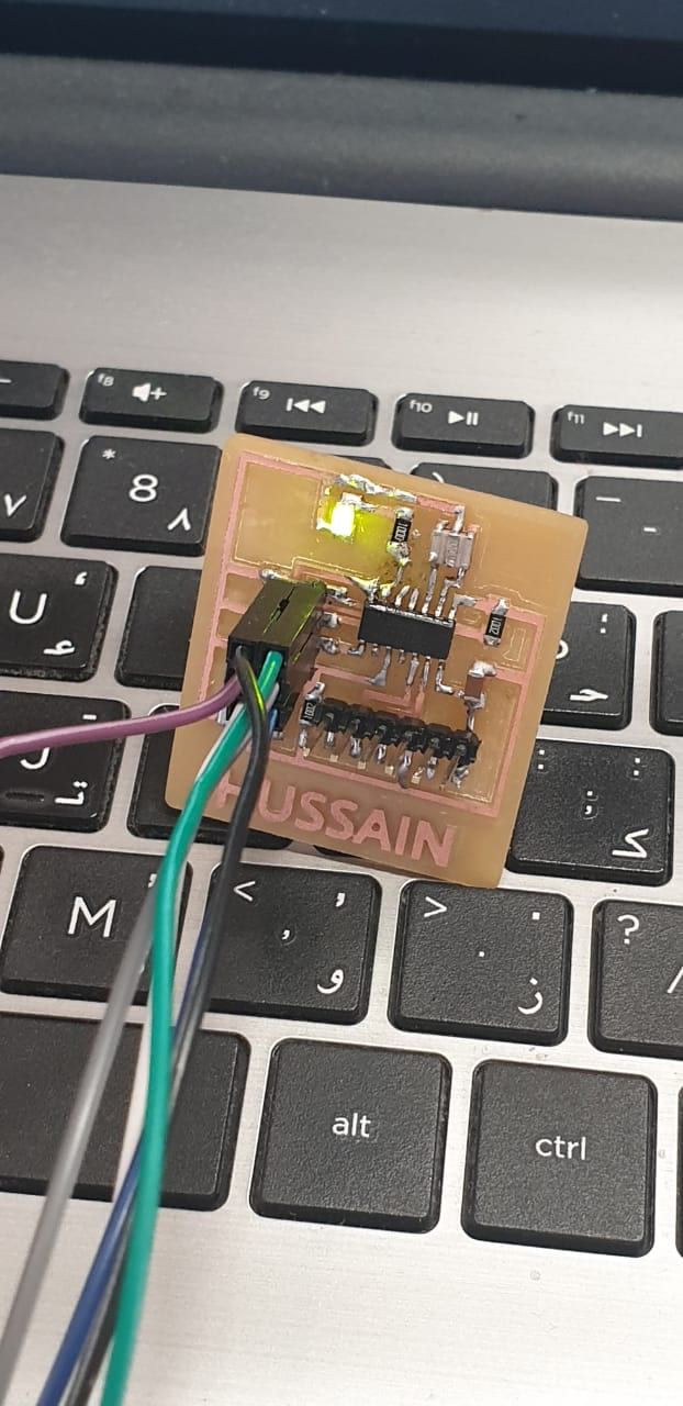
The circuit after doing the connection using jumper wires:
Then, and before connecting the circuit to the laptop to do the programming, I have to check the IDE program that I have if the Attiny boards are defined or not. I checked by clicking on Tools>>Boards but it’s not installed. To do that, I copied the following link:
https://raw.githubusercontent.com/damellis/attiny/ide-1.6.x-boards-manager/package_damellis_attiny_index.json
And I clicked on file>>preferences
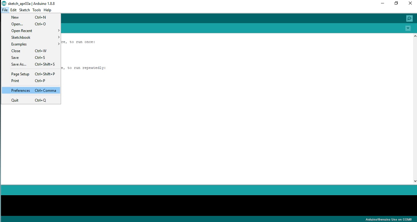
And paste the link there to define the boards packages from the link
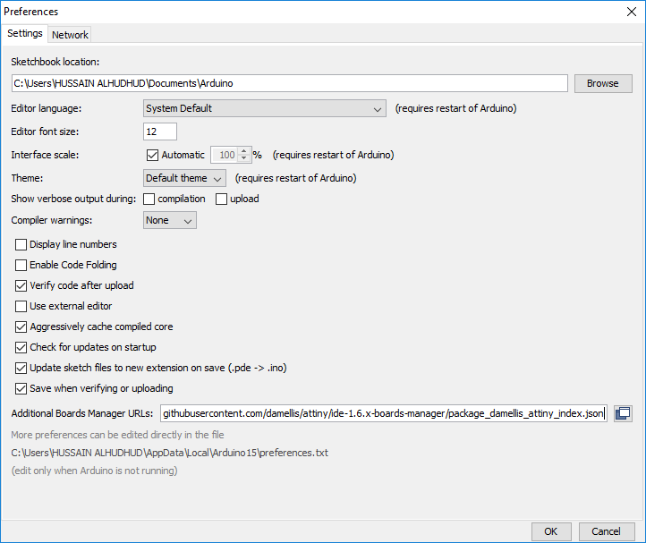
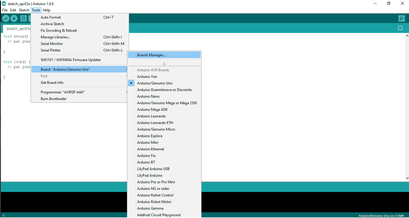
Clicking OK. I closed the program and run it once again to check the updates. Now, I should install the boards packages called Attiny. To install it, I selected Tools>>Boards>>Boards Manager
I searched using the word Attiny, it’s only one package to install, I clicked on install
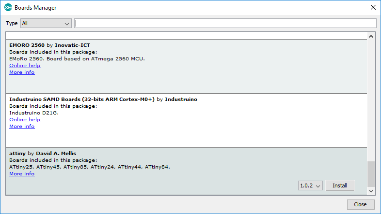
And I saw “installed”. Now I closed the program one more time and I checked the boards once again, It’s there
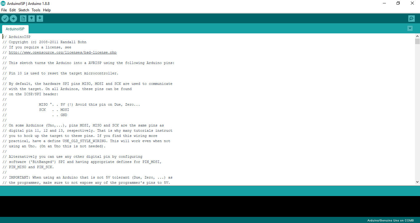
As I planned to use the Arduino Uno as ISP, I have to upload the code that makes the Arduino ready to transfer the upcoming codes to my microcontroller board. I selected the board Uno from Tools>>Boards. Then selecting the code that already exists on the same program from File>>Examples>>ArduinoISP>>ArduinoISP
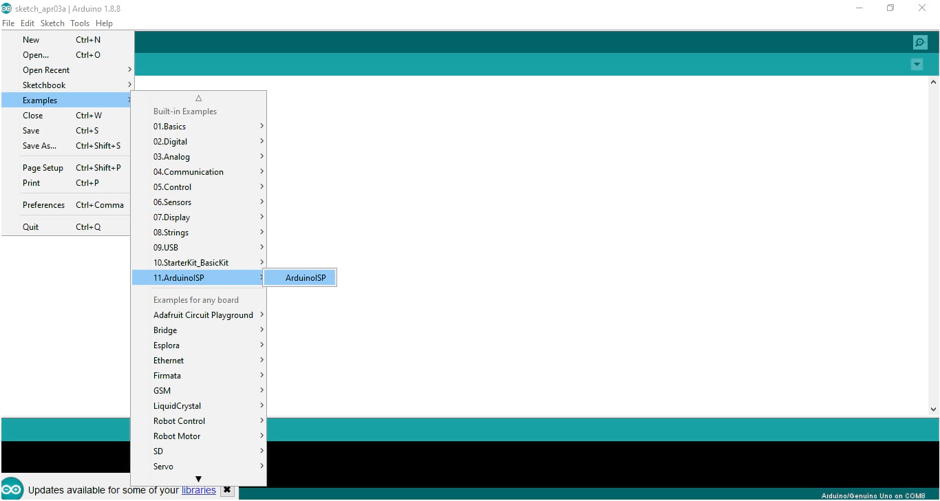
I opened the code, and finally before I upload the code check the port from Tools as well. It should be defined and marked as one of the com’s
To upload any code, I can verify it at first by clicking on the icon True ![]() , to make sure the code is correct before uploading it. I uploaded it by clicking on the icon right arrow
, to make sure the code is correct before uploading it. I uploaded it by clicking on the icon right arrow ![]()
I can see now uploaded successfully. I noticed nothing but this notification. But now the arduino is ready to transfer the code to the board that I made a couple of weeks ago.
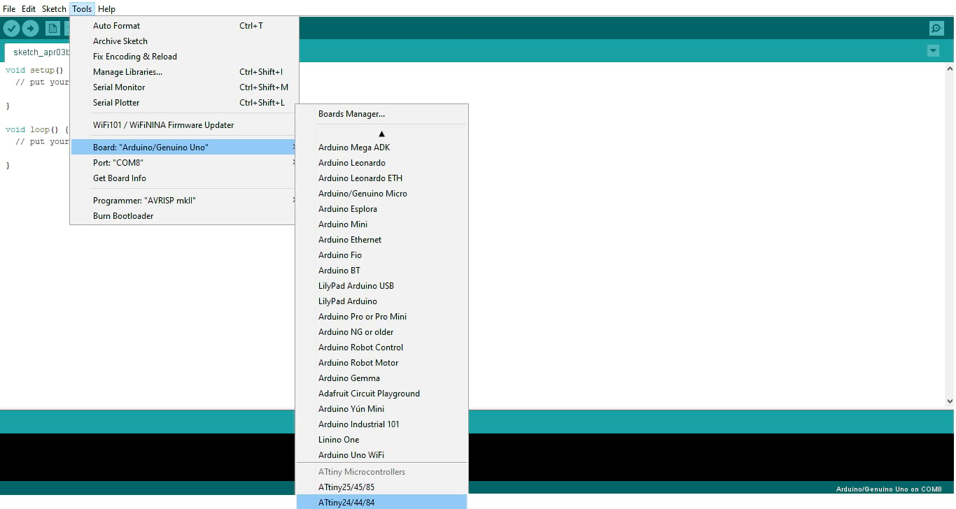
Now, I have to change the board as I’m going to program the board (Attiny44 microcontroller). I started by selecting the board that I installed from Tools>>boards>>Attiny 24/44/84
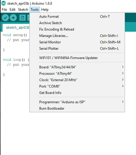
Now I checked the rest settings, as I used Attiny44 and 20 MHz crystal. In this case and as I mentioned the Arduino acted as programmer, in other words it acts as ISP. So, I selected the programmer from Tools>>Programmer>> Arduino as ISP
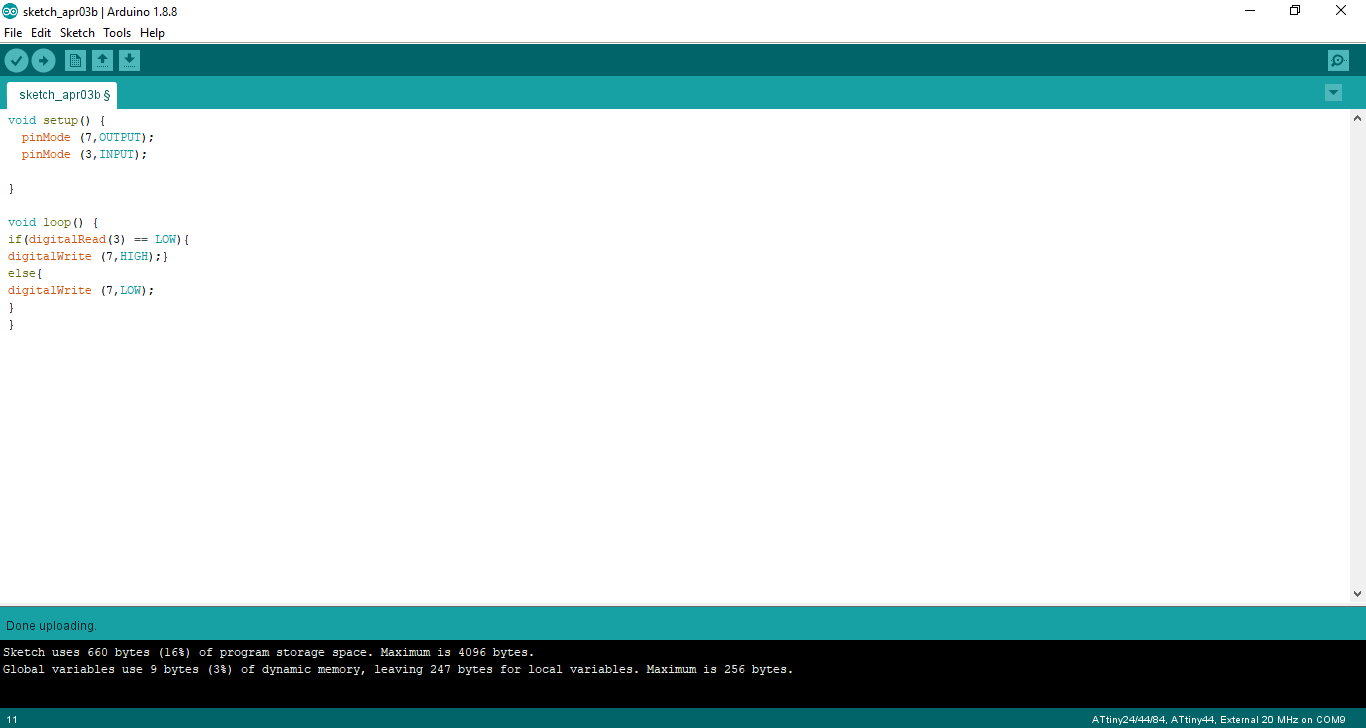
Now, everything is ready in terms of the program preparation to start uploading the codes through the Arduino Uno board to the Attiny44 hello board. Looking back to the Attiny44 data sheet and to the board that I have made, the Resistor and LED connected to Attiny44 pin 6 but this pin is called 7 in terms of programming if I wish to call or communicate it as mentioned in the pin diagram.
So, I prepared the code to turn on the LED only, by defining the pin the the void setup and turning it on in the void loop
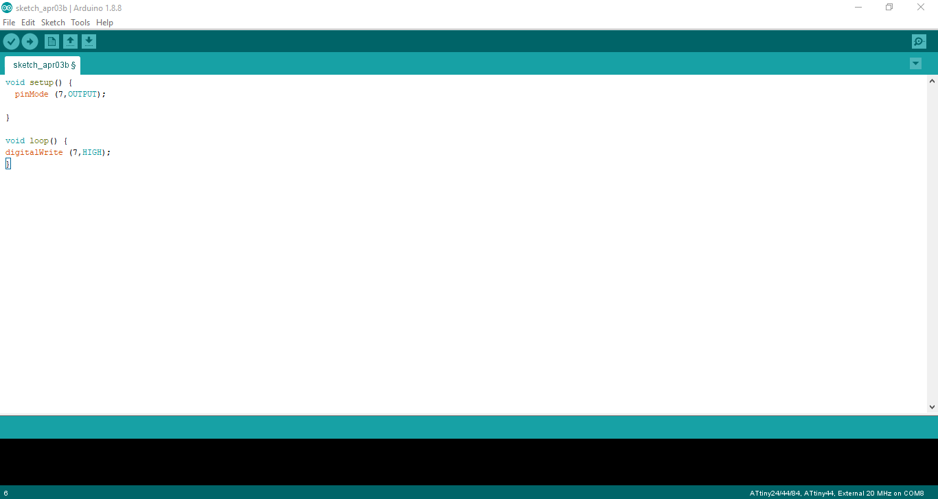
Note: The arduino programming language is C-based and I have two main loops, the first one called void setup (to identify any input/output pins and do initialization for some parts) the second one is called void loop (to do anything and it will run continuously repeating)
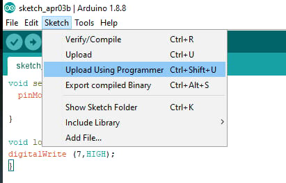
To upload the code, I clicked on the Sketch>>Upload using Programmer
I saw the notification done uploading. And the LED has turning on.
I tried to make blinking by using delay function, as the following code
So, it’s mainly 4 commands the first one to turn the LED on, the second one is to wait for 10 ms, the third one is to turn the LED off, and the last one is to delay once again. These commands will be repeating all the time acting as blinking