Input Devices
Let's learn How do we can read and program the input device
What is the input devices and in what we can use it
The Input device is a piece of electronics equipment used to provide data and control signals to an information processing system such as information appliance. for more information Click Here!. Examples of input devices that I'm going to introduce in this assignment are::
- A piezoelectric sensor is a device that uses thepiezoelectric effect, to measure changes in pressure, acceleration, temperature, strain, or force by converting them to an electrical charge. The prefix piezo- is Greek for 'press' or 'squeeze'. Click Here! for more information.
- Potentiometer (variable resistor) is is a three-terminal resistor with a sliding or rotating contact that forms an adjustable voltage divider. If only two terminals are used, one end and the wiper, it acts as a variable resistor or rheostat. Click Here! for more information.
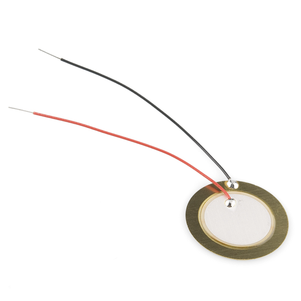
piezoelectric sensor
how the piezoelectric sensor works
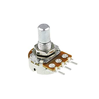
potentiometer sensor
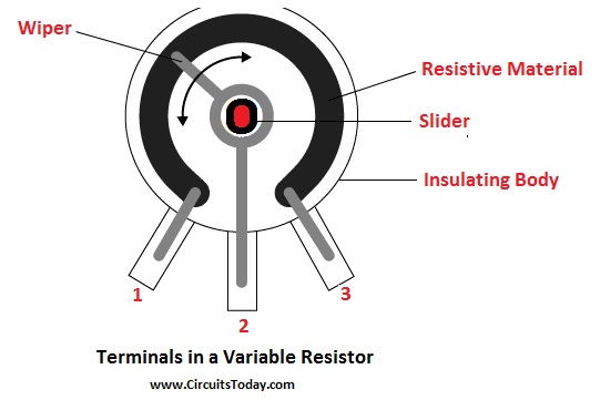
how potentiometer sensor works
- We are going to test the piezoelectric and potentiometer
- Resistor: 4.7 4.7K Ω
- Piezoelectric
- 5v from Arduino
- Potentiometer
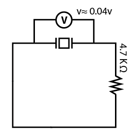
First test, and the diagram:
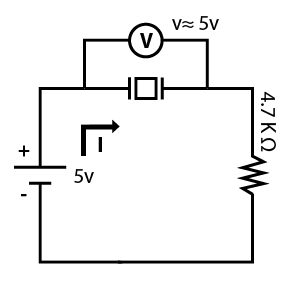
5v from arduino + Pizoelectric + resistor
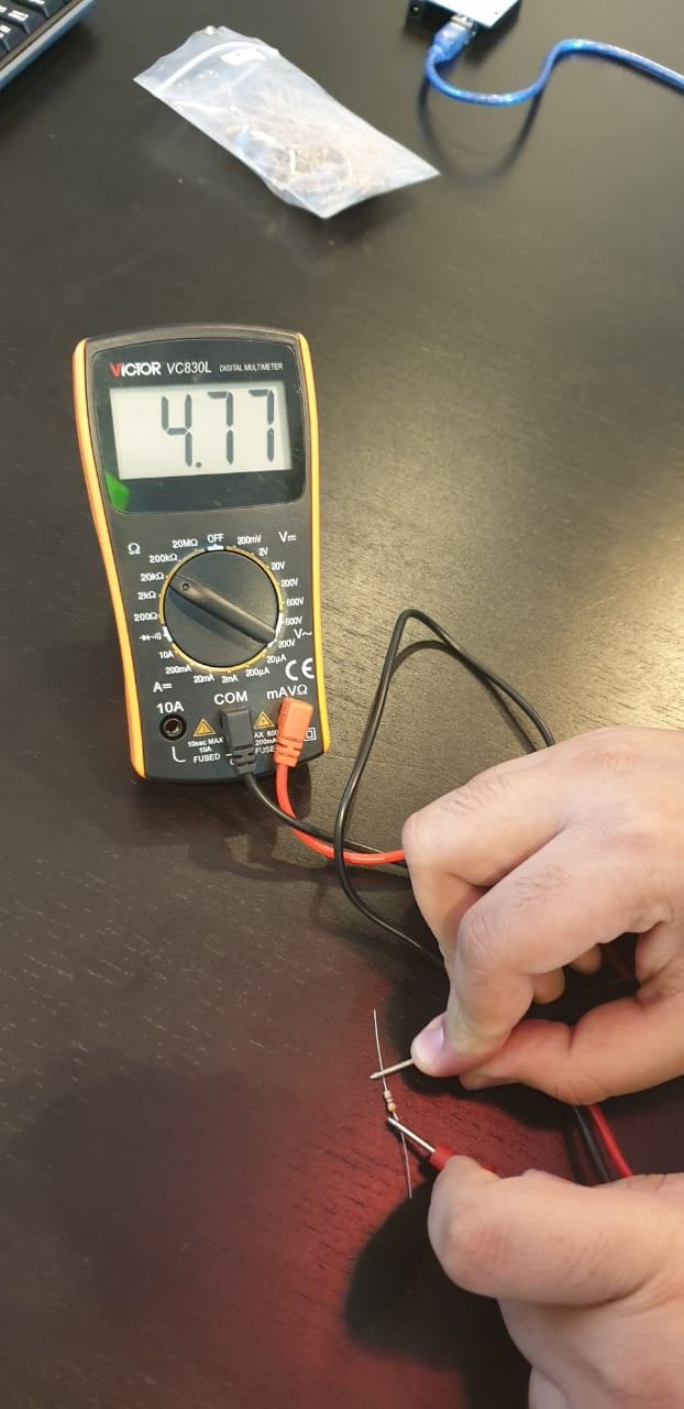
resistor value
5v from arduino + Pizoelectric + resistor
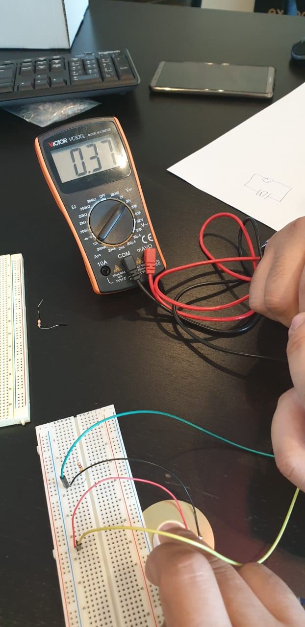
second test, and the diagram:
Pizoelectric + resistor
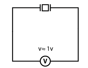
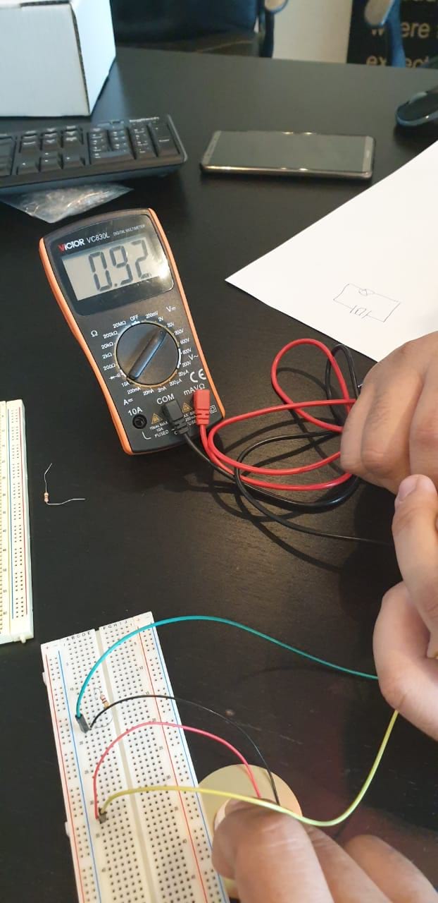
Third test, and the diagram:
Pizoelectric + resistor
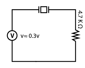
Fourth test, and the diagram:
Pizoelectric
Fifth test, and the diagram:
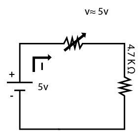
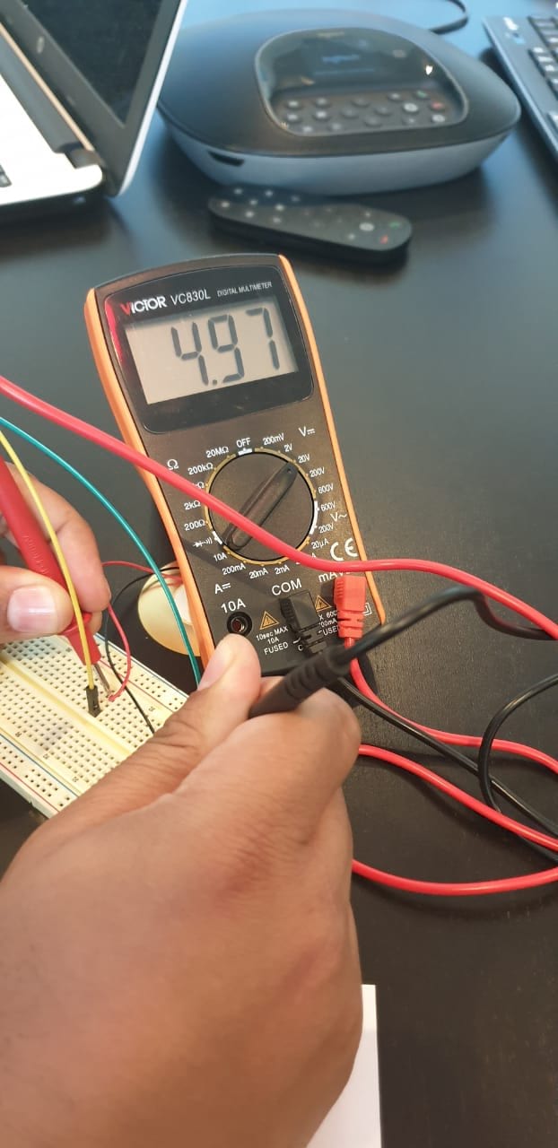
5v from arduino + Potentiometer + resistor
As we turning the potentiometer of right >> the voltage will change accordingly v ≈ 0 to 4.5v
Individual assignment
Sensors to micorocontroller board
This week, we will measure something by adding a sensor to a microcontroller board that you have designed and read it.
The microcontroller board that I have made was based on Attiny44 IC. I read more and more about the board and the behaviour. I used to connect the 6 header pins to the Arduino to program the board, so the Arduino will act as ISP (programmer) that means my microcontroller board will be receiving the code through the Arduino. And then I can easily disconnect the 6 wires and power the board using FTDI cable. In this case, I can program the pins that used to receive the code a moment ago. Because the pins will be occupied during code uploading only. The pins are:
Attiny44 Pins during uploading the code |
Attiny44 Pins during using FTDI |
1 (VCC) |
1 (VCC) … I can get 5 volts |
14 (GND) |
14 (GND) … I can get ground |
4 (Reset) |
4 (Reset) |
7 (MOSI) |
7 (MOSI) … It can be used as input or output |
8 (MISO) |
8 (MISO) … It can be used as input or output |
9 (SCK) |
9 (SCK) … It can be used as input or output |
I started programming the potentiometer. I should read the analog value as the knob turning. The voltage will be between 0 and 5 volts. The values that I will get between 0 to 1023 as it’s 10 bits (up to 2^10 in decimal) . So the first step here is to prepare the code and upload it using Arduino. I will use the pin 6 in the Attiny as an input to receive the signal from the potentiometer which is pin number 7 in the board. I will use the LED that soldered on board to make the indication as well. So now the code is:
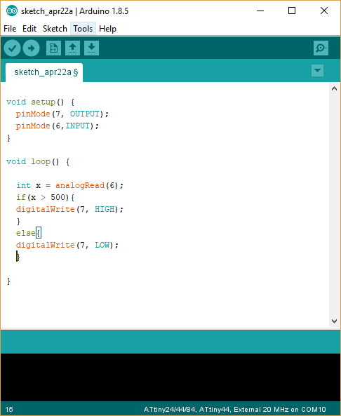
In the void setup function, I identified two main devices that will be connected and controlled by the board. LED which is an output connected to pin 7 and Potentiometer which is an input connected to pin 6. These pins are called 6 and 7 but physically they are not pin number 6 and 7, so I have to check the Attiny pin diagram always.
As for the void loop, I’m going to read the signal continually to check if someone is turning the potentiometer knob or not. I will control the LED based on the value that I’m getting from the potentiometer. As I described above, the values I’m getting will be between 0 and 1023 as decimal. I will check the value if it’s more than 500 the LED will turn on, else the LED keeps off.
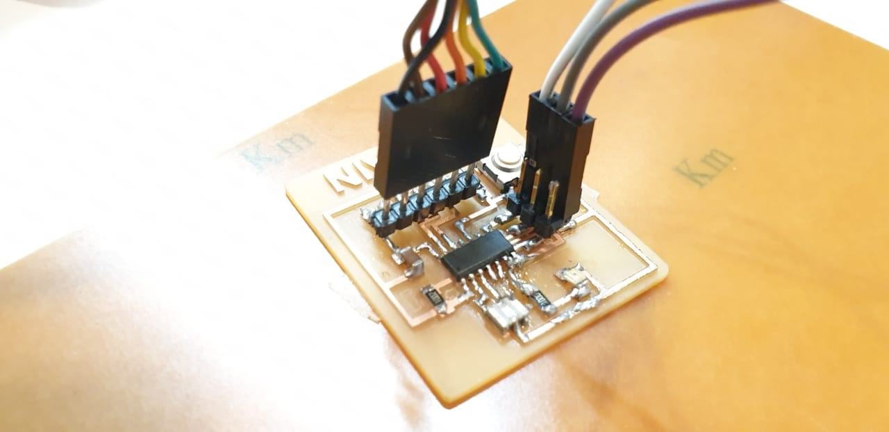
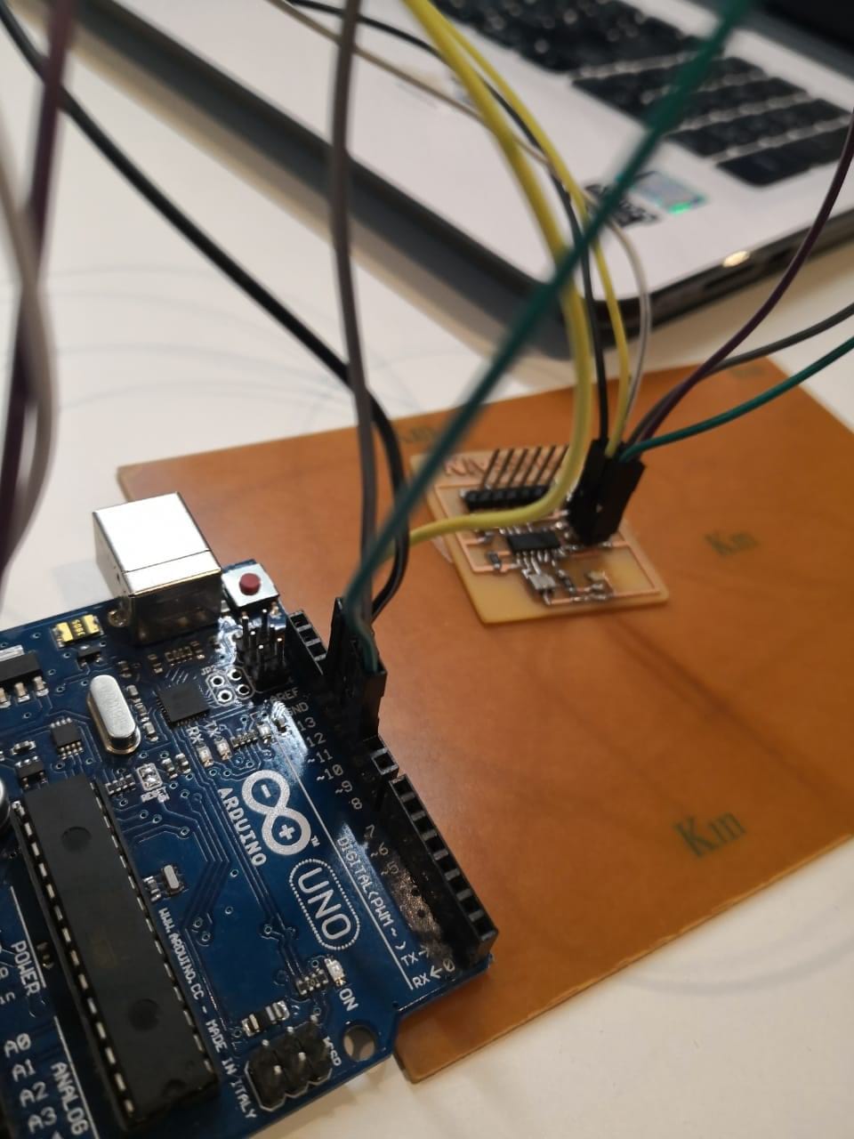
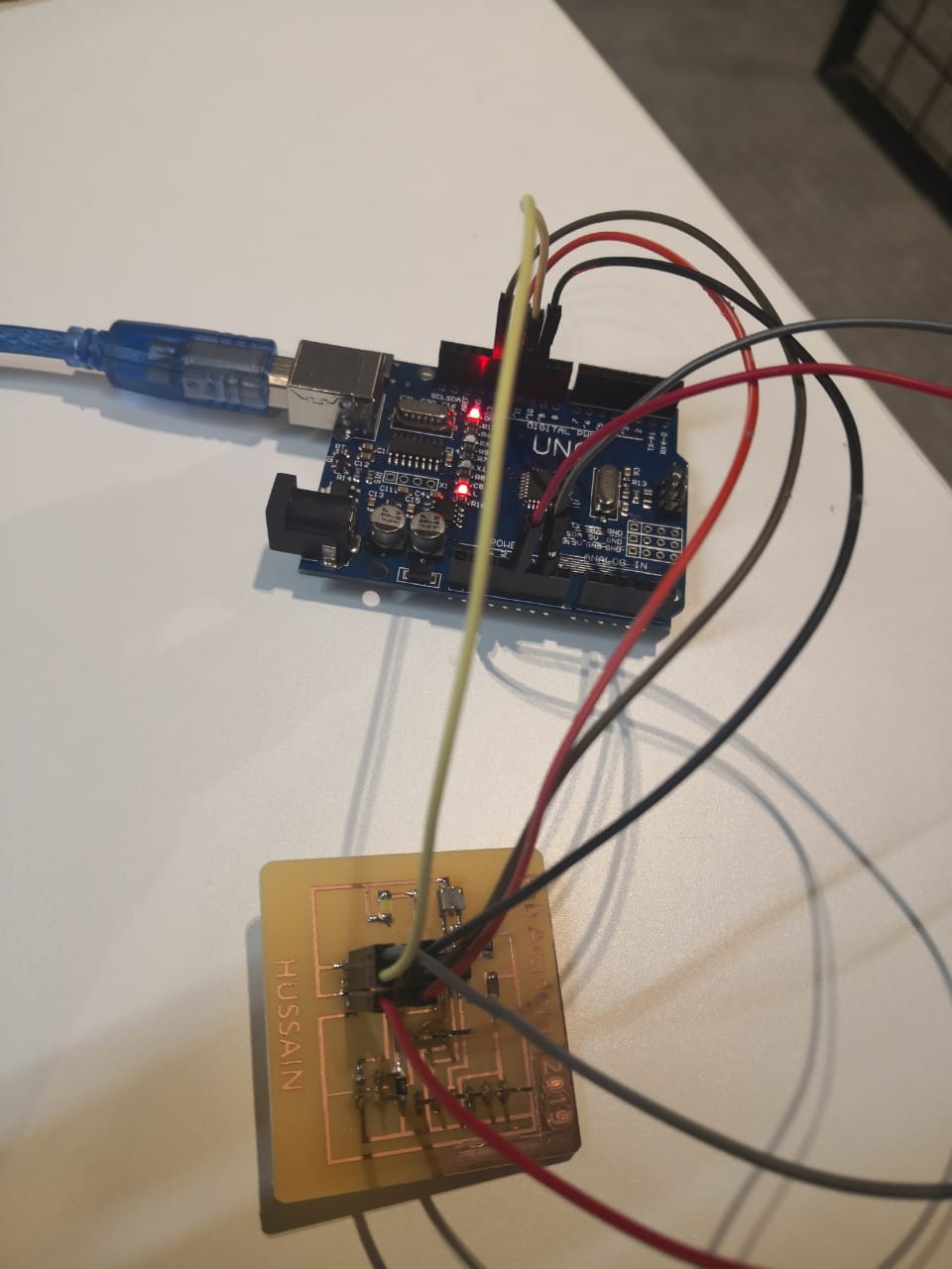
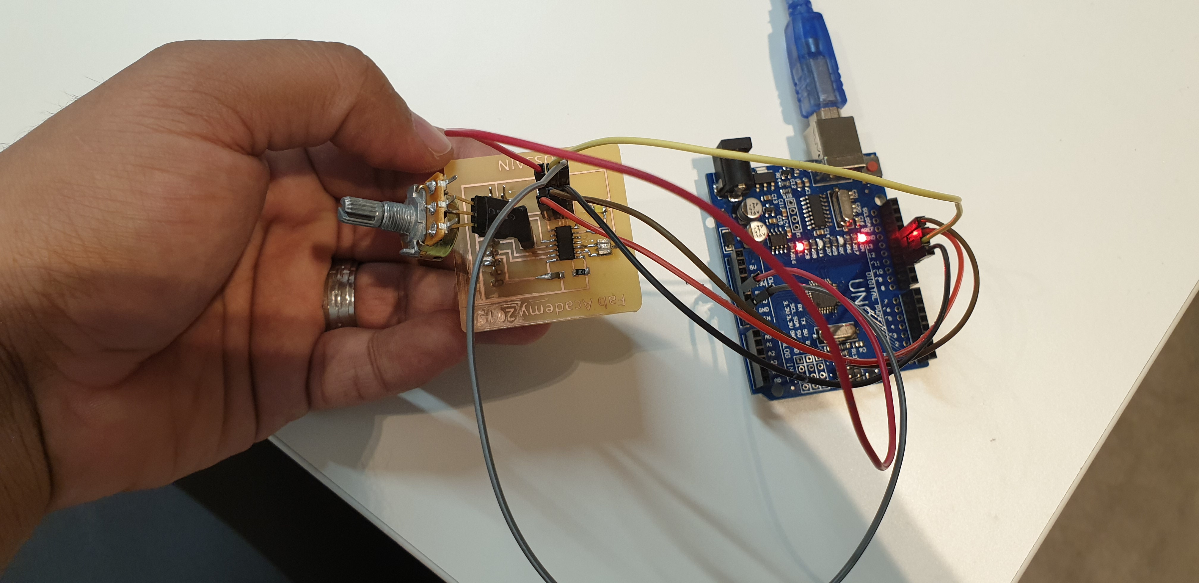
I’m going to transfer the programming to the Attiny board using Arduino, I will use the same steps that I did in Embedded programming week. I connected the Arduino to my Attiny board as the following:
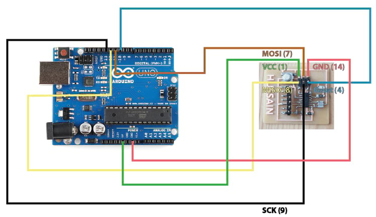
I connected the Arduino to the laptop using usb cable. I selected the board attiny44 and external 20 MHz crystal and Arduino as ISP. I uploaded the code that I have prepared and explained above.
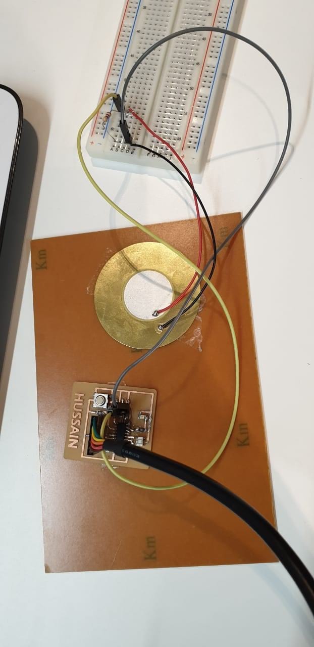
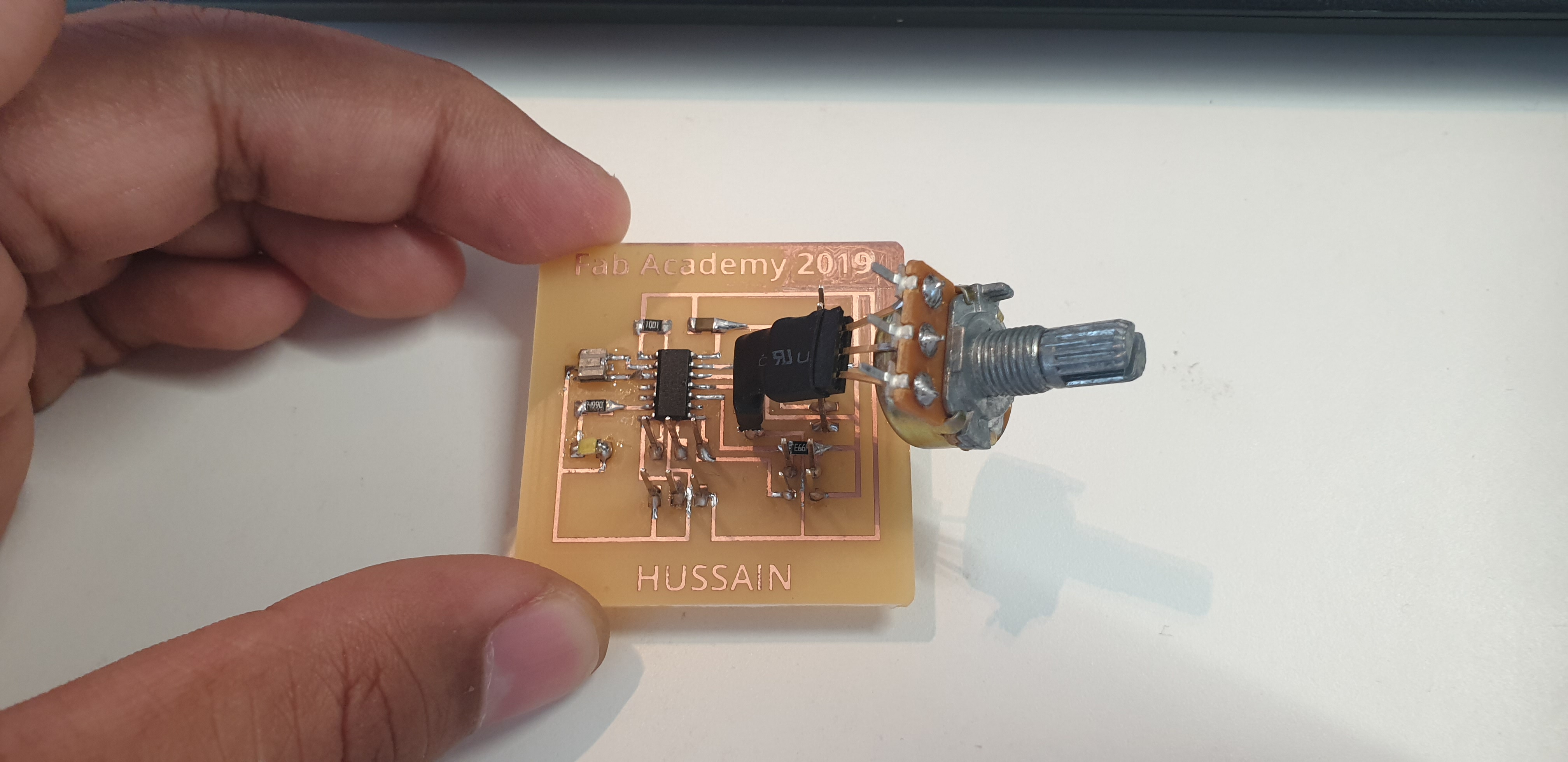
I disconnected the arduino and the wires between arduino and my board. Now no wires are connected to my board at all. The reason that I’m doing this because I used the same pins that were used during uploading the code. I connected the potentiometer with fixed resistor in series to make sure that the resistance will not be zero at some point so a huge current will return to my board
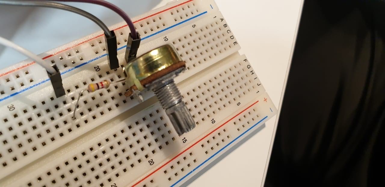
As shown above, I connected 3 pins between my board and the additional sensor (potentiometer + fixed resistor) the first one is 5 volts, the second one is GND, and the third one is input signal (ADC 6) . I connected the FTDI cable to the board as well
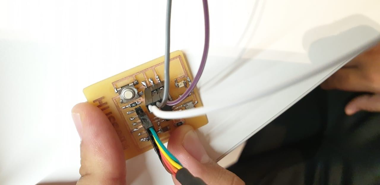
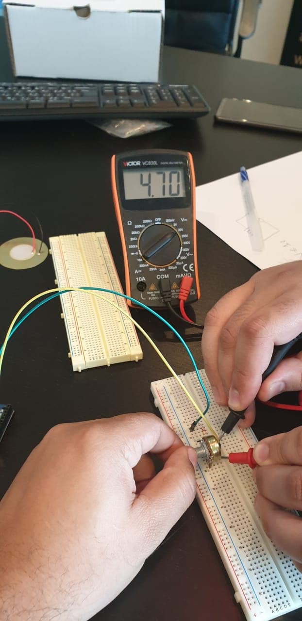
Now, I connected the usb (FTDI) to the laptop to power the circuit and started turning the potentiometer knob. I noticed that the LED tuning on and off as I’m doing that. So I get the multimeter to make sure that the code is doing the right thing as programmed.
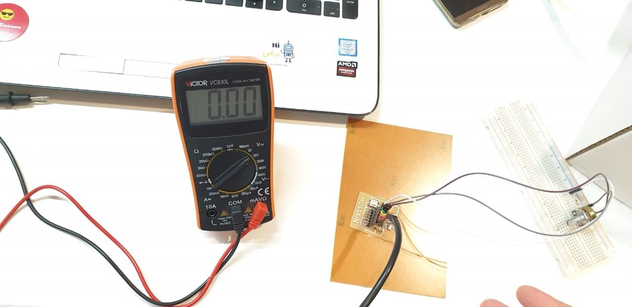
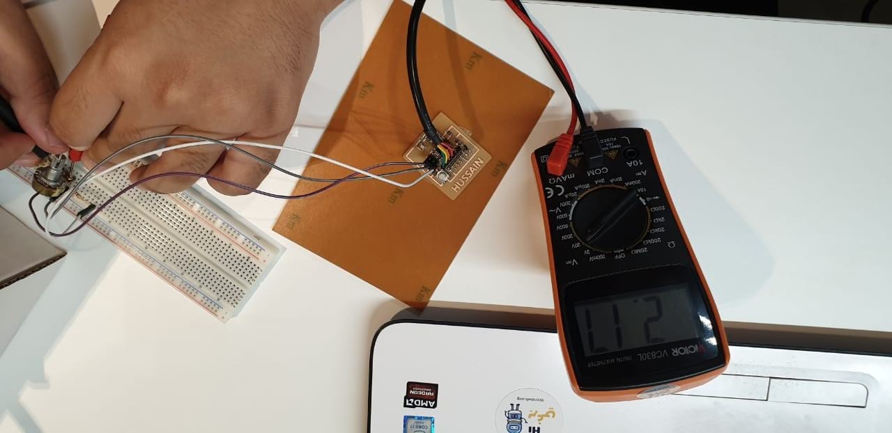
I setted the multimeter to measure the voltage that going to the board form potentiometer. I used the multimeter red wire and connected it to the potentiometer pin (the same point that connected to the Attiny board pin. And the black one connected to the GND because the signal is measured with respect to the ground.
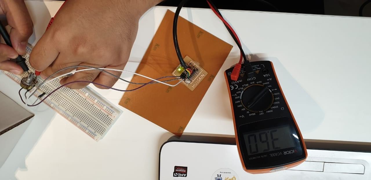
The LED is on while the voltage is more than 2.5 volts approximately. As I expected exactly, because I made the condition based on the value of 500 so if I mapped the values (0 - 1023) to (0-5 volts) the 500 is approximately 2.5 volts.
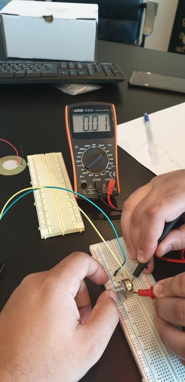
The LED is off while the voltage less than 2.5 volts. I recorded video showing the process
The second Sensor that I tested this week is piezoelectric element. As I described and did with potentiometer, I did the same thing here starting with preparing the code that I’m going to upload and then upload it using Arduino. Finally disconnect the arduino and connect the circuit to the board powering the board using FTDI cable.
Starting with the code, I did the following code:
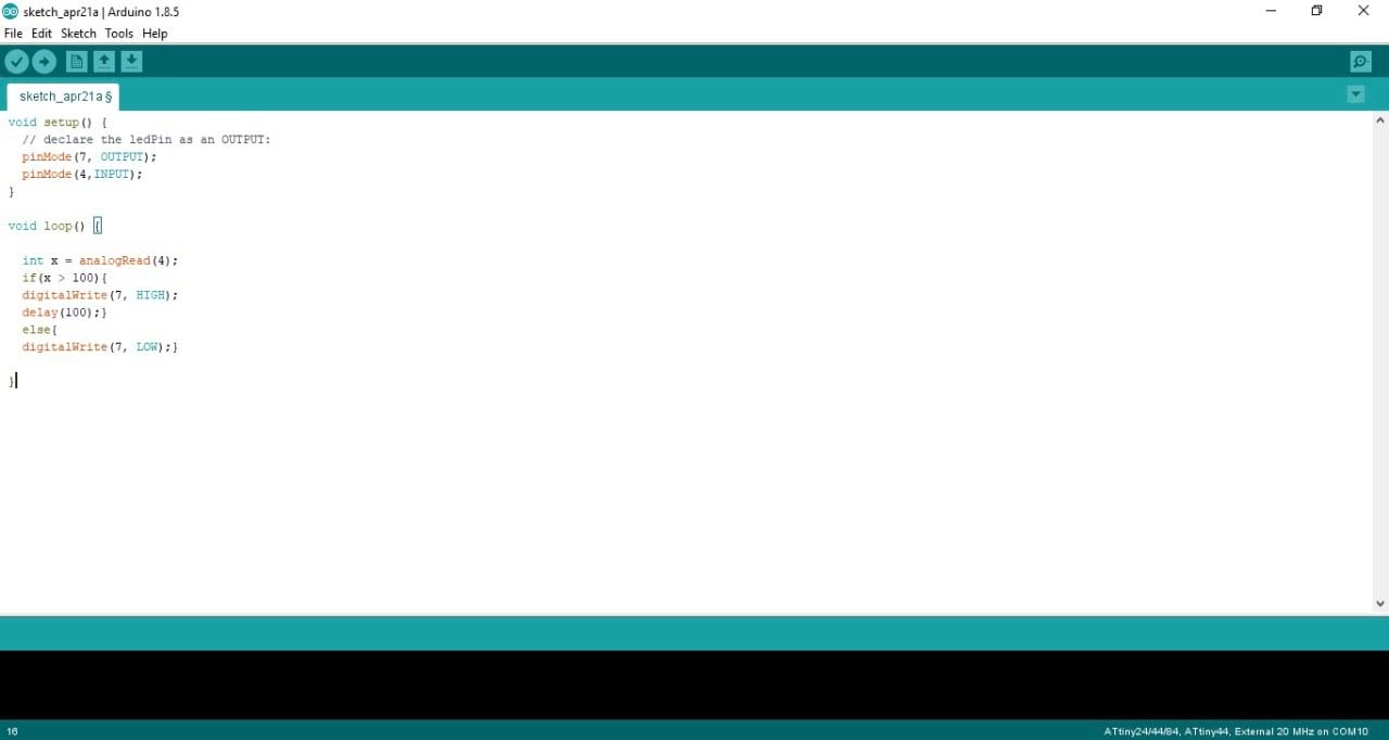
In this code I’m trying different pin to make sure that I can use different ones. I started the code defining the input and output, I planned to use the LED as an indication. So, the output is pin 7 (LED), and the input is pin 4 (piezoelectric).
Then and as I’m going to read analog values as knocking the piezoelectric. I added variable to save the piezoelectric reading, and then comparing the value with 100 if the value is greater than 100, the LED will turn on for 100 ms because if I didn’t use the delay I will never notice the LED while is on. If the value is less than 100, the LED is off.
I connected the board to the Arduino to transfer the code and program the Attiny44 microcontroller
Then I uploaded the code as I did in the embedded programming week and above. Disconnecting the Arduino and started connected the circuit and FTDI cable to power the board up. As for the circuit needed to connect piezoelectric, I used resistor connected in parallel with piezoelectric to protect the Attiny44. And connecting one of them to pin 4 and the other one with GND. As the piezoelectric generates voltage while knocking.
After powering up the circuit, I started knocking the piezoelectric to see what is happening. And this is really cool, what happened is the same what I expected.
To open or download file
Programing File of potentiometer: Click Here!
Programing File of piezoelectric: Click Here!
___________________________________________________________________________________________________
Custom Board according to Inputs that I have
List of components:
Part |
Value |
Package |
Library |
BUZZER |
|
02P |
con-amp-quick |
C1 |
|
C1206 |
resistor |
IC1 |
ATTINY44-SSU |
SOIC14 |
fab |
J1 |
|
1X06-SMD_RA_MALE |
SparkFun-Connectors |
PIEZO |
|
02P |
con-amp-quick |
POTENTIOMETER |
|
03P |
con-amp-quick |
R1 |
|
R1206 |
resistor |
R2 |
|
R1206 |
resistor |
R3 |
|
R1206 |
resistor |
U$1 |
LED |
LED1206 |
fab |
U$2 |
RESONATOR |
EFOBM |
fab |
U$4 |
AVRISPSMD |
2X03SMD |
fab |
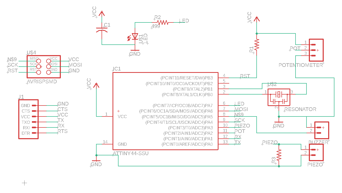
The schematic
the board
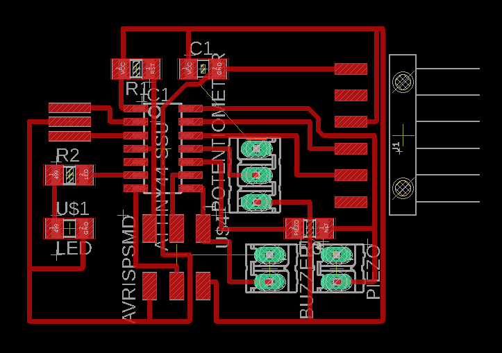

Trace Layout
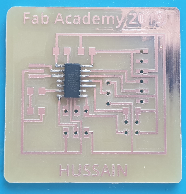
Soldring the ATtiny 44
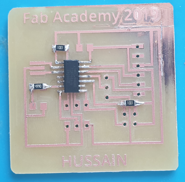
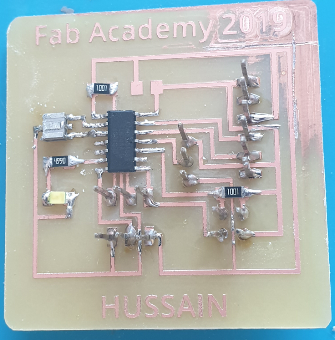
All the components
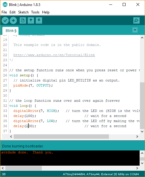
Burn the bootloader
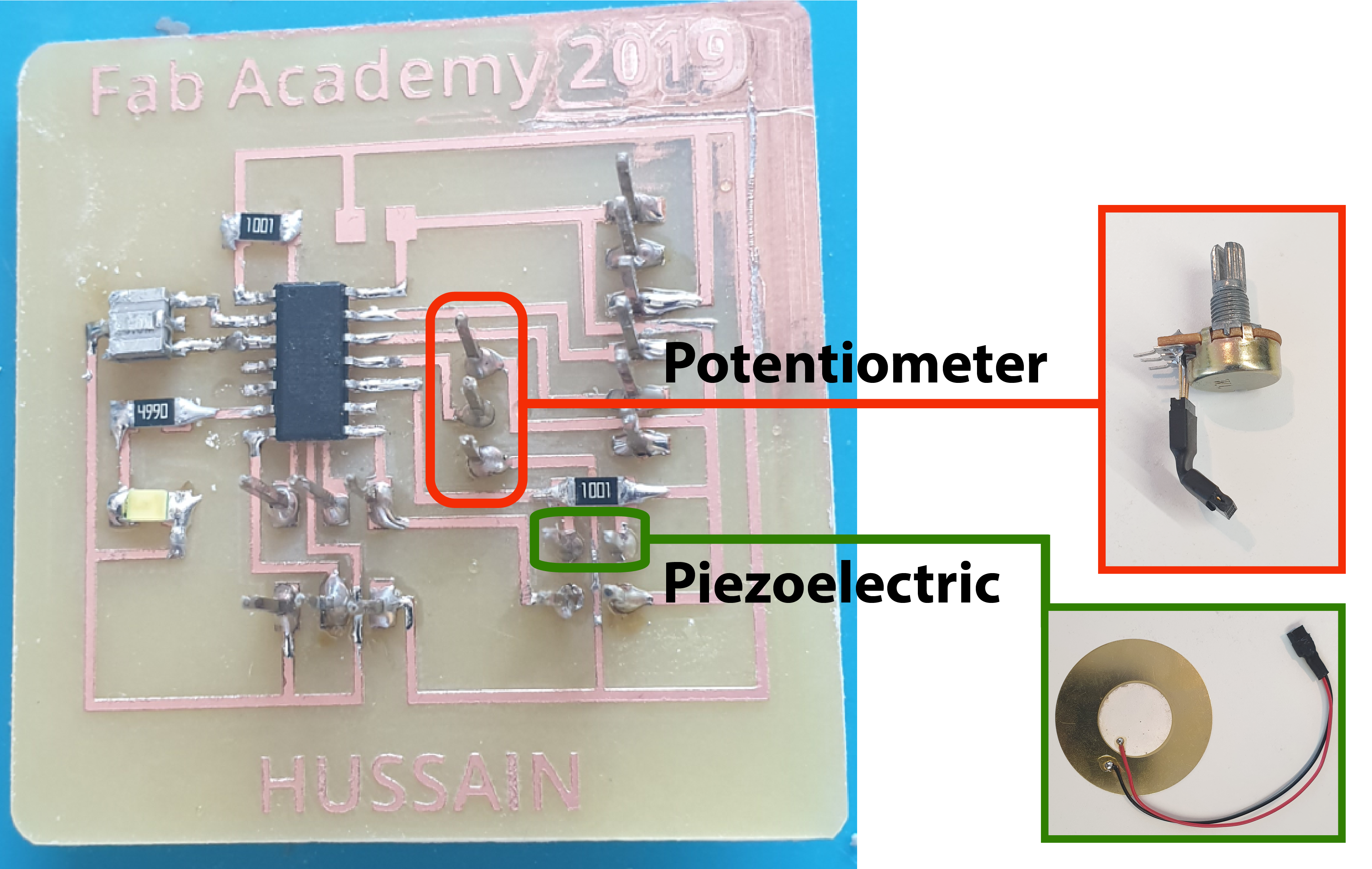
where the sensors conected
Potentiometer sensor
Piezoelectric sensor
Code and test the sensor
Piezoelectric sensor
Code and test the sensor
To open or download file
Programing File of potentiometer: Click Here!
Programing File of piezoelectric: Click Here!