Output Device
Assignment : Add an output device to a microcontroller board you've designed and program it to do something
Work
For This Assignment first I use my Hello Board produced in the Electronic Production Week, and I use Arduino Ide for program It. The first sketch i do, I use as output a piezo and I connect it on a PWM PIN.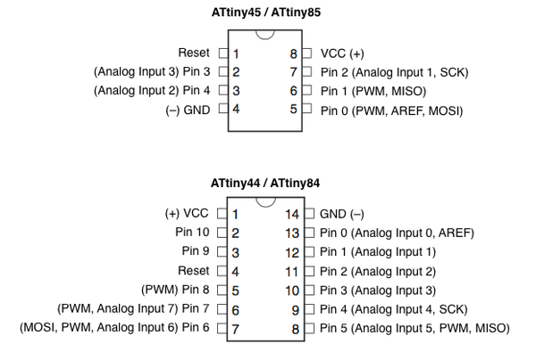
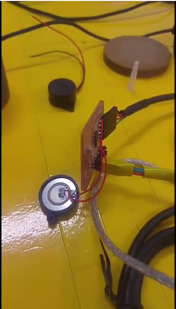 Here you can see the video of the sketch:
Tone Melody Attiny44 - Piezo
#define  c     3830    // 261 Hz
#define  d     3400    // 294 Hz
#define  e     3038    // 329 Hz
#define  f     2864    // 349 Hz
#define  g     2550    // 392 Hz
#define  a     2272    // 440 Hz
#define  b     2028    // 493 Hz
#define  C     1912    // 523 Hz
#define  R     0


int speakerOut = 8;
int DEBUG = 1;

void setup() {
pinMode(speakerOut, OUTPUT);

}


int melody[] = {  C,  b,  g,  C,  b,   e,  R,  C,  c,  g, a, C };
int beats[]  = { 16, 16, 16,  8,  8,  16, 32, 16, 16, 16, 8, 8 };
int MAX_COUNT = sizeof(melody) / 2; // Melody length, for looping.

// Set overall tempo
long tempo = 10000;
// Set length of pause between notes
int pause = 1000;
// Loop variable to increase Rest length
int rest_count = 100;

int tone_ = 0;
int beat = 0;
long duration  = 0;


void playTone() {
long elapsed_time = 0;
if (tone_ > 0) { // if this isn't a Rest beat, while the tone has
  //  played less long than 'duration', pulse speaker HIGH and LOW
  while (elapsed_time < duration) {

    digitalWrite(speakerOut,HIGH);
    delayMicroseconds(tone_ / 2);

    // DOWN
    digitalWrite(speakerOut, LOW);
    delayMicroseconds(tone_ / 2);

    // Keep track of how long we pulsed
    elapsed_time += (tone_);
  }
}
else { // Rest beat; loop times delay
  for (int j = 0; j < rest_count; j++) { // See NOTE on rest_count
    delayMicroseconds(duration);
  }
}
}

void loop() {
// Set up a counter to pull from melody[] and beats[]
for (int i=0; i
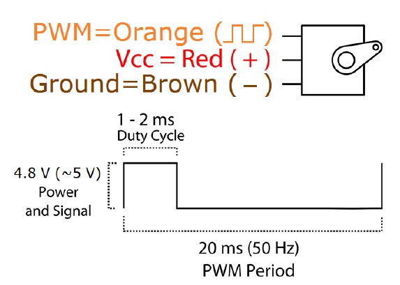
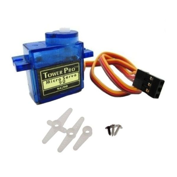
After this Test I try to understand How I can Program a servo and a Stepper Motor, because I need to use them in the Machine Disign Assignment. I first use Arduino and a bradboard, and I create a small cirtuit first with the servo, and after with the stepper motor. The Servo I use is the SG90.
This is th Cirtuit:
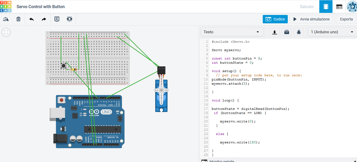
Simulation with Thinkercad
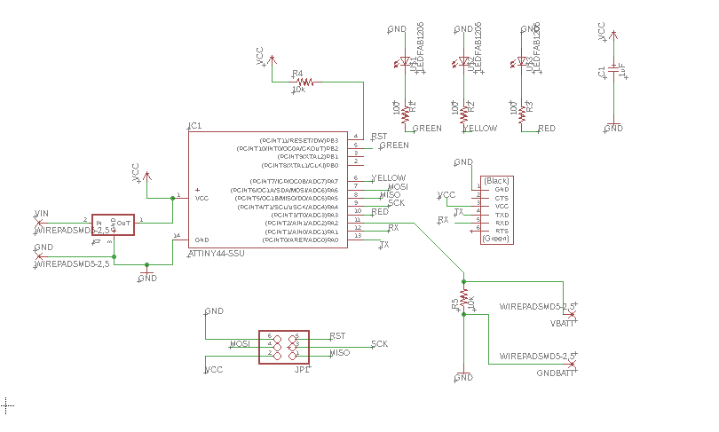
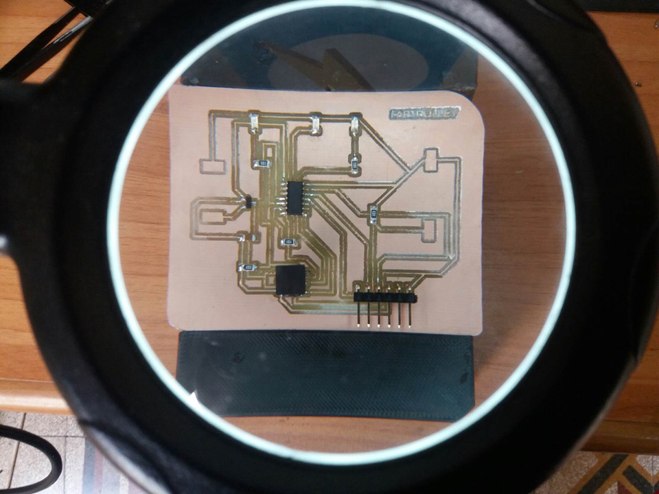
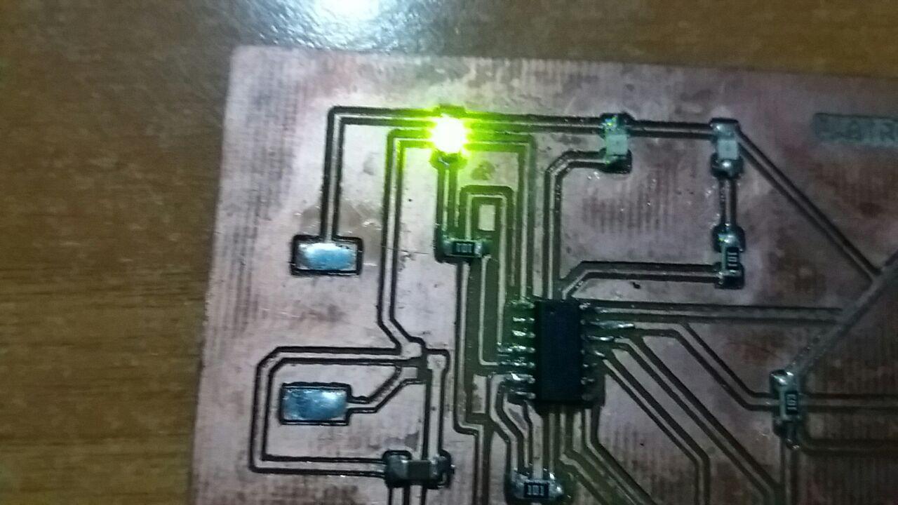
With the board built for my Final Project I made a small sketch to test the LEDs on the board.
You can find all the information on how I designed and created this board on the Final Project page.
Download ZONE
- Servo_control_with_button
- Servo_control_with_button - Thinkercad schematic
- Tone Melody Piezo
- Blink with FabTrolley board
- Blink Hex File
- Back To: Home
- Date: 26th April
- Topic: Output Device