Week eleven: Input devices
Individual assignment
For this week, we had to design and fabricate a electronic board using a input device for our final project.
Our devices
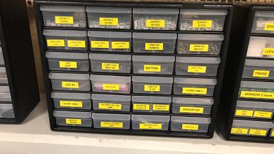
We have several input devices in our laboratory

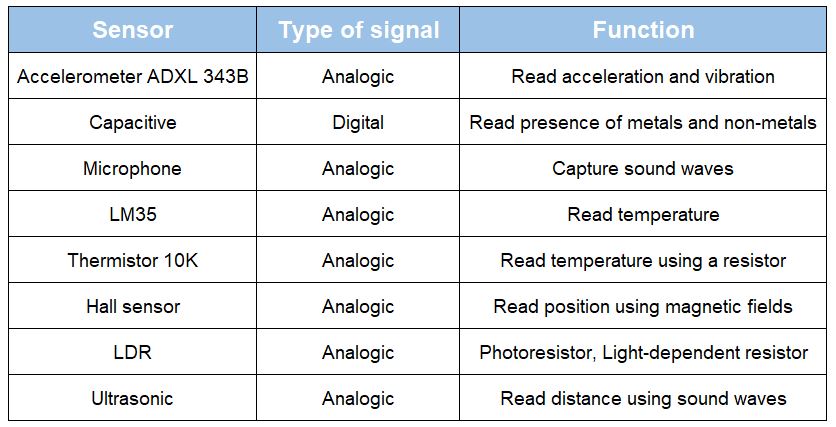
I decided to use accelerometer sensor ADXL-343B, because in my final project i want to use a bracelet to control the direction of the boat instead of a steering wheel.
Reading the datasheet i realized that this sensor works with 2.0V to 3.6V , so i needed a 3.3v regulator in my board Look the datasheet here .This time i decided to use an Attiny45 like Neil's Exampe.
This time i decided to use an Attiny45 like Neil's Exampe. This microcontroller has his own oscillator, so i didn't use a external. Look the datasheet here
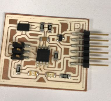
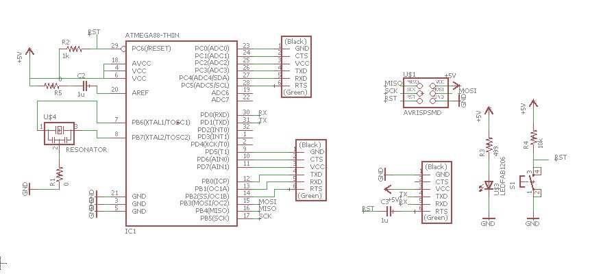
With this information i started to design the schematic board
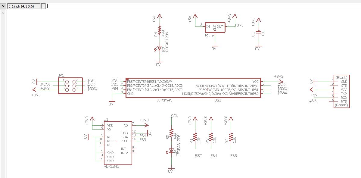
As you can see, i put a 3.3V regulator, 1 power LED, and 1 LED as output for attiny 45.
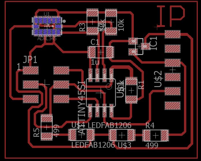
And fabricate using Roland MDX as always
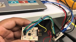
Once the board is finished, i used my ISP board from electronic's production week to burn bootloader, it works with the second board i fabricated
Configurate ports and devices
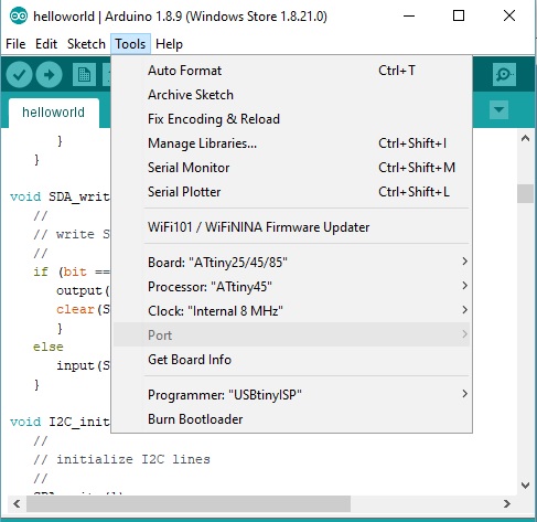
Done burning bootloader
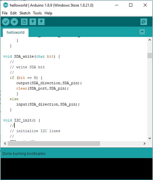
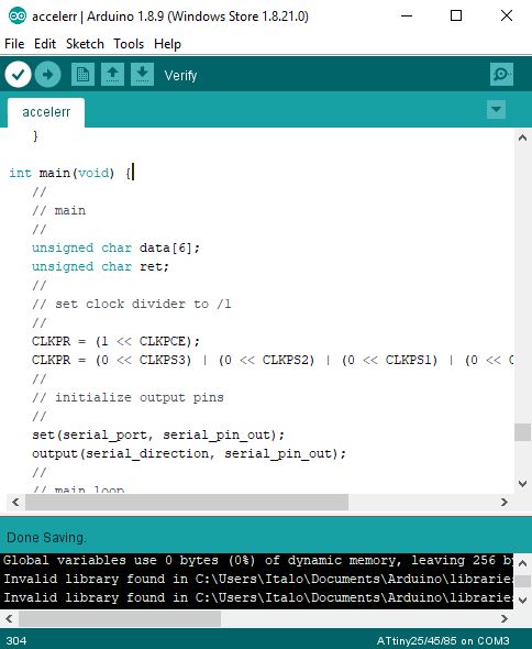
Once the attiny 45 could be programmed i used Neil's "C" code to check if the program can be uploaded to the attiny
Coonected my board with FTDI
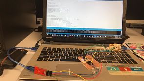
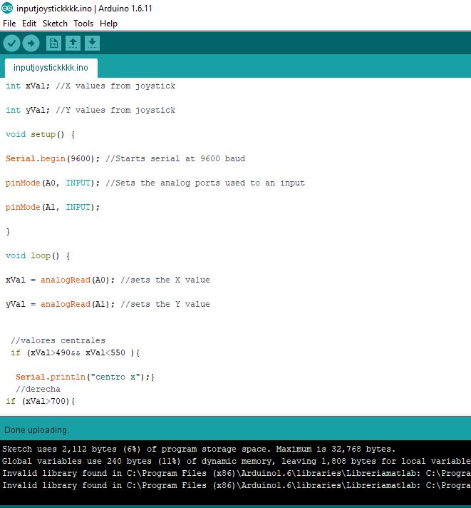
The program was uploaded!
UPDATE
I decided to change the input device of my final project, instead of an accelerometer I preferred to make a joystick
This is the joystick we have in our laboratory, as you can see has his own board
I would like to use this board for my final project, so I used an atmega 328p that is compatible with arduino libraries, in addition to having more memory than attiny
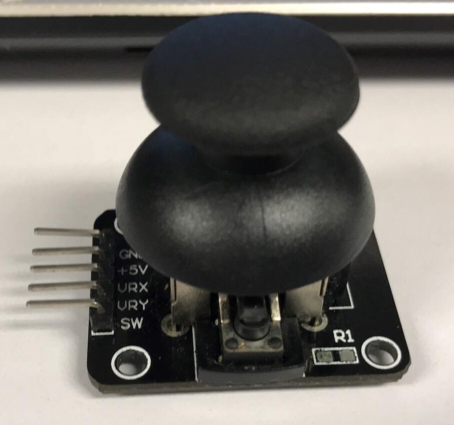
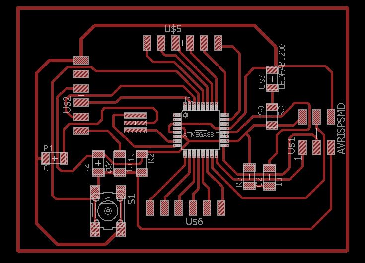
Thanks to the atmega, I have several analog pins that will serve me for the joystick, since this has 2 pins, one for the X axis and the Y axis, as I found on the internet the joystick is based on 2 potentiometers, so at the moment of program I will take into account the values of a normal potentiometer, to design the board I used a 3x2 pinheader to burn the bootloader of the microcontroller, a 20Mhz oscillator, a reset button, some resistors 0 to be able to skip the tracks, a led to indicate that the plate is energized and capacitors to filter the noise
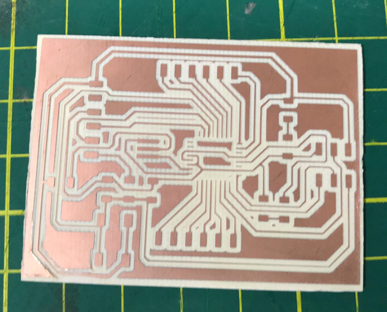
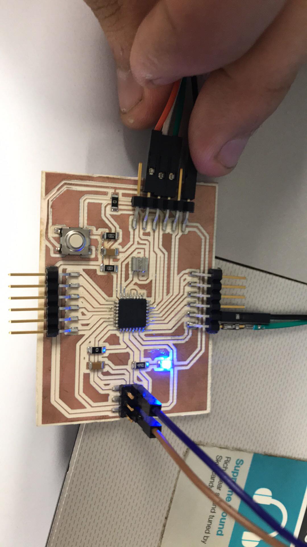
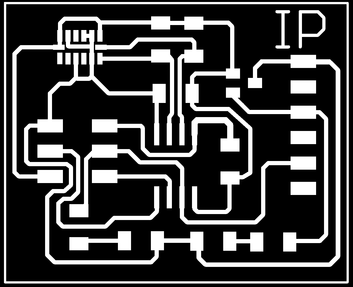
This would be my plate after several attempts
Outline

I exported my board as png and used fab modules to perform CAM, as in the week of electronic design, I use 0.1 of diameter of milling cutter, for this reason I can pass 2 tracks below the resistances
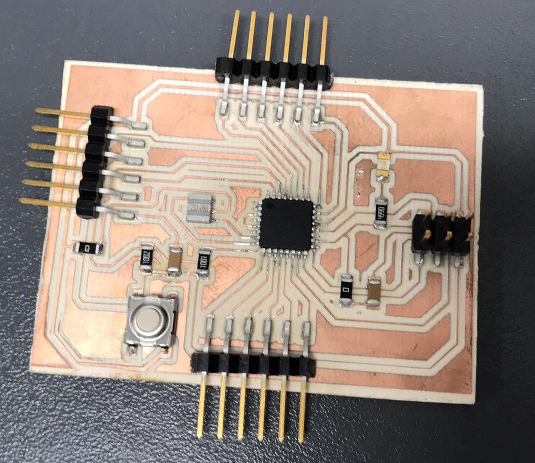
I soldered with flux and a heat gun as electronics production
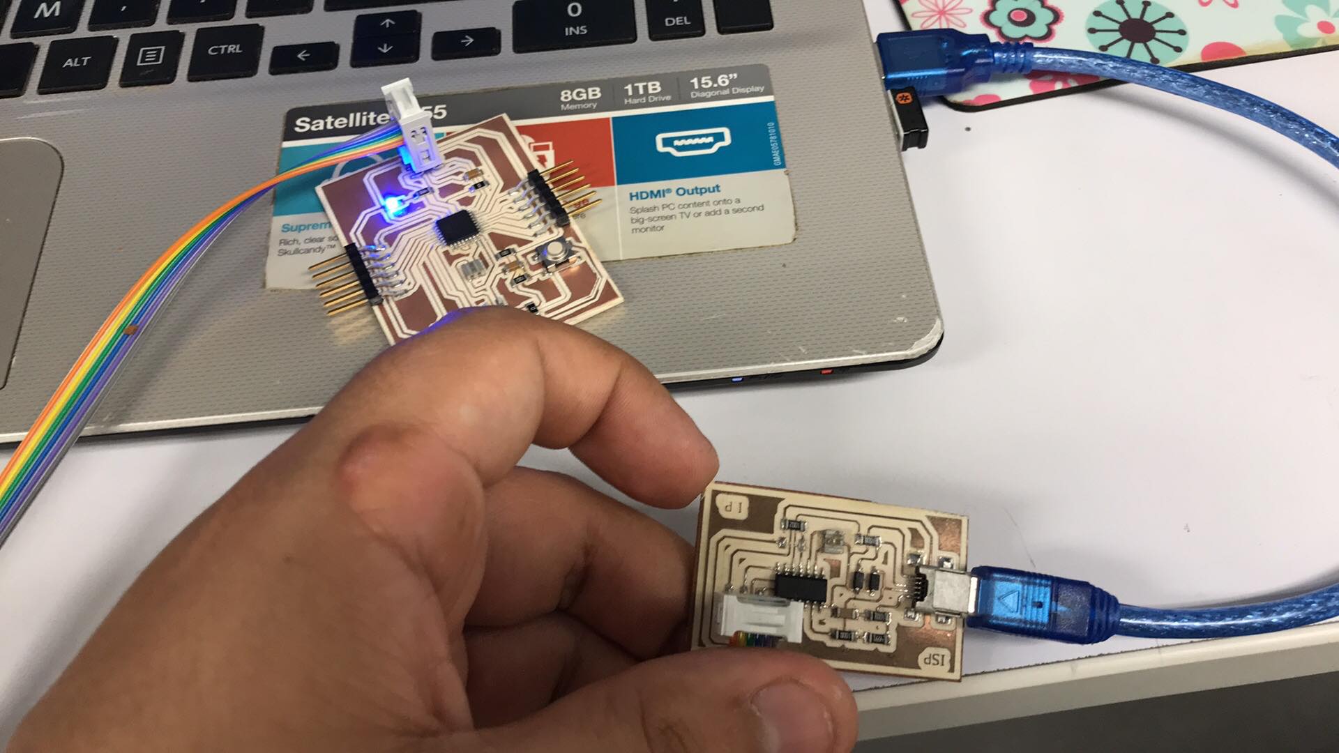
I connected with my ISP to burn bootloader
I soldered with flux and a heat gun as electronics production
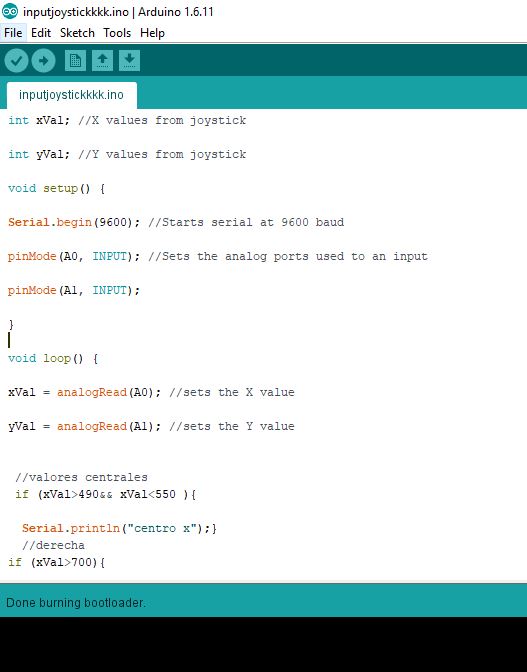
Once the bootloader is burned, I proceed to program, as I mentioned before the joystick acts as 2 potentiometers so I divided the values, if it is less than 400 on the x axis the program will interpret it as a left position, greater than 490 on the right x axis, in the axis and the same, then a message will be displayed on the serial monitor. To achieve this communication, I will use the FTDI that has the Tx and Rx pins characteristic of this protocol, it should be noted that I took this into account in the design of the board
int xVal; //X values from joystick
int yVal; //Y values from joystick
void setup() {
Serial.begin(9600); //Starts serial at 9600 baud
pinMode(A0, INPUT); //Sets the analog ports used to an input
pinMode(A1, INPUT);
}
void loop() {
xVal = analogRead(A0); //sets the X value
yVal = analogRead(A1); //sets the Y value
//valores centrales
if (xVal>490&& xVal<550 ){
Serial.println("centro x");}
//derecha
if (xVal>700){
Serial.println("derecha");}
//izquierda
if(xVal<490){
Serial.println("izquierda");}
//arriba
//valores centrales eje y
if (yVal>490&& yVal<550 ){
Serial.println("centro y");}
//derecha
if (yVal>700){
Serial.println("abajo");}
//abajo
if(yVal<490){
Serial.println("arriba");}
//arriba
delay(5000);
}
These are the connections I made, the FTDI to communicate the data captured by the joystick (analog signal), the X and Y axis of the joystick to pins A0 and A1 of the atmega, that is to say 25 and 26 and VCC and GND of the joystick to the plate
Downloads
Schematic BoardPNG board
Joystick SCH
Joystick BRD
Joystick code
To see the complete development of the group assignment visit the following link that corresponds to the CIT page