Week six: 3D Scanning and printing
Individual assignment
For this task, i designed 2 objects in SolidWorks that could not be made subtractively, a coil and a propeller. It means that it can't be machined by a CNC with 3 axis, both designs can't be machined because the mill can't pass between the curved surfaces and can't machine the part of the piece that is holded. One of the advantages of the additive technology is that can make complex designs, but take more time when create simple designs.
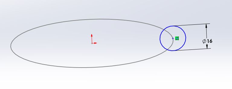
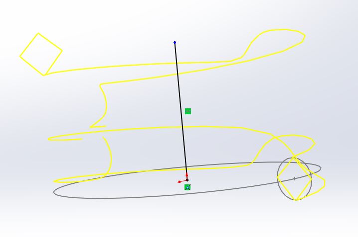
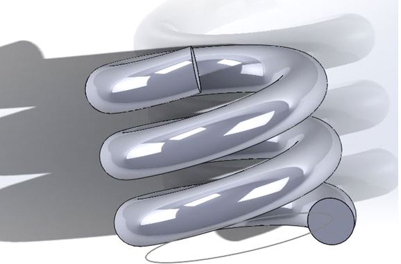
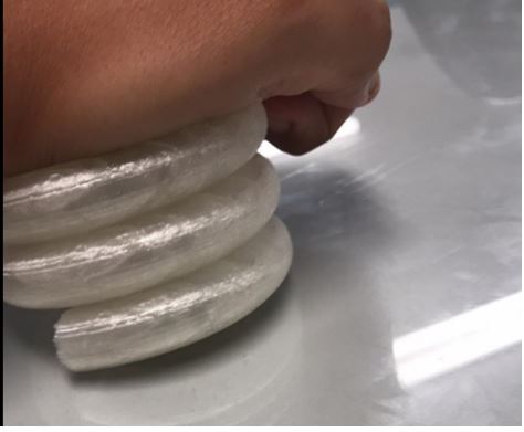
First, i designed a coil with 3 sketches, 2 circles and one line
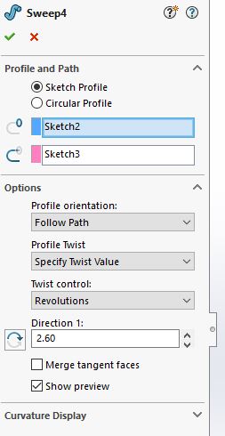
Then i use the command sweep 4
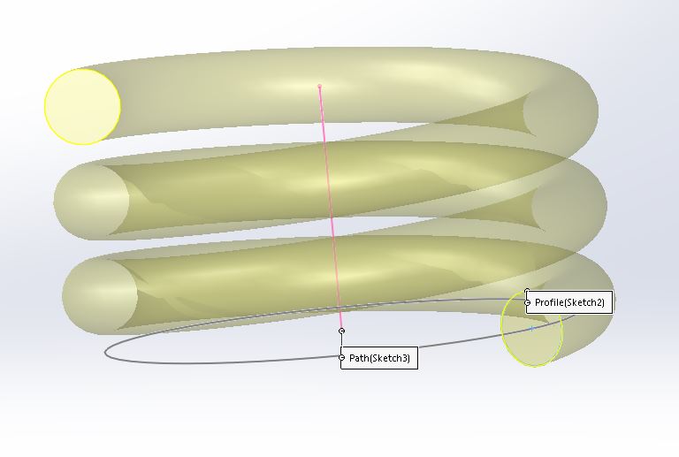
Coil result
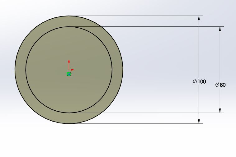
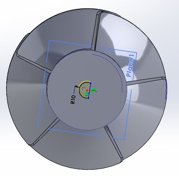
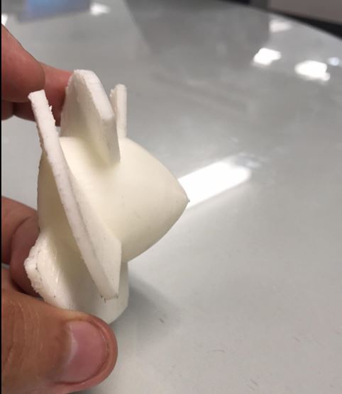
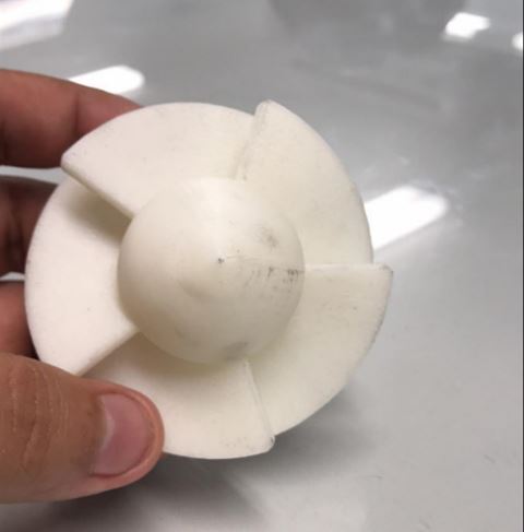
Thinking in my final project, i designed a propeller
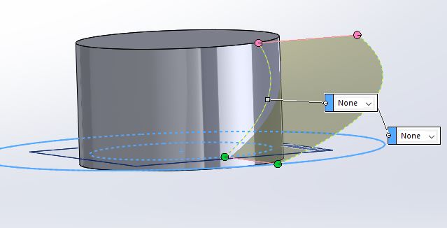
I made 2 circles with different diameter in the same sketch
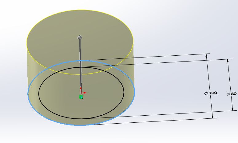
Command extrude
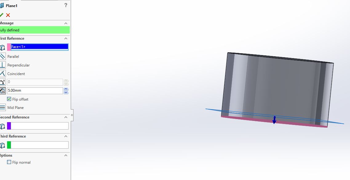
Parallel plane
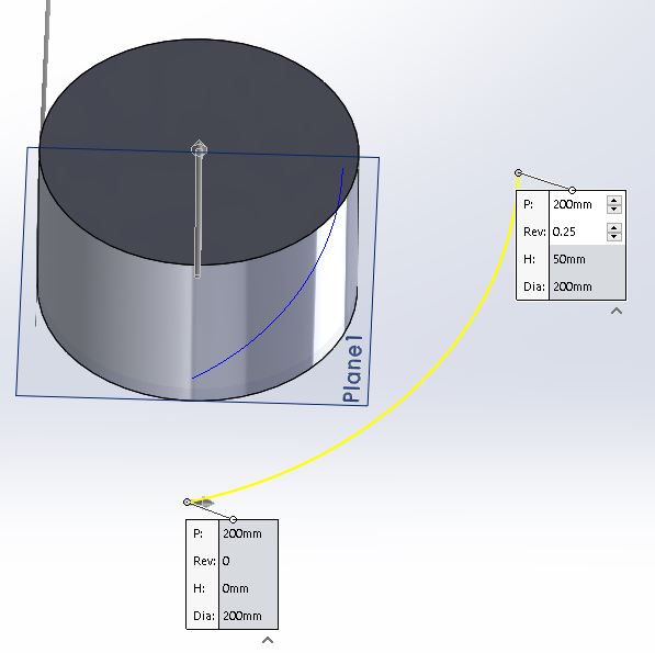
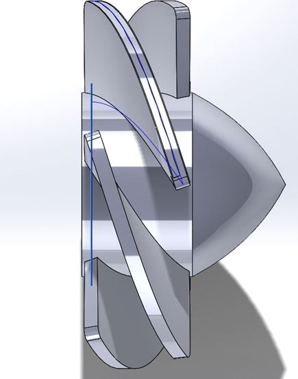
Command helix
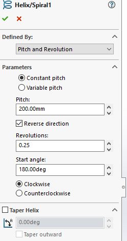
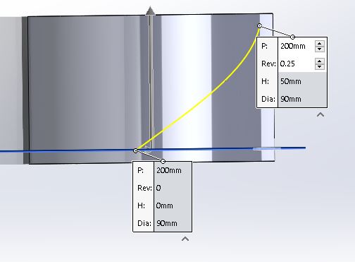
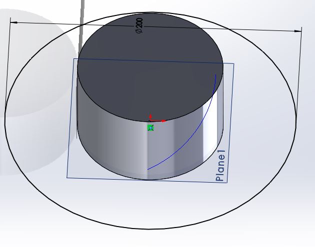
Command helix
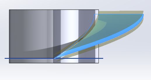
Command surface
Offset and fillet
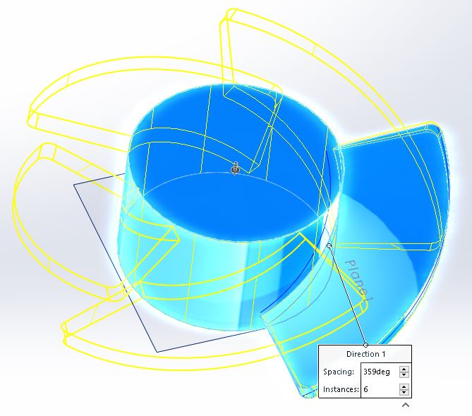
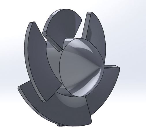
Circular pattern
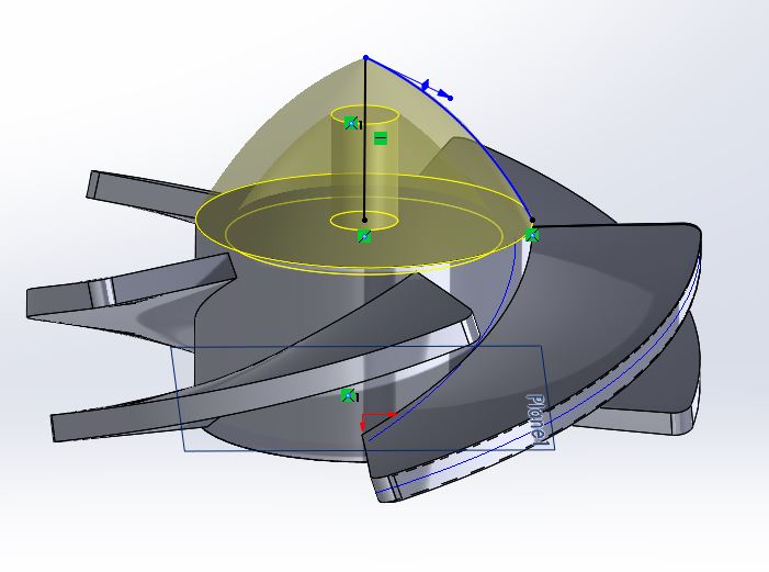
Revolution 360 degreed
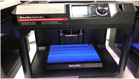
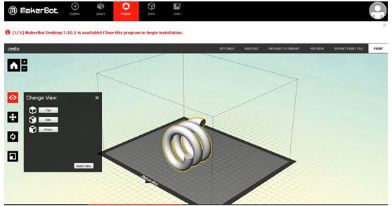
So, i exported the files in STL format to be recognizable by the printer, for the first object i used a Makerbot + printer, and PLA as filament.
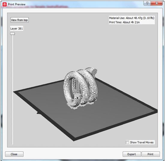
Opened STL files in Makerbot software, put in a correct position and change the parameters
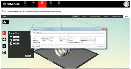
The temperature depends of the material, in this case i choose 230ºC for PLA
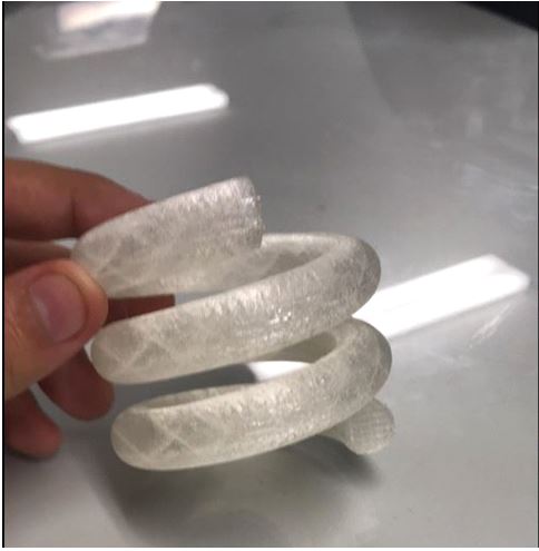
Final result!
For the propeller, i used a Makerbot 2X to print and ABS as filament, the process is the same.
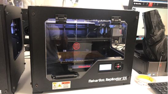
This is the result
3D Scanning
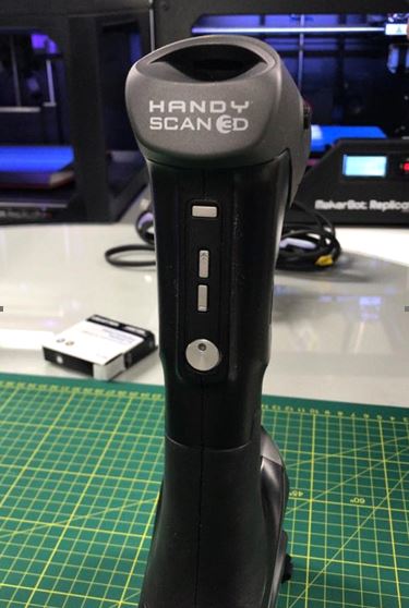
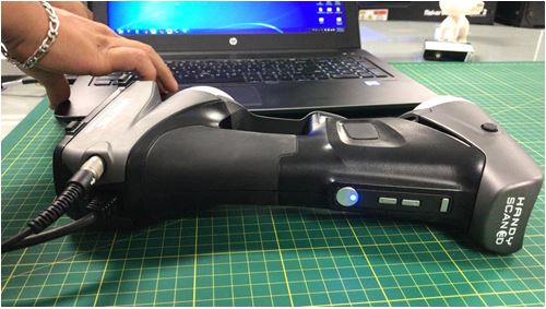
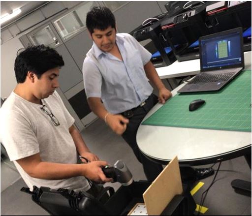
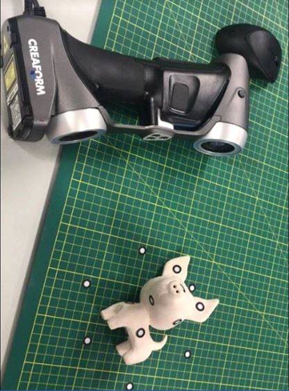
For this task, i used a handySCAN700. I followed these steps
Connect and turn on the scanner
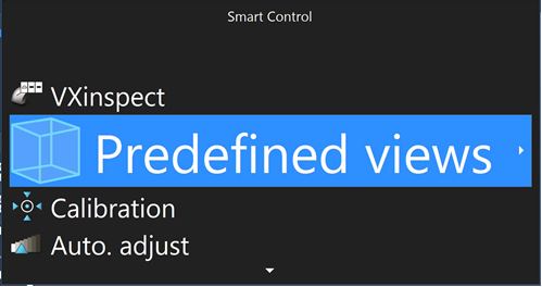
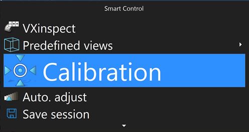
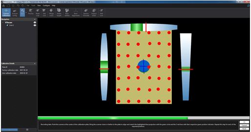
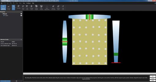
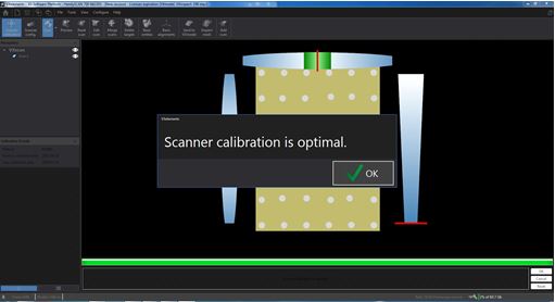
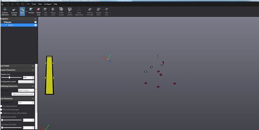
Click in VXscan and start the calibration

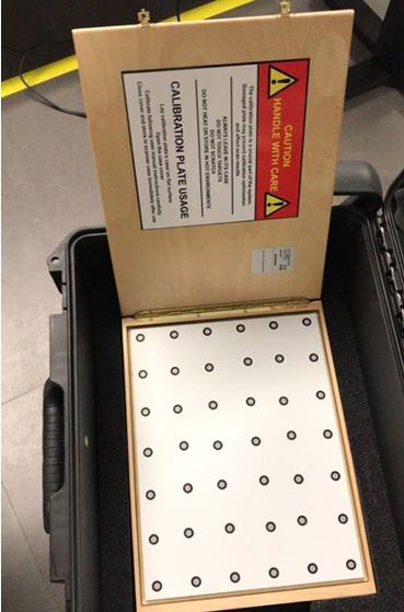
This is the template required to the calibration
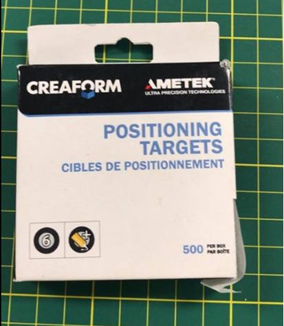
When the calibration is complete, put the targets in the table and the dog
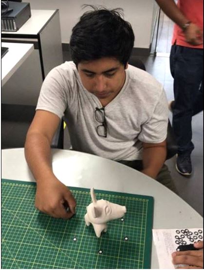
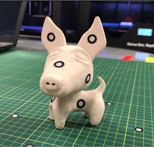
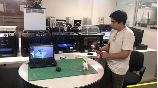
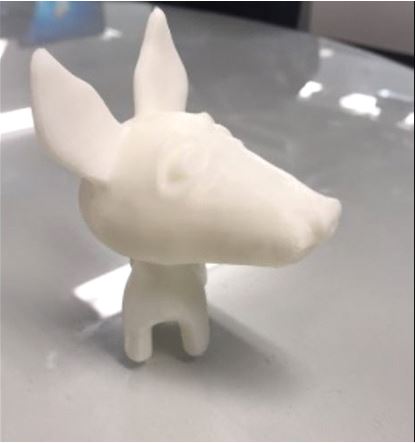
In this case i scanned a dog made of clay
Start scanning

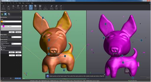
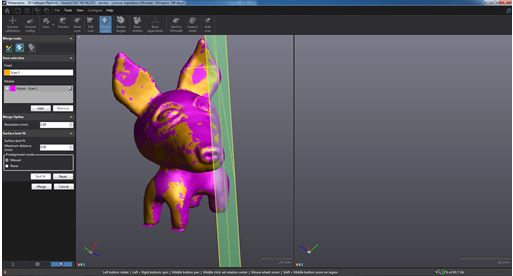
I needed to scan the object in several positions because the neck, ears and tail dont see so well.
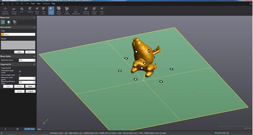
In the sotware we have to create some joints to guide de object, as you can see in the picture
Fusion both objects
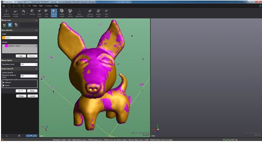
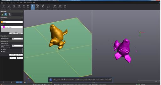
Scan one more time in another position
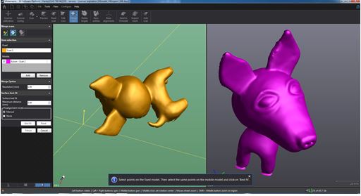
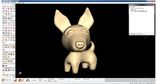
Then, i exported the model in OBJ format to Freeform software and use the tool smooth to correct imperfections in the coil and neck
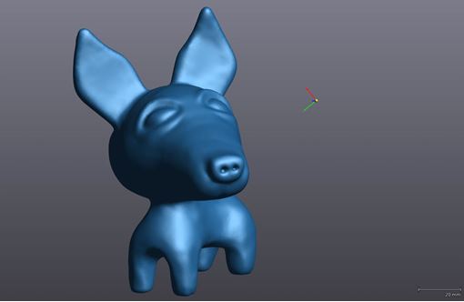
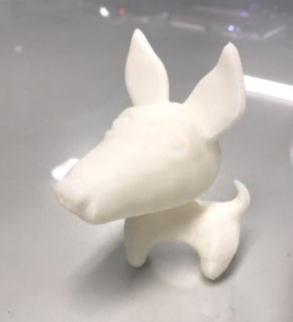
In VXscan i can export as STL file, so i send to Makerbot 2x and this is the result
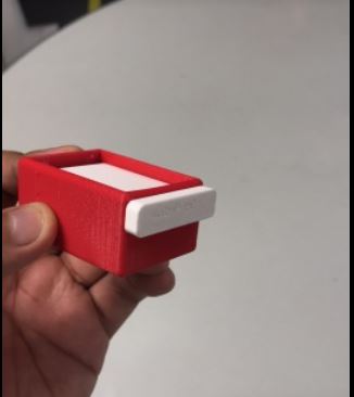
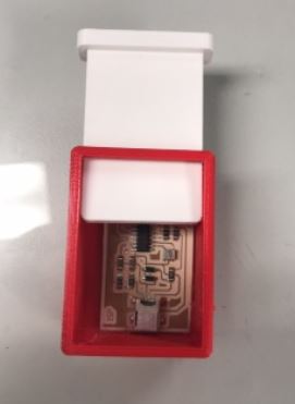
I printed a case for my ISP board
What did I learn from the tests?
I learned that the minimum angle of inclination that the FDM can print, specifically the makerbot replicator is 25 degrees, also that the minimum thickness of any object is 1 millimeter.
If you design 2 pieces to assemble it is necessary to give a certain tolerance, in my case I found that 0.4 mm of tolerance in the design fit well. As for the 2X, it is necessary to give the bed 135 degrees Celsius of temperature so that the ABS adheres well and does not take off in the middle of work.
Another thing I learned was to be careful with open meshes, this usually happens if you use software such as rhinoceros, the print goes wrong.
Be careful with the temperature of the place, for example once the air conditioner was turned on at 17 degrees Celsius, the ABS and PLA filaments did not extrude well
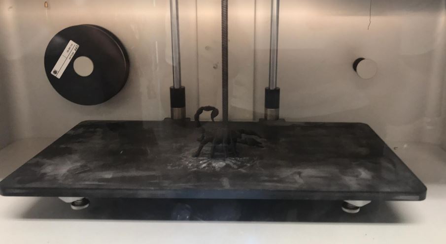
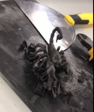
For this task, we tested the printers in the laboratory, in my case i used Mark II of Markforged.
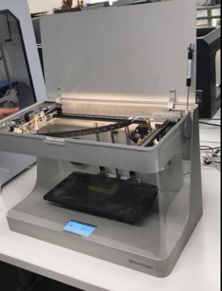
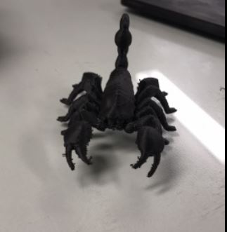
I downloaded a model from thingiverse and print it
Downloads Dog STL
Coil Solidworks
Coil STL
Case ISP STL
Case ISP Solidworks
Propeller Solidworks
Propeller STL
To see the complete development of the group assignment visit the following link that corresponds to the CIT page