Week five: Electronics Production
ISP
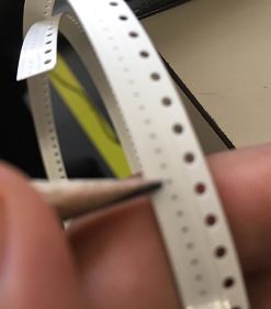
This week we had to make a programmer for AVR microcontrollers. First, i tried to make the board designed by Neil, but the capacitors of 0.1 uF that we have are too small to be soldered.
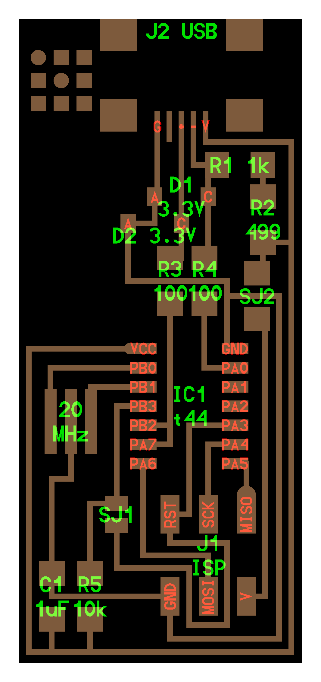
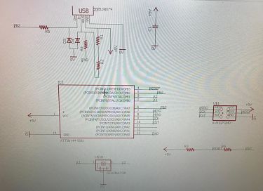
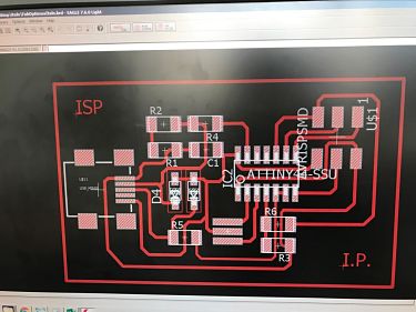
So, i decided to change the design of Ali according to the materials that we had, using Eagle.
I exported my design as PNG image with 1024 of resolution, and have to be monochrome
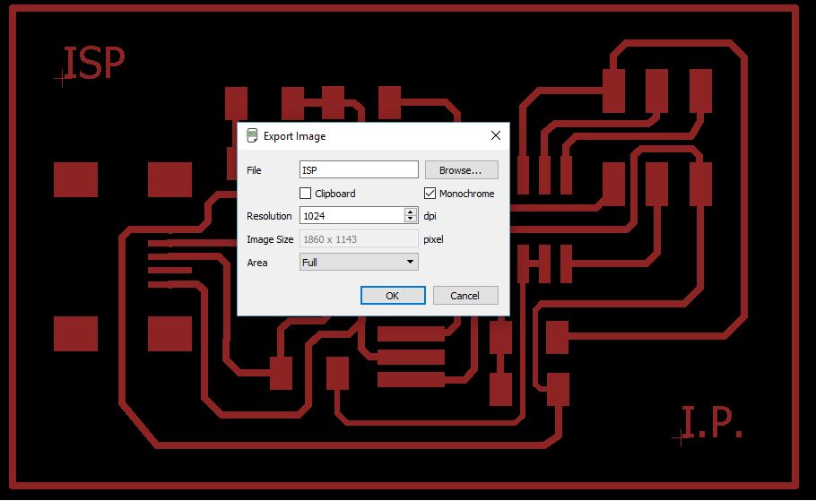
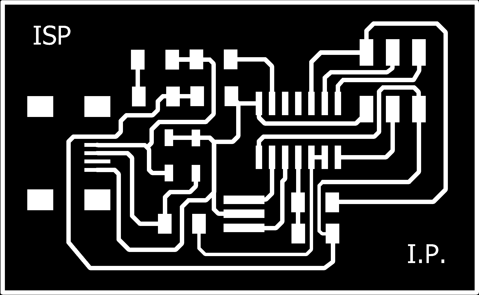
MY PNG FILE
Next step is do the CAM, i used Fab modules with these specifications
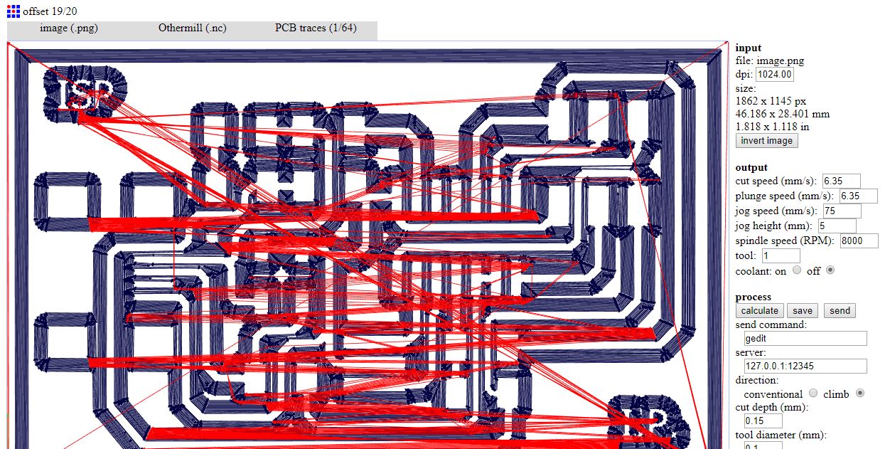
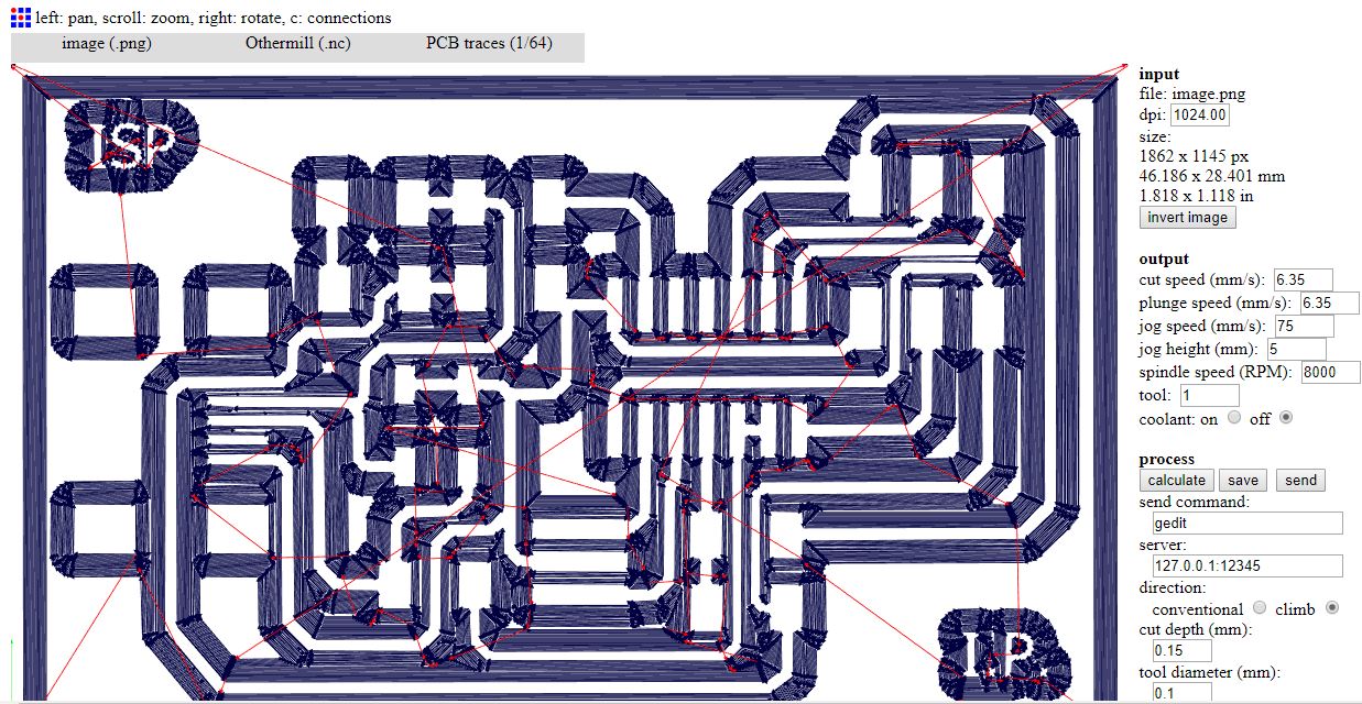
Milling
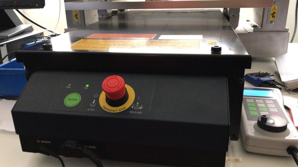
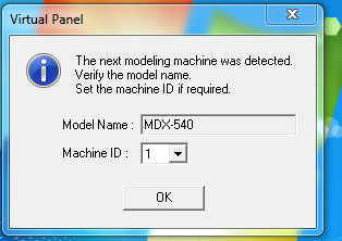
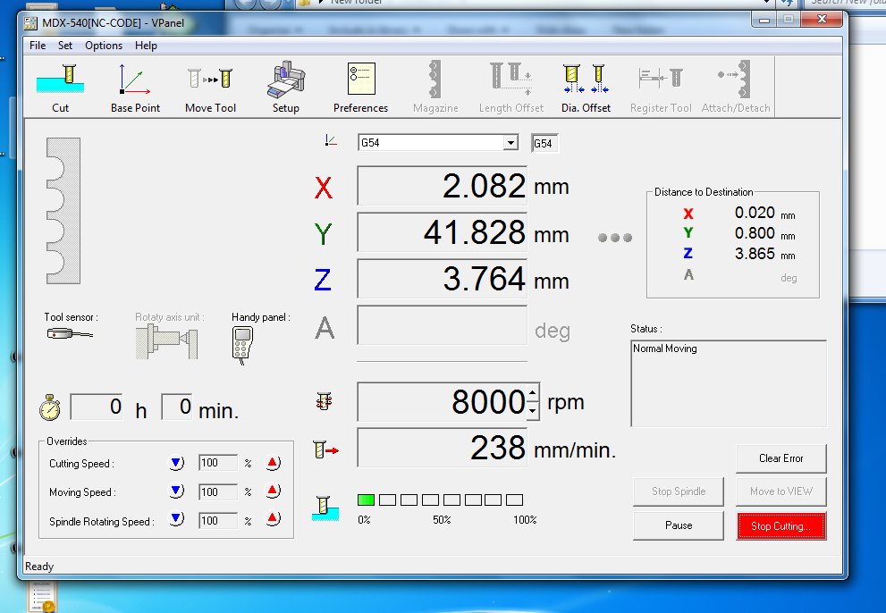
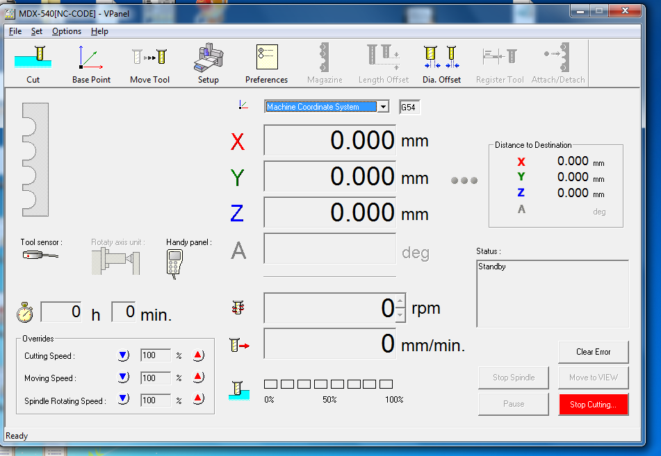
I got the G-code in nc format so i transfered the archive to Roland's computer and opened in "Vpanel" software after the calibration, as you can see in the screenshots
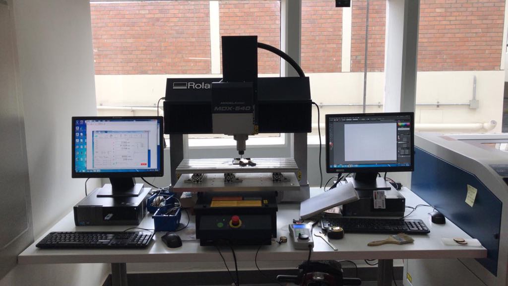
First we have to turn on the CNC machine, we have a Roland MDX-540
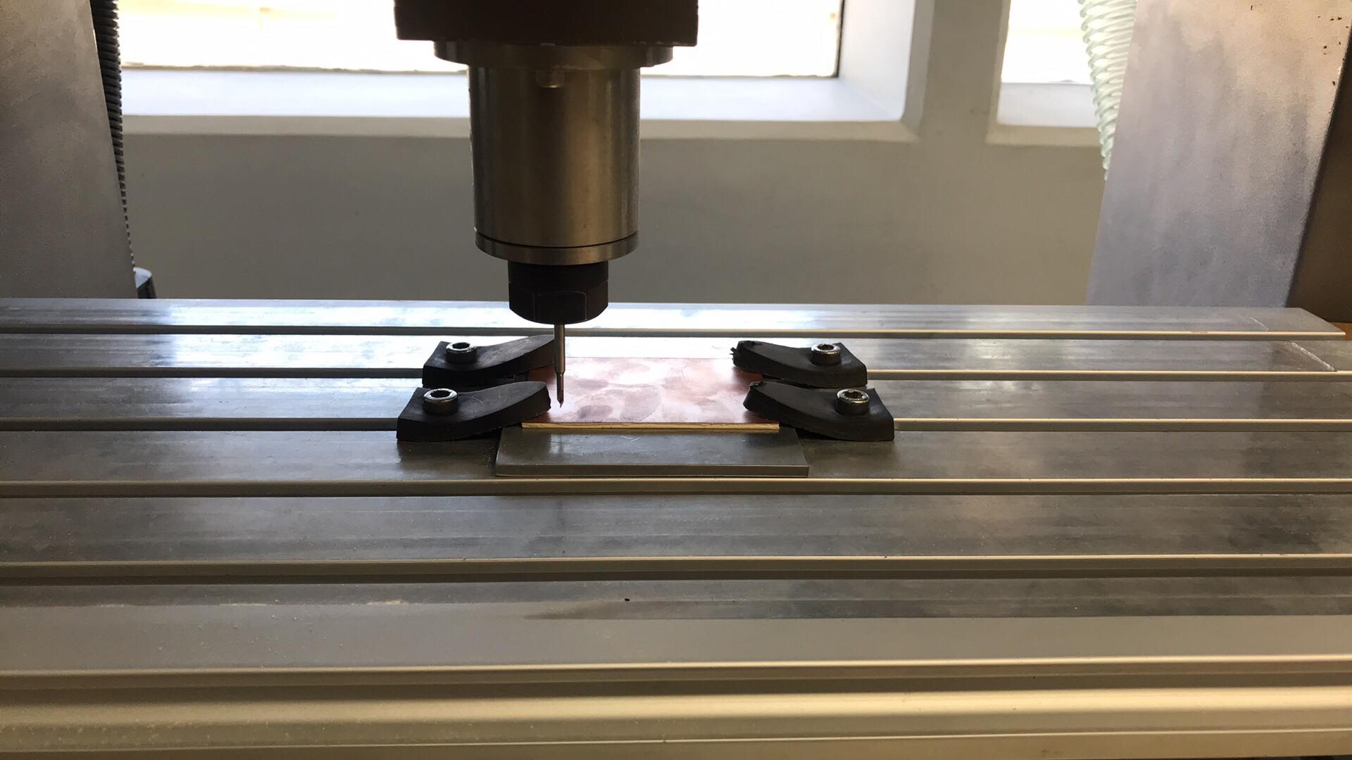
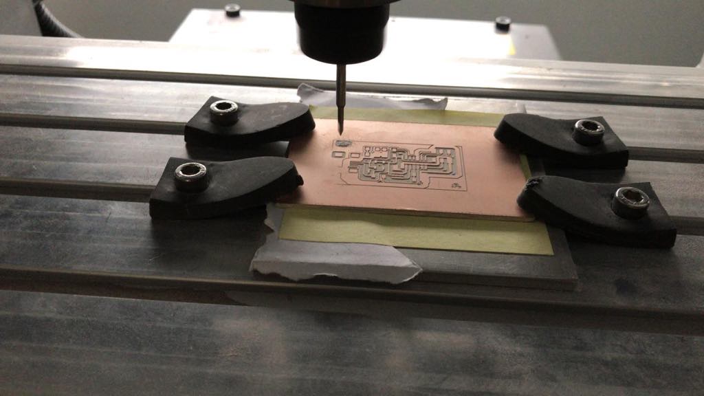
Then put the board in the correct place to start the calibration
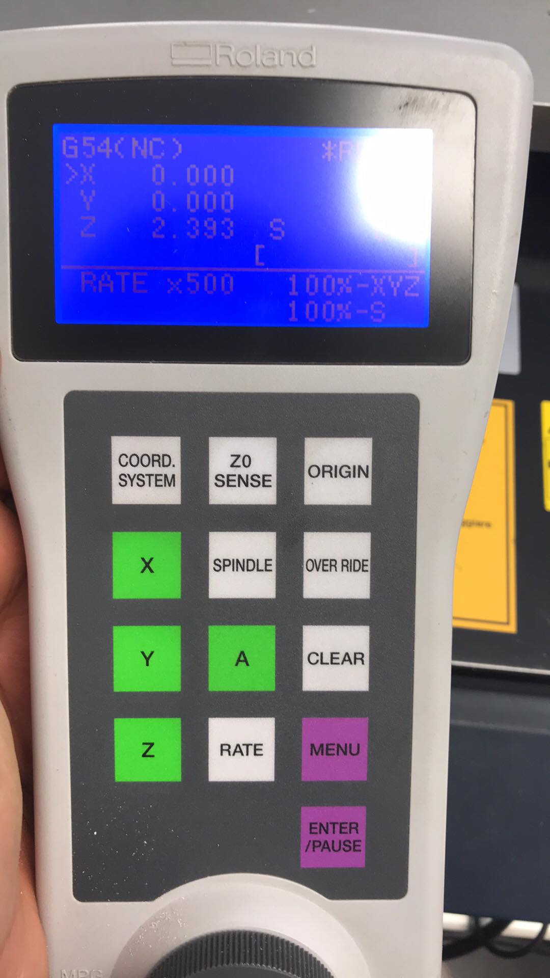
First, calibrate X and Y axis,putting the mill in the left corner.
Then, select the axis and press origin
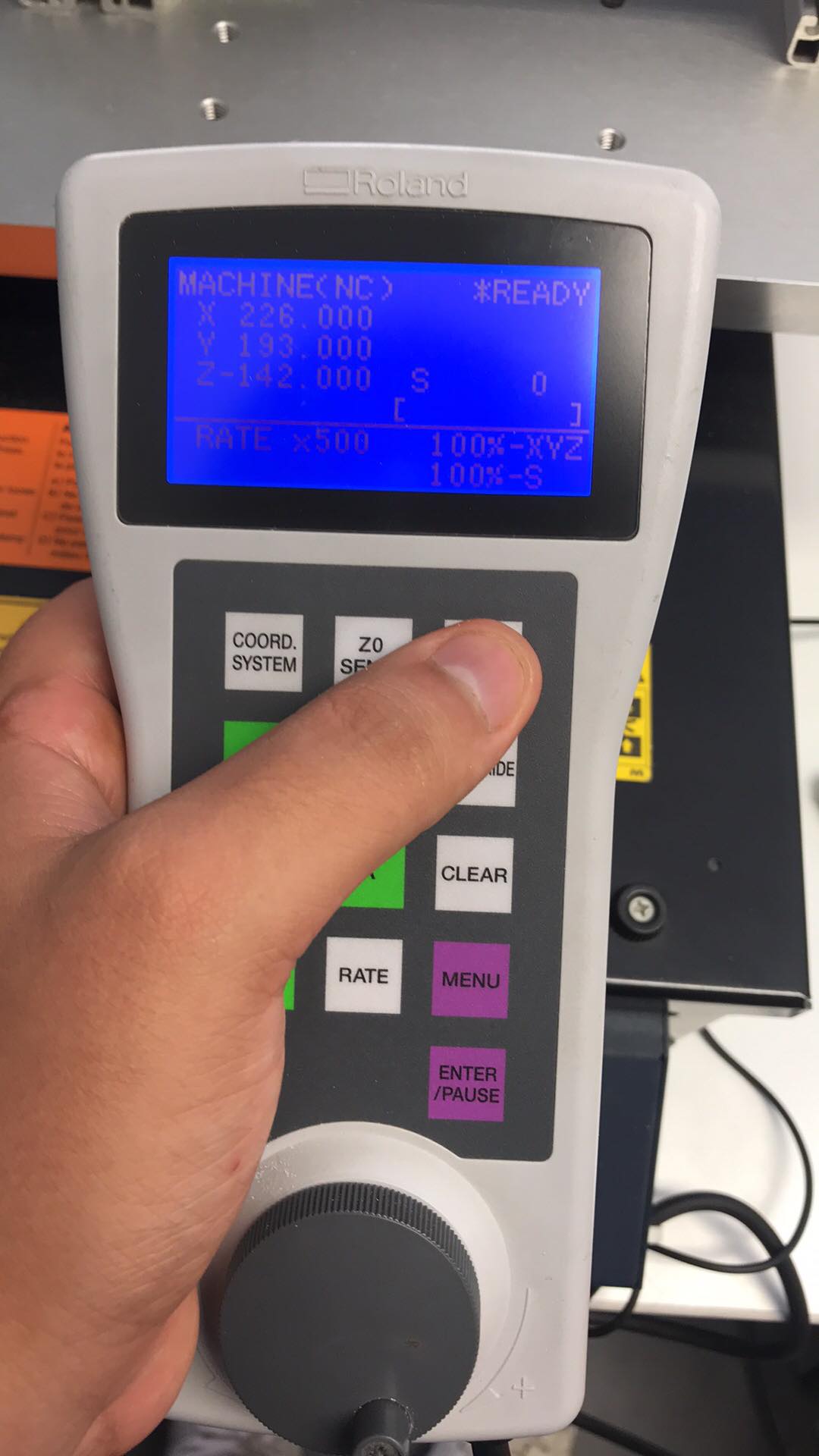
As you can see, X and Y have the zero position
To calibrate Z axis we have to use the calibration tool and put the mill few centimeters over the tool
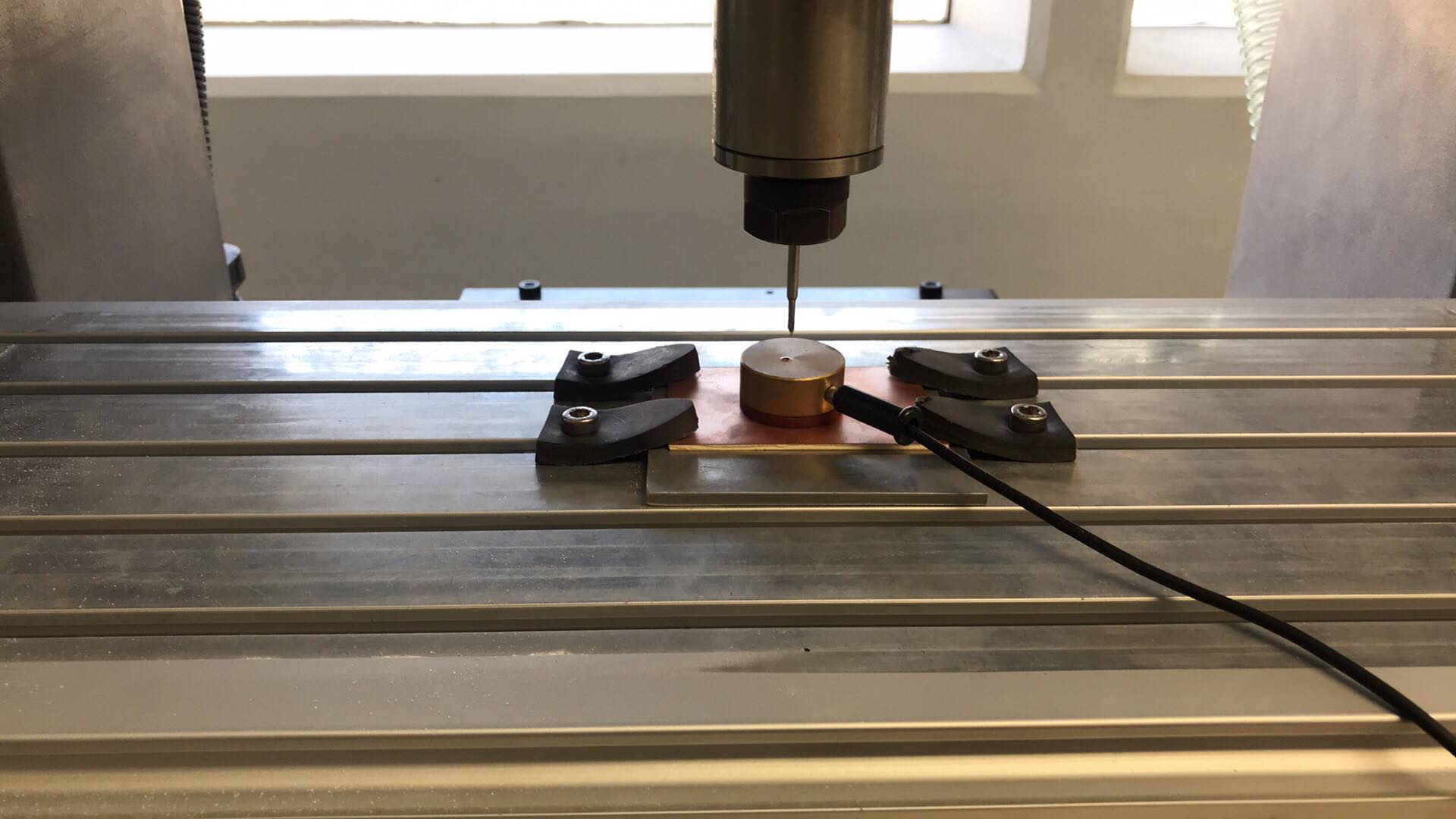
Then, press Zsense button
Calibration complete, 0 in 3 positions
I opened the archive with G-code
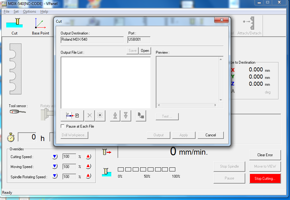
Play!
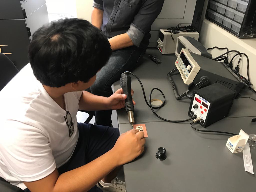
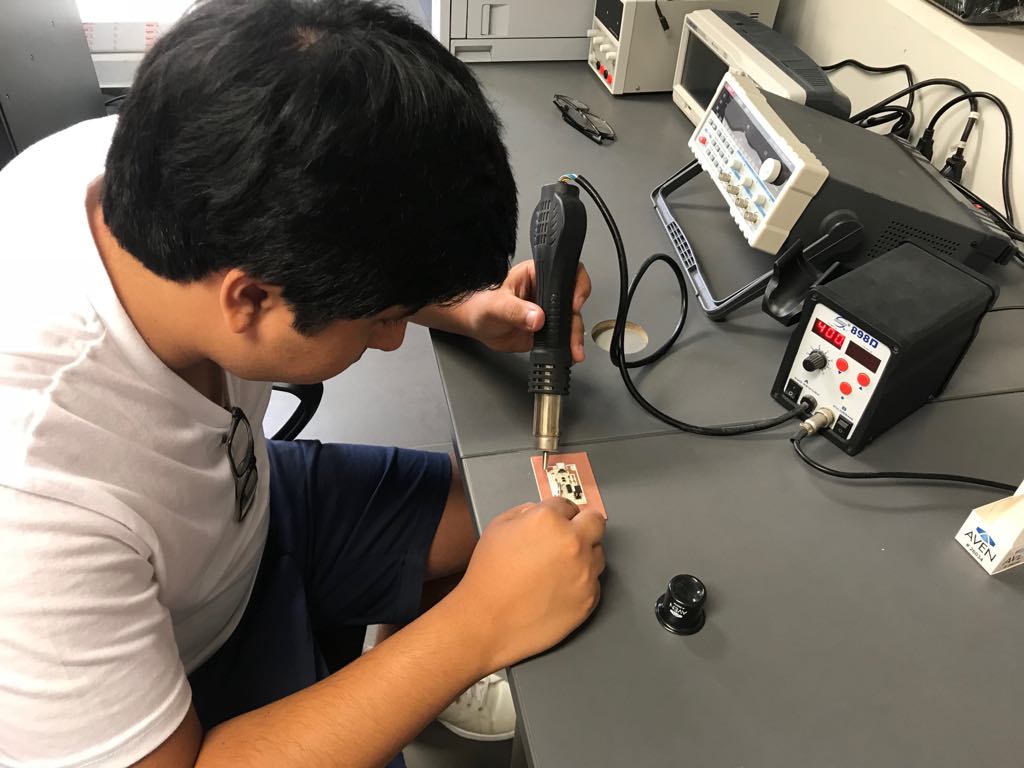
Time to solder
Since I am going to solder SMD elements, I used the flux method and heat gun
This method consists of placing a paste of liquid tin or flux with the help of welding aids in the copper spaces where the SMD elements will be placed, once the elements are placed in the paste, I used a heat gun at 400 degrees Celsius and I directed it towards the paste, the flux at this temperature melts and solidifies in a few seconds, holding the SMD component and transmitting the flow of electrons due to its nature of conductor
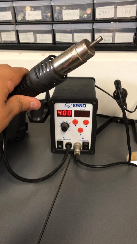
This image shows how I direct heat to the paste with the SMD element
For me it is easier to first solder the resistors, capacitors, pinheaders and leave the microcontroller in this case Attiny44 for the end, since it has smaller and thinner legs, also if it soldered it at the beginning it would be subjected to heat constantly and that could spoil to the component
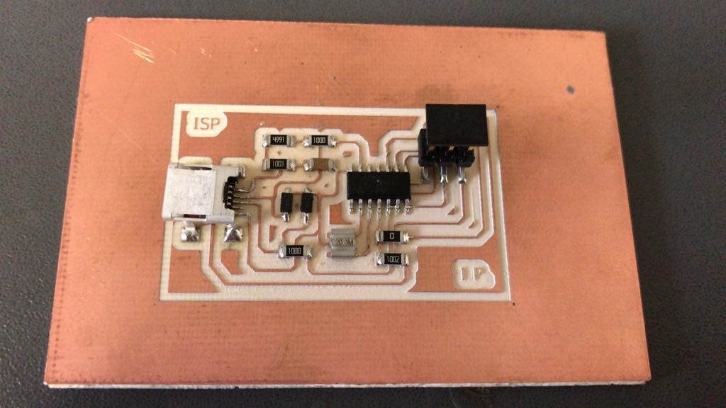
I checked with a multitester, apparently its fine, so i decided to connect to AVR power.
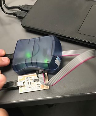
When i connected the AVR to my ISP, a green light turn on, so for now, the board is fine but we have to program first to know if the board works fine
Now i have to program the ATtiny44, i used a laptop with ubuntu, following the tutorial
Make clean

Make hex
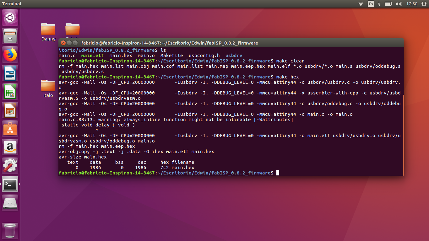
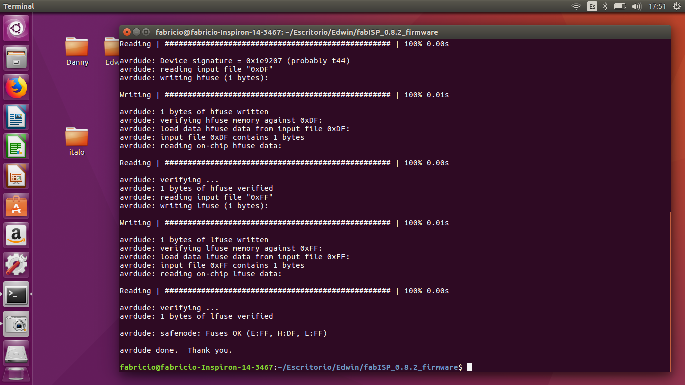
Make fuse
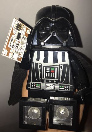
Hero shot!
My device manager recognizes my ISP after downloading some drivers that I will show in week 9

Grupal Assignment
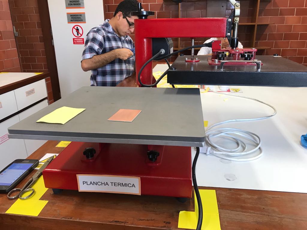
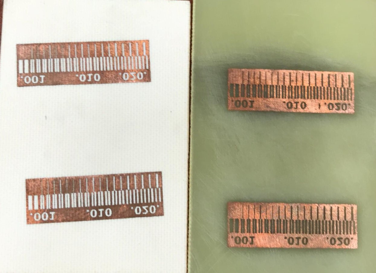
For the grupal assignment we wanted to compare 2 methods to make boards, the advantages and quality, in my case i made a board following acid method
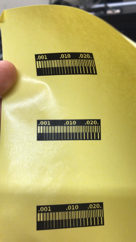
First, i printed the image of the board in couche paper
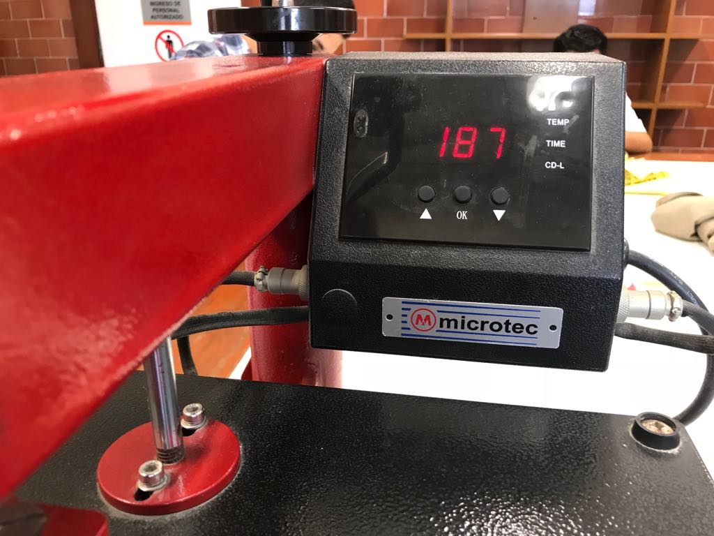
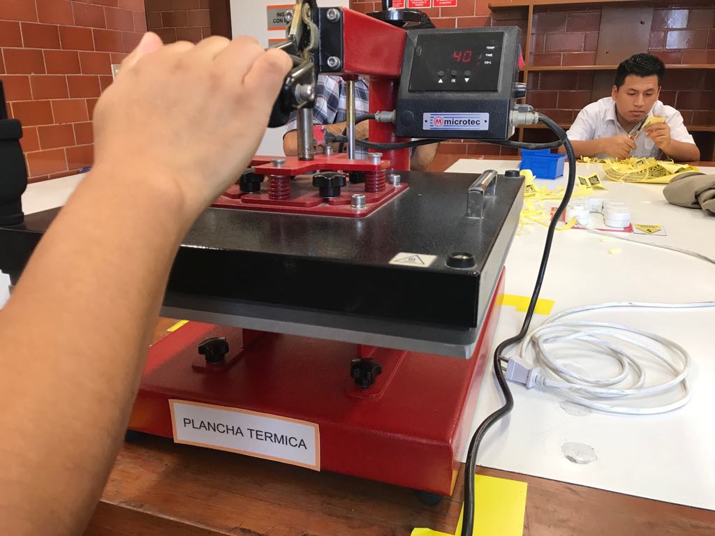
I prepared 2 boards, one of ceramic and one of fiberglass. And turn on the thermal plate until 190ºC approximately
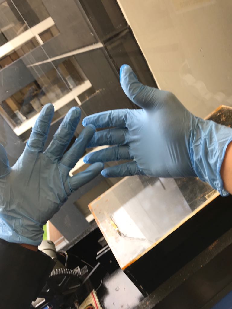
Ready to put the bords in acid, but first i have to wear gloves.
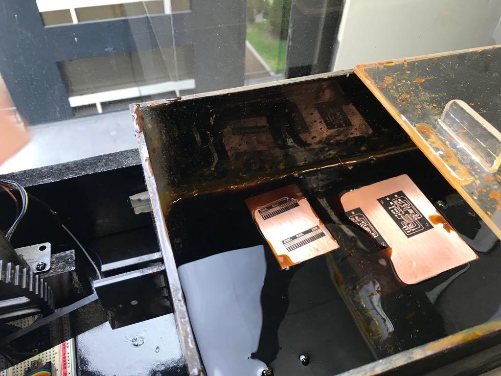
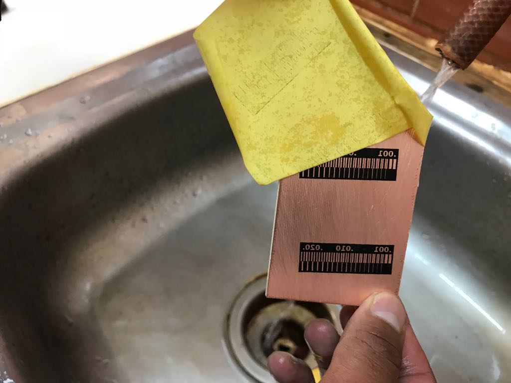
7 minutes in acid
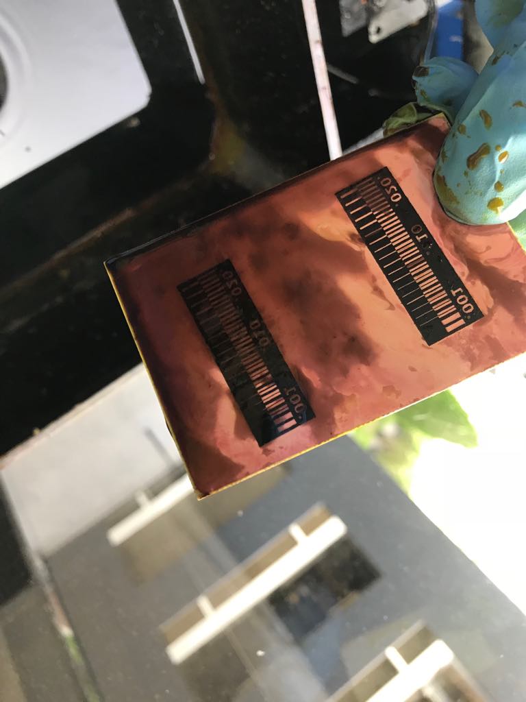
16 minutes in acid and the copper dissapeared
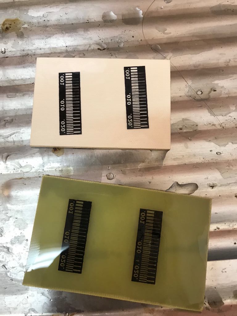
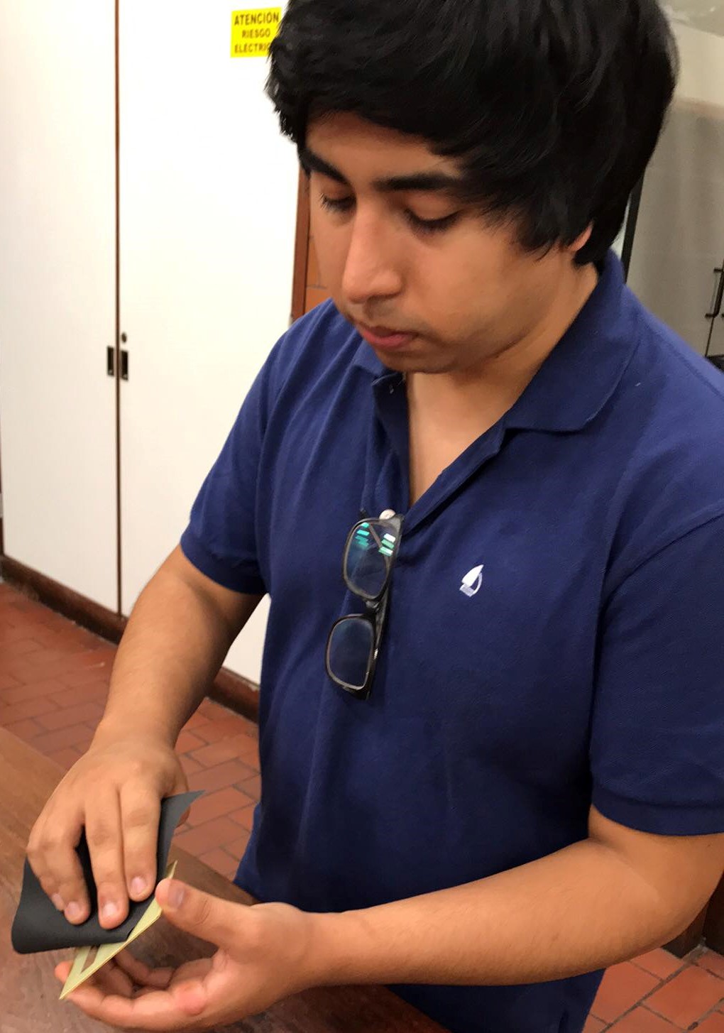
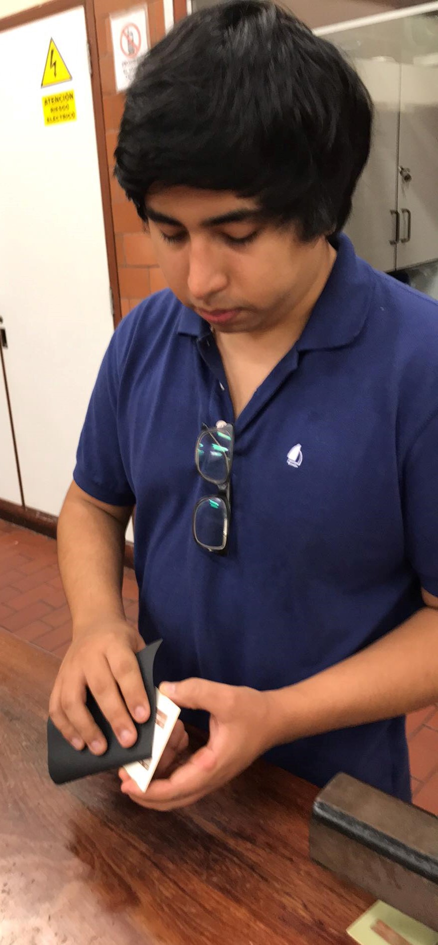
Then, i have to sand the boards
This is the final result
Download files here!
SchematicBoard
PNG board
G-code
To see the complete development of the group assignment visit the following link that corresponds to the CIT page