3D Scanning and Printing.
For the assignment of the 6th week, it will be divided into 5 differentiated parts: Design, 3D Printers, How to print something, Scanning and a group assignment.
Design
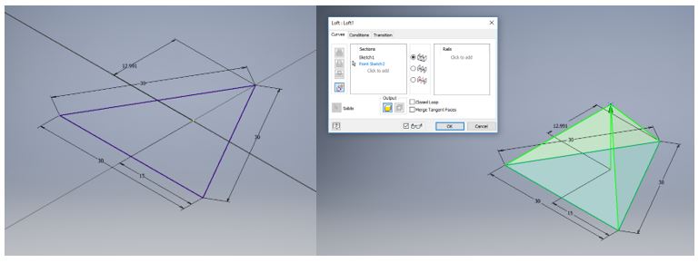
In this week we have to understand the correct functioning of a 3D printer and the limitations they have. To accomplish that, it is proposed to design a small piece that is not subtractive to test the printers.A triangle with the indicated measurements is drawn, on a superior plane a point is drawn and finally we use the loft tool to draw the triangle.
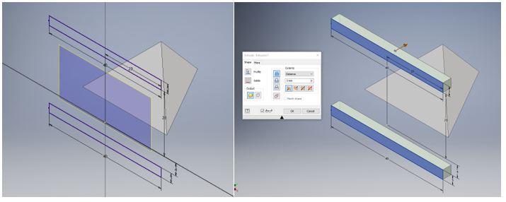
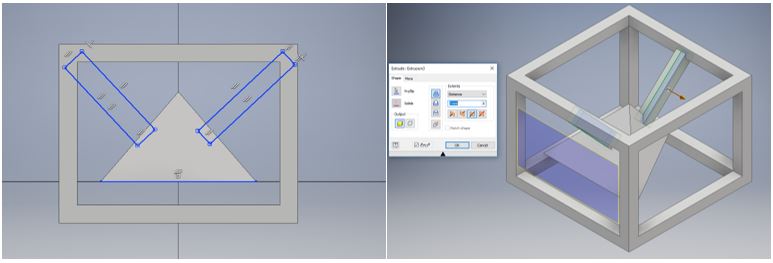
 Then, draw rectangles 20mm away from the center of coordinates and draw a rectangle to extrude it, as shown in the pictures.
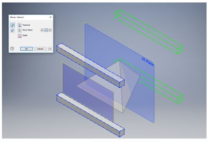
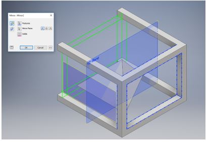
 Finally, a mirror is made with respect to the central plane to obtain the following
 The previous steps are repeated to obtain the final cube.
 To finish, we draw some rectangles to be able to hold the inner pyramid.
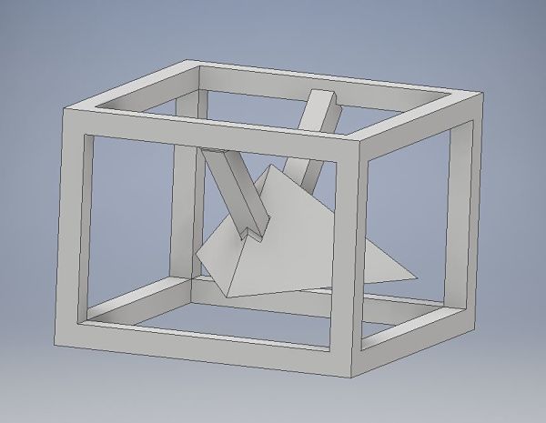
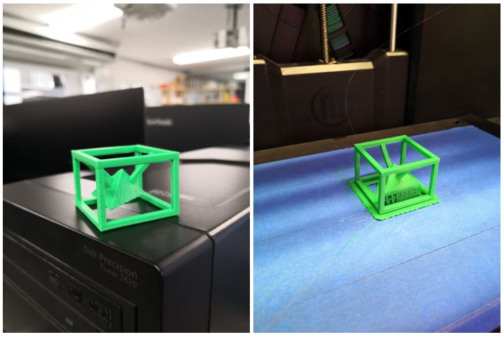
 The final result is the following picture.
Why is not be substractively
A piece that is not subtractive means that it can be machined by a lathe or a milling machine in a simple way or without additional accessories, besides it must be a single piece without assembling it in parts. If we manage to make a piece with these characteristics, the only way to make it is with the use of 3D printers, to achieve this goal I designed the following design using the Software Inventor:
As you can see, to make this design in a subtractive way is very complicated, since additional axes would be needed in CNC machines. It consists of a pyramid inside a hollow cube.3D Printers
A 3D printer is an additive type CNC machine, meaning that it is injecting material to make the designed prototype. For my assignment I will use the Makerbot replicator + printer with a PLA filament (Polylactic acid). Nowadays exist six types of 3D Printers: FDM (Fused Deposition Modeling), SLA (Stereolithography), SLS (Selective Laser Sintering), Material Jetting, Binder Jetting and Power Bed fusion. In the laboratory we only have FDM and SLA.FDM
Is an additive manufacturing process that belongs to the material extrusion family. In FDM, an object is built by selectively depositing melted material in a pre-determined path layer-by-layer. The materials used are thermoplastic polymers and come in a filament form. More information here.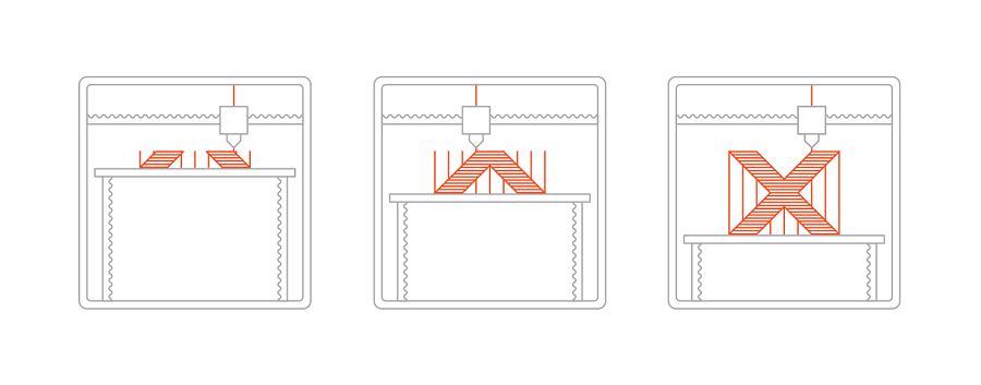
SLA
Is an additive manufacturing process that belongs to the Vat Photopolymerization family. In SLA, an object is created by selectively curing a polymer resin layer-by-layer using an ultraviolet (UV) laser beam. The materials used in SLA are photosensitive thermoset polymers that come in a liquid form. More information here.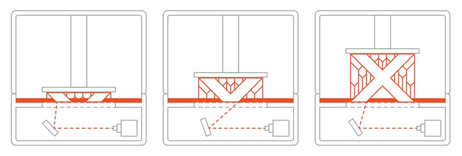 For my assignment I will use the Makerbot replicator + printer with a PLA filament (Polylactic acid), this printer is an FDM type.
Tech-specs of 3d printer
The printer is Makerbot brand, specifically the replicator + model, the printer features are as follows:| Print Technology | Fused Deposition Modeling |
| Build Volume | 29.5 L X 19.5 W X 16.5 H CM |
| Layer Resolution | 100 microns |
| Material Diameter | 1.75 mm |
| Nozzle Diameter | 0.4 MM |
| Material Compatibility | MakerBot PLA Material, MakerBot Tough Material |
| Extruder Compatibility | Smart Extruder+, Tough Smart Extruder+, Experimental Extruder |
| Connectivity | USB, Ethernet, Wi-fi |
How to print someting
The first thing we must understand is the difference between the formats .stl and .obj. The .stl format describes the shape of the object by defining the coordinates of all the vertices of all triangles that a surface may be subdivided into. This means that in STL any curved surface is represented with an approximation of many very small faces.OBJ is also somewhat common, but it was originally developed for computer graphics, not manufacturing, and as such is able to store information like the texture images to be applied to the surface, which are of no use in the 3D printing world. In other words, this format is a CAD format.
In this case, I only use .stl format to print. To obtain this type of format, we should only use the save as in the inventor software option and look for the .stl format.
Limitation and parameters
Then we start to modify the printing parameters such as infill, raft and support. In this way we can see what are the limitations of the printers to obtain an optimal result.This section is only for some tests, the conclusions will be seen in the next section.
Test 1
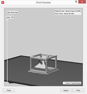
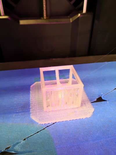
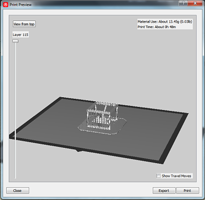
For the first impression, the default parameters of the printer are used, the only thing that I modify is the position of the printing, as you can see in the pictures.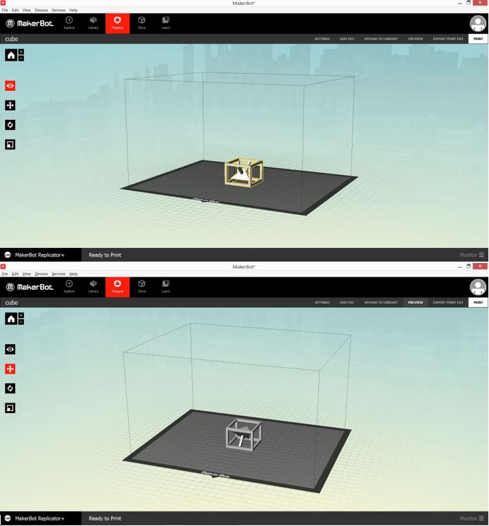 This are the default parameters:
| Layer height | 0.2mm |
| Infill | 10% |
| Extrude temperature | 215ºC |
| Raft to model Spacing | 0.32mm |
| Raft Margin | 4.0mm |
| Support Density | 0.2 |
 |
 |
 |
 |
Test 2
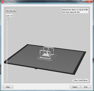
Now it is time to change some parameters to print, I change these parameters| Infill Layer height | 0.30mm |
| Infill Density | 15% |
| Infill pattern | Hexagonal |
| Raft to model Spacing | 0.36mm |
| Raft Margin | 10.0mm |
| Support Density | 0.2 |
 |
 |
Test 3
For this test, I put less material and support, these are the parameters:| Infill Layer height | 0.25mm |
| Infill Density | 3% |
| Infill pattern | Diamond |
| Raft to model Spacing | 0.36mm |
| Raft Margin | 10.0mm |
| Support Density | 0.1 |
 |
 |
Conclusions
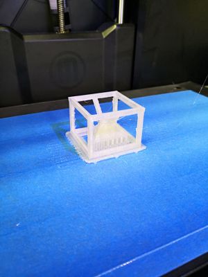
Test 1
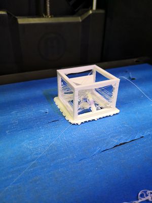
For this experiment, we can see that in the Test Up print, some small threads are formed with respect to the other test, this is due to the firmware installed in the printer and the temperatura of the extruder.
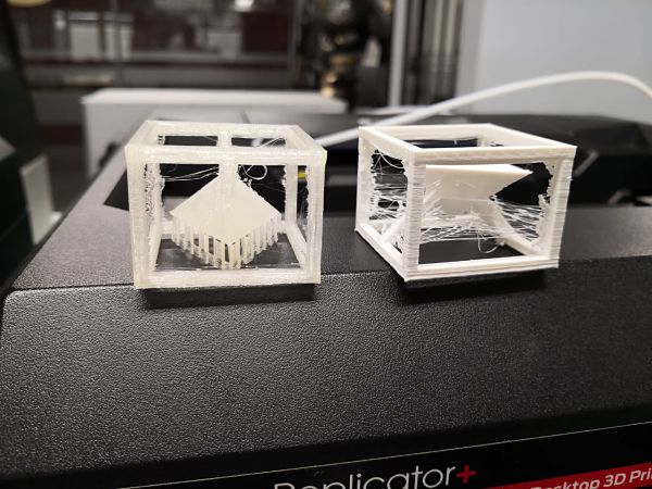 For the form of the orientation, the extruder is required to make many travels moves, so it was decided to start doing other tests only with the test down.
Test 2
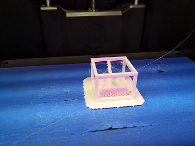
Having less filling, when removing the support, we realized that the pieces that hold the internal pyramid is quite weak, so it is not recommended to have so little filling in these designs to avoid breaks.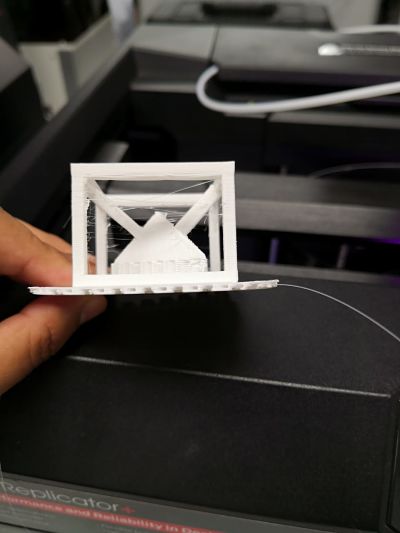 Finally, we appreciate that by increasing the raft, we have a uniform bed to the whole piece, which makes it easier to remove the raft from the piece and the print is cleaner.
By printing the object in this way, the extruder performs fewer movements obtaining fewer leftover threads.
Finally, we appreciate that by increasing the raft, we have a uniform bed to the whole piece, which makes it easier to remove the raft from the piece and the print is cleaner.
By printing the object in this way, the extruder performs fewer movements obtaining fewer leftover threads.Test 3
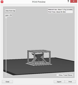
Reducing the infill of the object, in addition to reducing its density and smaller support, the printer forces to create more support to obtain an optimal result, then you can appreciate in greater detail the additional support that creates the printer.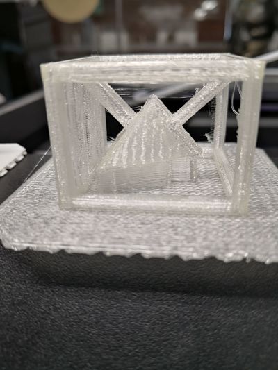
As a final conclusion, we realize that as we make an impression with less infill, the printer is forced to create more support, which makes it difficult to eliminate it once the design finishes printing.
Eliminate "spider webs"
Tests were conducted to eliminate these small networks, after many tests in the laboratory, it was found that a temperature at which these networks are eliminated.The best working temperature is 200ºC, then the image of the result.
 Finally, I believe that the best parameters were used in the second test and modifying the temperature of the extruder at 200ºC.
Scanning
In our Laboratory we have the scanner HANDYSCAN 700 OF CREAFORM like the picture: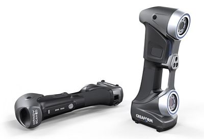 The HandySCAN 700 offers increased accuracy and resolution. It is the most versatile 3D scanner on the market for inspection and demanding reverse engineering.
Technical Specs
The technical specs are:| Accuracy | Up to 0.030 mm |
| Resolution | 0.050 mm |
| Light source | 7 laser crosses (+1 extra line) |
| Scanning area | 275 x 250 mm |
| Output formats | .dae, .fbx, .ma, .obj, .ply, .stl, .txt, .wrl, .x3d, .x3dz, .zpr |
| Measurement rate | 480,000 measurements/s |
How to scan?- Workflow
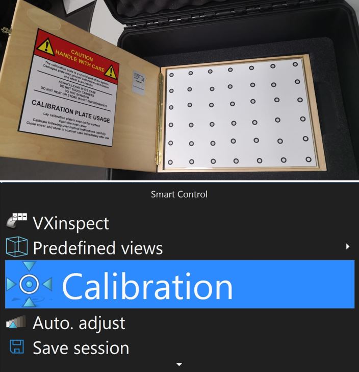
To make a correct scan with the HandyScan, we must perform an orderly workflow.- Calibration. The calibration process requires a template that is included with the scanner. From the software, the calibration option is selected, as seen in the picture.
- Scanning targets. Once the scanner is calibrated, we must place the targets in the scanning area and the object to be scanned.
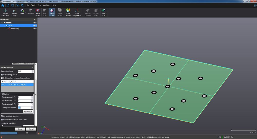
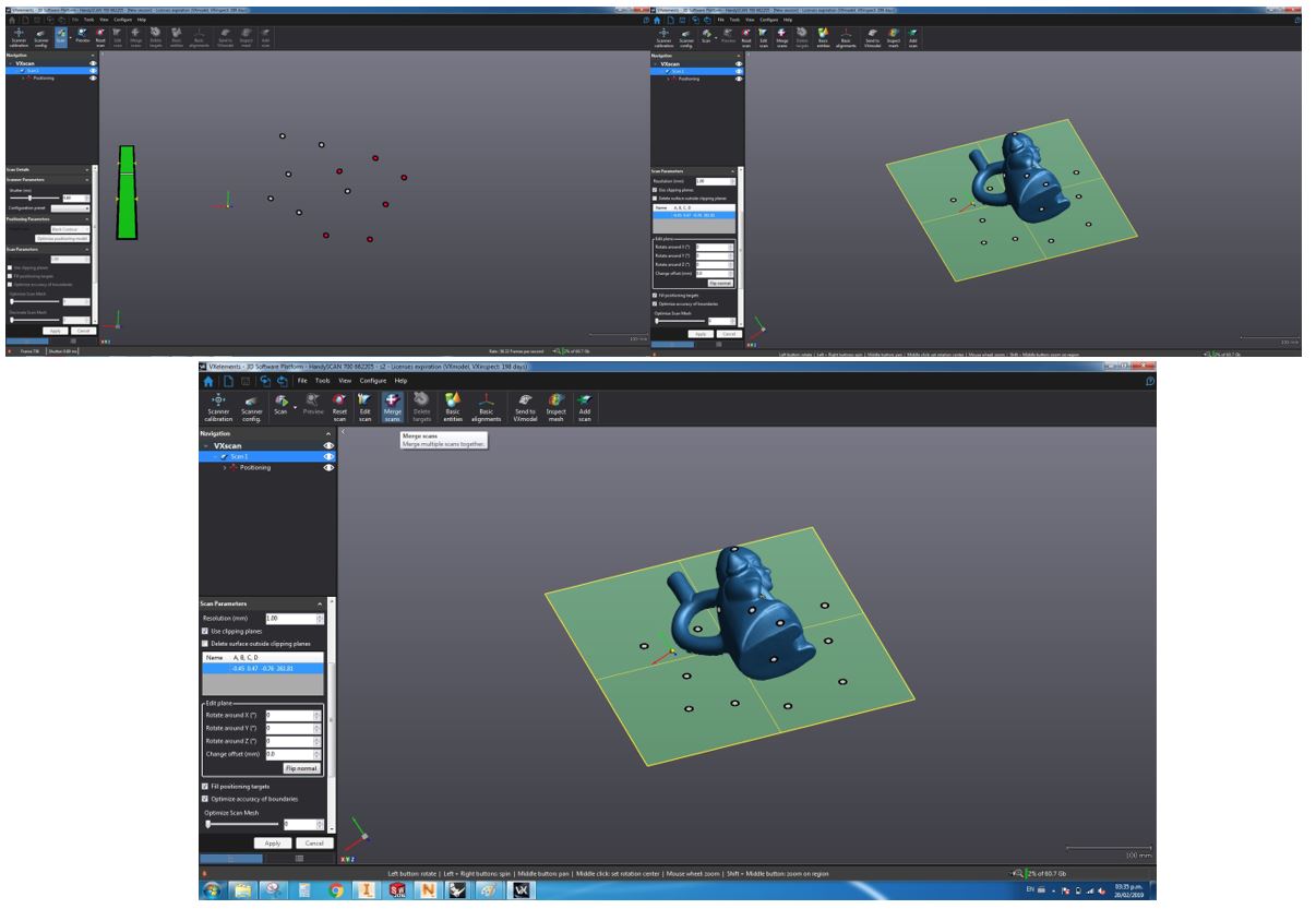
- Create plane. What we can see in the software are all the targets found, which are those of the scanning plane and the targets of the object to scan.
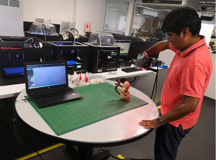
- Scanning objetc Once the new plane has been obtained, it is time to scan the object obtaining some results as shown in the picture.
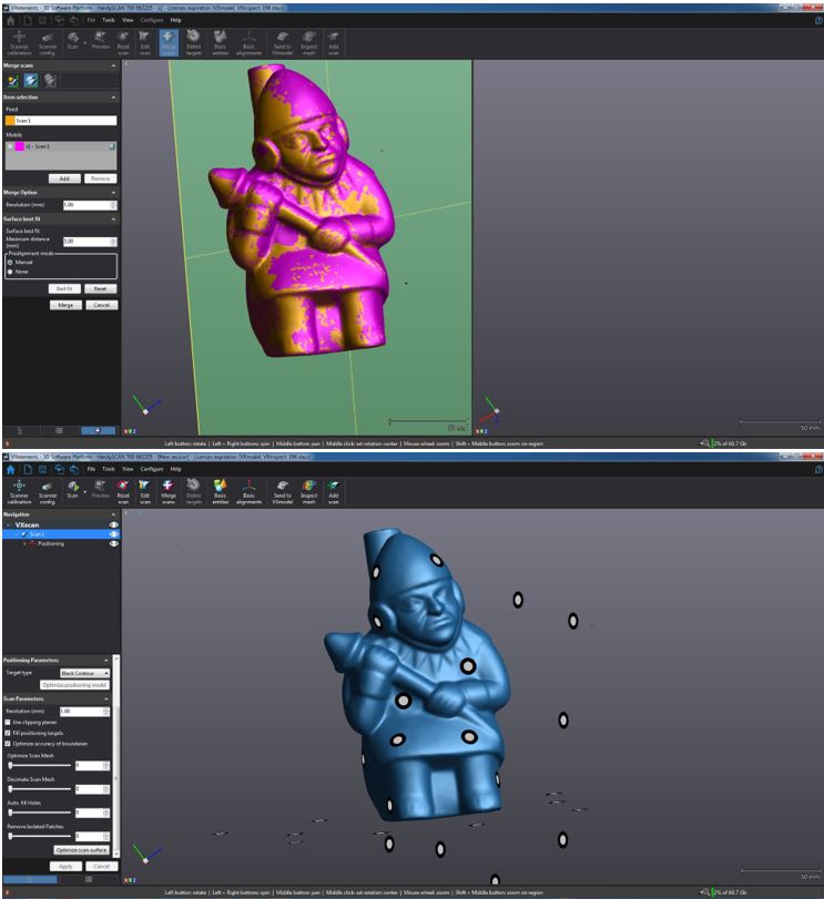
- Mesh edition At the end of the scan, you must make a mesh edition, this serves to soften the surface of the scanned object.
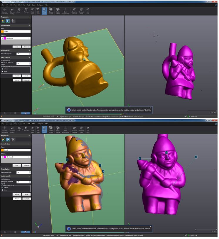
- Mesh fusion In the processes of scanning, in cases we cannot cover the entire surface of the object. In this example it was not possible to scan the lower parts and the base, which is why the scan session must be saved for to perform another scan without having to recalibrate or create the plane. Once the new scanning session is done, a merge fusion is performed in order to obtain the result.
- Export File Now, it is time to export the file like a inventor: Save as/complete.stl
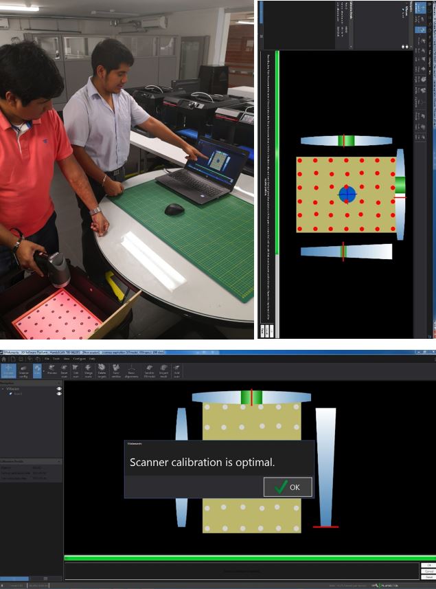
 The objective of the calibration is to focus on the points requested by the software in order to start the work.
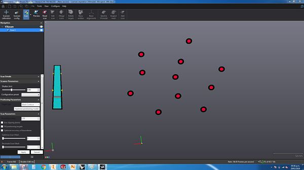
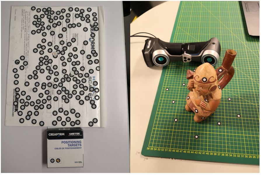 After having placed the targets, you start with the recognition process of all the targets.
 We must select 3 targets to create a plane with an offset of 1 mm. The objective of doing this is to be able to differentiate the object with the scanning area.
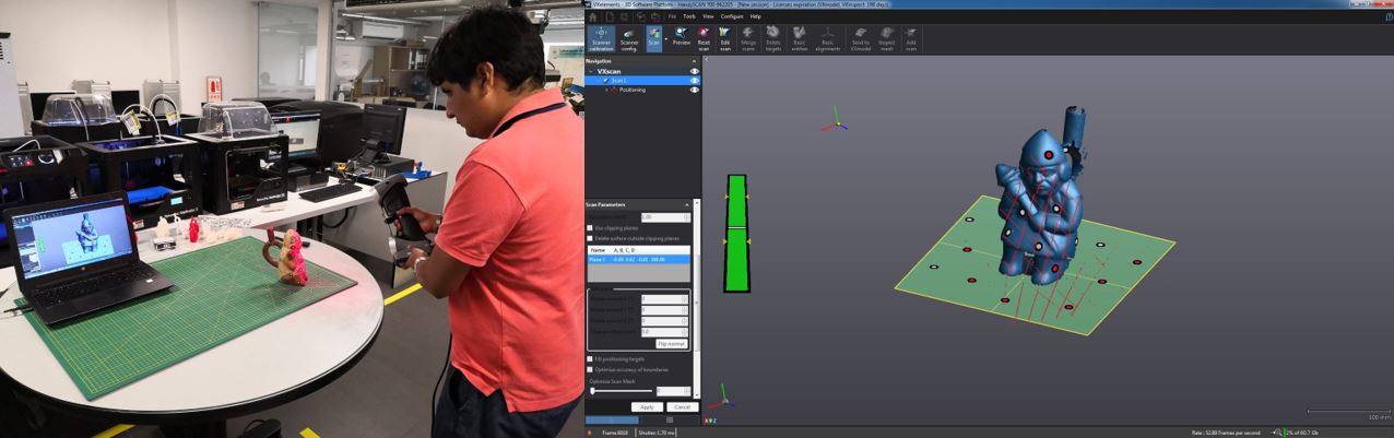
 When performing the merge fusion, we will have both sessions in parallel, the objective is to identify common points so that the object can be realigned, as shown in the picture.
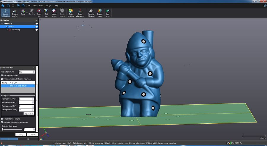
 The result is the one shown in the image. In my case I had to make 3 scans to be able to close all the holes in the object, even in some cases I increased the targets to reach those spaces I needed.
Only for this case, I upload the file in another server, because the file have to much MB for my repository.
What i have learn?
This scanning process I understood that it is necessary to perform more than one scan to obtain an optimal result, even a lab partner did not manage to close all the points with which he had to perform an action called freeform, in which he had to sculpt his work. This action may demand more work time if needed.Another interesting process that can be obtained from scanning is reverse engineering. That means that once the object is scanned, we can modify its design from a design software, such as the Inventor or Solidworks.
Group assignment
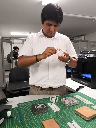
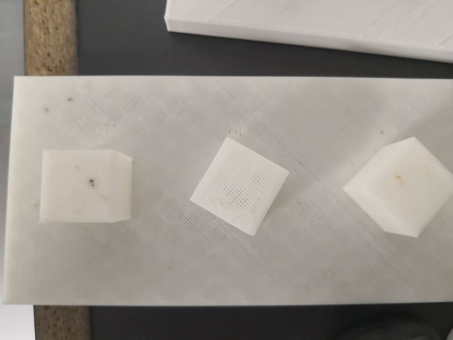
In our group assignment, we have tested all the lab printers: Makerbot replicator 2, replicator 2x, Replicator +, Markforged and Nobel XYZ. We can see a picture of all the tests we have done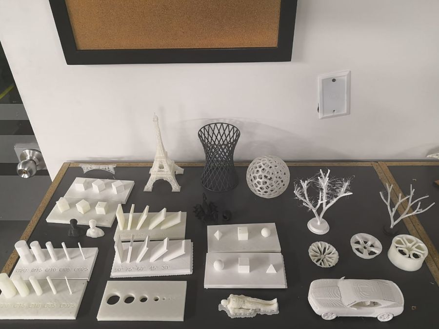 As a personal contribution, I printed the following objects in order to check if the impression is similar to reality.
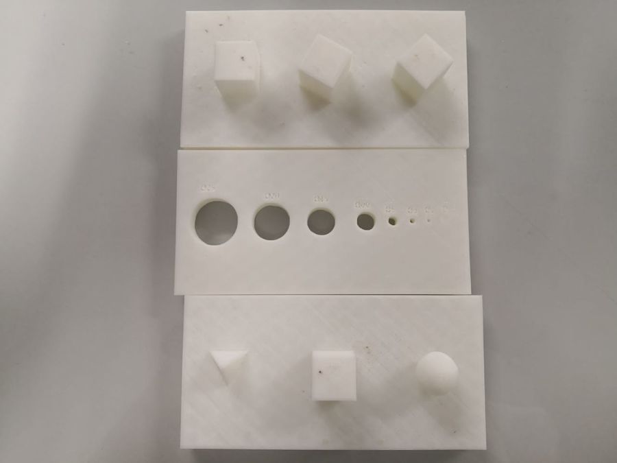 It is observed in the printing of the squares that the 90º, 60º and 30º angles are not appreciated, but if they meet the angles
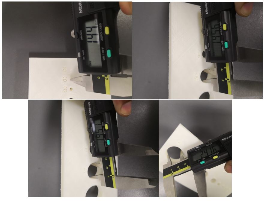
 In the design of the holes we can see that there is a difference of -0.5 in the holes of 20mm diameter less. In the case of the 25mm hole we see a greater difference, of almost 0.8mm.
This information will be very valuable when creating designs with holes and respect tolerance.
In the design of the holes we can see that there is a difference of -0.5 in the holes of 20mm diameter less. In the case of the 25mm hole we see a greater difference, of almost 0.8mm.
This information will be very valuable when creating designs with holes and respect tolerance.
 To see all the documentation of the group work, you can visit the CIT page.
Download files
You can download this files Here:Design. (Inventor 2017)
Scanner result.
Scanner object for Makerbot software.
Test angle. (STL)
Test hole. (STL)
Test polygon. (STL)