5. Electronics production
This week was Electronics Production. These were the assignments
- Getting familiar with the CNC machine
- Familiarizing with the bits and accessories
- Design rule character
- milling the PCB for ISP of ATTiny family of ICs
- soldering the Components
- Programming the board
Roland SRM 20
It is a desktop milling machine which is popular in the field of Rapid Prototyping. The Machine Specs are as follows:
- Speed: ~8000 RPM
- Default collet size: ~6mm
Operation
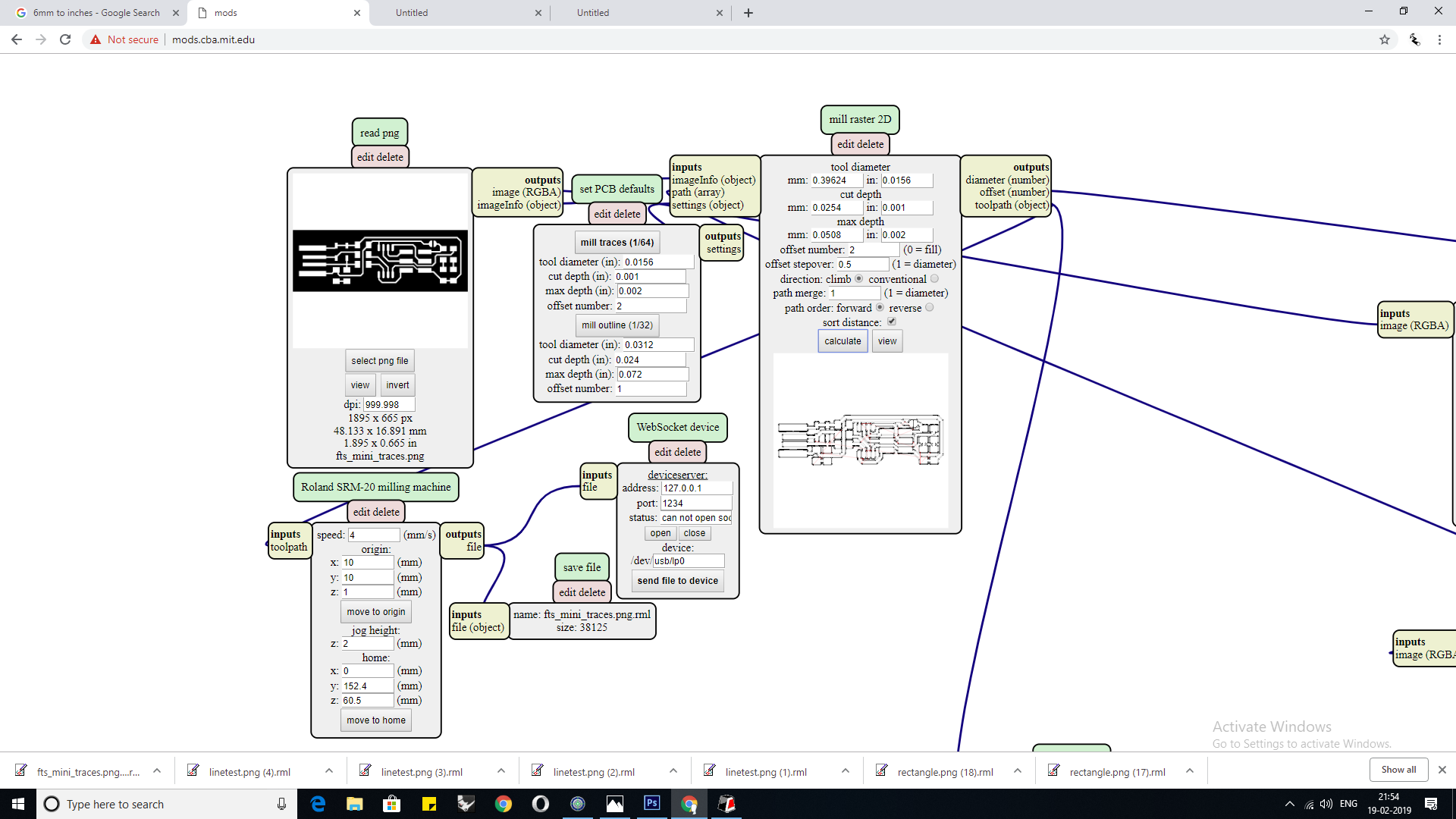
First I created an .rml file of the board traces using mods and then uploaded it into a software called V-Panel, once added i then ran the machine without loading neither the bit nor the board in the air just to verify if everything was running smoothly here, i noticed that there no way to track the progress. For that my instructor suggested me to try Modela Virtual.
Preparation
Preparation involves Three things they are the Sacrificial layer, Board and the Router bits.
Sacrificial layer:
As the name suggests, Sacrificial Layer is flat piece of plastic that is mounted in the router so that we can avoid damaging the surface of the router which is calibrated to maintain the level.
Preparation
To prepare the sacrificial layer, we must first mount it carefully onto the surface and tighten the sacrificial layer.
Make sure not to tighten the layer too hard as it can warp the layer.
After mounting the sacrificial layer onto the surface bed, we have run a pass through the sacrificial layer so that the sacrificial layer can become even in any case where the layer couldn’t be loaded properly. I have used 6mm, 4 flute bit to even the layer.
Board
We will be working with FR-1 PCB. FR-1 is a hard, flat material that consists of a thin layer of copper over a non-conductive phenolic resin. It’s usually about the thickness of two or three credit cards. While making a PCB we will run the router twice once to mill the traces and once to remove the outline.
Preparation
Apply double sided tape to the backside of the board. Remove the tape and fix it onto the sacrificial layer(see that it is firmly fixed). Load the bit(This is a job that requires complete your attention). Carefully check the Z-axis origin.
The double sided tape must not be foam type.
Router Bits
There will be three types of bits we will use in this Process, they are 1/64, 1/32 and 0.01. We use the 1/64 bit for milling the traces, 1/32 bit for outlines. However the shank sizes also vary, the Roland SRM-20’s Collet supports upto 6mm shank diameter for smaller diameters(3 or 4mm) we will require an optional collet or a converter. The bits come in various combinations with variations in the shank sizes, end mill types(flat or rounded),size and number of flutes and also with various coatings.For this application we use a standard type of bit which has fixed number of flutes, shank size, type of end mill(flat) and as mentioned earlier, bit size.
Preparation
Loading the bits is something that should be done with utmost care as the bits can be delicate. First, in order to load the bit carefully remove it from its container. Then take the bit with your index and middle finger of one hand and load it into the Collet by guiding the shank with the other hand.
Using finger gloves help you in having a better grip on the bit.
After loading the shank hold it while tightening the grub screw. Be careful as to not put too much pressure while tightening the grub screw.
The pressure should as much as enough to tear a single sheet of paper.
Useful links
The link below will help you understand more about the machine and also gives you a much more detailed description on various features and softwares that will be helpful in using the machine.
Board design
This week we will be using two designs one is to determine the design rule characteristics, the other is a programmer board to program ICs. As the design was already tried and tested I will just download the PNG files and run them through mods.
PCB Manufacture
While manufacturing a PCB we must be careful about a few things like loading the bits, placement of the board, Origin positions, etc.
Sacrificial Layer
Starting with the Sacrificial layer I had initially loaded a bit not knowing that it was damaged and ran the machine it milled the layer without stopping however the layer was too rough upon inspection we realized that the end tip of one the flutes was damaged after replacing the bit we ran it again, this time the layer became smooth.
Bits
Always be careful with the origins an cut depths, especially Z-Axis if we are not careful the bit will ram into the board and break the bit, for milling the traces we will be using 1/64 bit. The board I will be using has a thickness of 1.5mm so I must calculate the layer thickness and enter into the mods terminal, for milling I used the cut depth of 0.001mm and a max depth of 0.002mm.
Initially the bit went too deep so I paused the program and checked the parameters in which we found that I loaded the bit a with the collet in the wrong position.
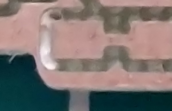
After resetting the bit i ran the machine this time the bit would mill the first trace round however after the first round the bit instead of going a step down it would go all the way up and run the remaining rounds in the air, after discussing it we concluded that it must have hit some limit switch and the machine is resetting itself. We changed the parameters and the machine milled the traces.
Soldering
Populating the board was one of the most enjoyable and challenging tasks this week this was first time working with the 1206 family of SMDs or SMDs of any kind. Just during handling of these components I lost an LED and a resistor, searching these components on the floor requires the focus of a monkey trying to find a bug in another monkey, i was only able to find the resistor.
Tools
The tools were,
- Soldering station
- PCB Vice
- Tweezers
- Magnifying Lens
- Desoldering Pump
- Desoldering Tweezers
Use the PCB Vice or soldering mat it helps the board be stationary.

Components
I used the 1206 family of components the components required are listed below
- 1x ATtiny45 or ATtiny85
- 2x 1kΩ resistors
- 2x 499Ω resistors
- 2x 49Ω resistors
- 2x 3.3v zener diodes
- 1x red LED
- 1x green LED
- 1x 100nF capacitor
- 1x 2x3 pin header
I didn’t have 49 & 499Ω resistors so I used the nearest available higher value which were 51 & 510Ω.

Checking your work
After populating the board make sure to do a continuity check, there must be no short(short circuit).
We can do this using a multimeter, turn the dial to continuity mode as shown below.

While running the contiuity test you must hear the buzzer which indicates that the connection doesn’t have a short.
Programming the board
While going through these steps I followed Brian’s Documentation Which was easy to follow. I installed the drivers and followed the steps, since I used windows I had to do a few extra steps. I installed GNU Make, AVRdude and Zadig with ease but it took quite some time to search the GNU toolchain, the link Provided redirected to Microchip’s website there was nothing there, even the search showed some random results.
Here is the LINK which takes you to the location in the official site from which you can download or you can go to this LINK from GITHUB. The reason I am putting these two links is initially the source code from the official site worked the first time and then it didnt work the second time(This will be explained further down below).
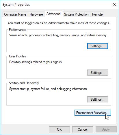
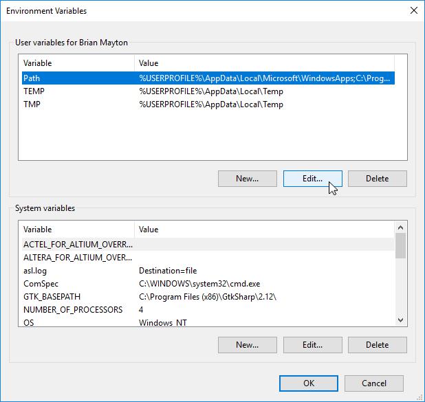
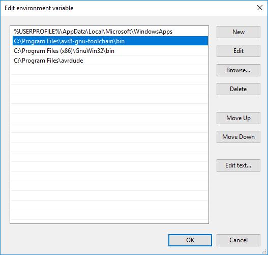
I installed them and updated my environment variables as mentioned in the documentation which is as follows:
The three values to add are:
C:\Program Files\avr8-gnu-toolchain\bin

C:\Program Files (x86)\GnuWin32\bin

C:\Program Files\avrdude
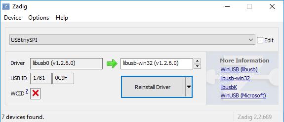
I then Installed the drivers using Zadig.
As mentioned earlier I followed Brian’s Documentation there were some speed bumps which I plan to document.
Initially I faced an error while doing the sanity check,
avrdude -c usbtiny -p t45
avrdude.exe: Error: Could not find USBtiny device (0x1781/0xc9f)
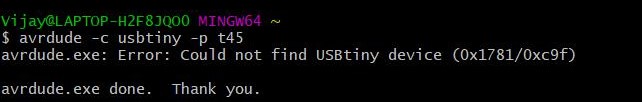
Brian’s Document mentioned about this error which I knew that this would happen because I was not using a fabbed board but a commercial AVR Programmer. so I changed the programmer and used my instructor’s ISP Board.
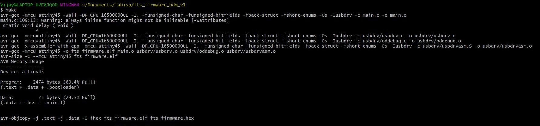
I then downloaded and extracted the firmware source code. After extracting I opened BASH terminal and ran the command make which created a hex file.
These are the files you get in the folder
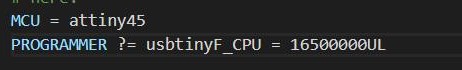
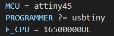
Of these file open the ‘makefile’ in a text editor like Notepad or a source code editor like visual studio or brackets. I use Microsoft visual studio as a default source code editor and I highly recommend it simply because the code looks cleaner and easy to understand. Initially I used notepad and got an error in bash when I tried to execute make command
Vijay@LAPTOP-H2F8JQO0 MINGW64 ~/Documents/fabisp/fts_firmware_bdm_v1
$ make
avr-gcc -mmcu=attiny45 -Wall -DF_CPU=16500000UL -I. -funsigned-char -funsigned-bitfields -fpack-struct -fshort-enums -Os -Iusbdrv -c main.c -o main.o
process_begin: CreateProcess(C:\Program Files\avr8-gnu-toolchain\bin\avr-gcc, avr-gcc -mmcu=attiny45 -Wall -DF_CPU=16500000UL -I. -funsigned-char -funsigned-bitfields -fpack-struct -fshort-enums -Os -Iusbdrv -c main.c -o main.o, ...) failed.
make (e=193): Error 193
make: *** [main.o] Error 193
Initially I didn’t understand what had happened when I tried to Google it I couldnt find any answers too so i thought I will check the code again but thos time I opened the file in Visual studio this is where I knew what happened I rectified it and the error was gone.
Here I connected my board to the Third Party AVR Programmer which in turn I connected to the PC.

While using the Programmer I got an error message which says that the target board doesn’t answer to which the reason might have been the connections which when checked turned out to be right however after rectifying the wrong connections still showed the same error which just confused me, after several attempts to troubleshoot it didnt solve the error. We tried my Instructors Board to program my board and it was done successfully and now my board is also an ISP Programmer.
Next I executed the command make flash to erase the target chip and program its flash memory with the contents of the .hex file.
Now, run the make fuses command to set up all of the fuses except the one that disables the reset pin.
Now all that is left is to run the command make rstdisbl so that avrdude will never be able to reprogram the board accidentally.