
27/3/2019
Probe an input device's analog levels and digital signals
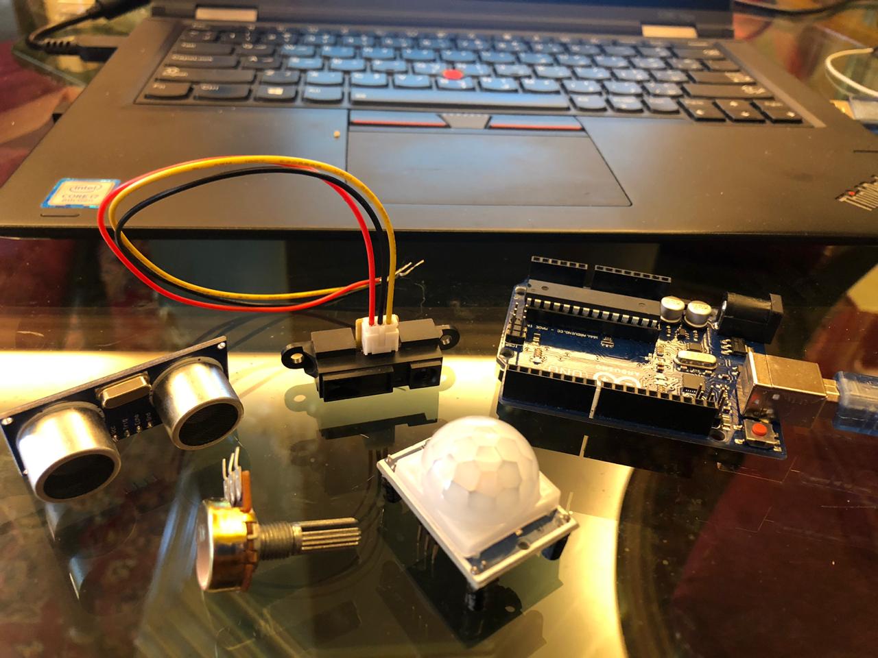
Measure something: add a sensor to a microcontroller board that you have designed and read it
For this assignment, I will test my inputs using ARDUINO UNO
The inputs that might be used for my final project are the following:
I have watched the following youtube video to help me out
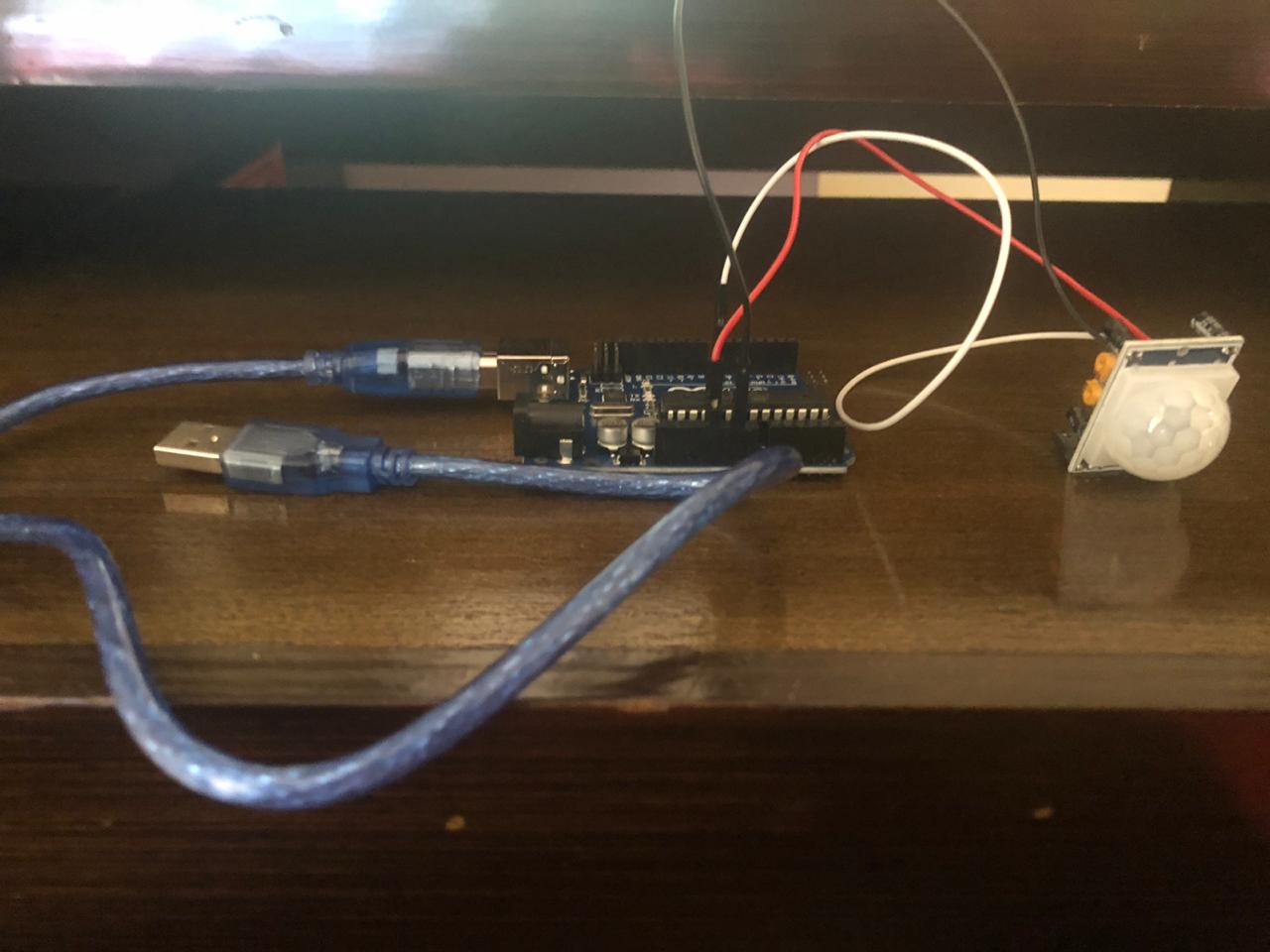
And I started to follow the steps as per the below in order to connect my PIR Sensor to the ARDUINO UNO
I found out that the PIR Sensor takes one digital pin from the ARDUINO in addition to VCC and GND of course
You may look at the connections in the images below
And for the coding part, I have used the one available on the ARDUINO website as per the below:
                             /*
 * //////////////////////////////////////////////////
 * //making sense of the Parallax PIR sensor's output
 * //////////////////////////////////////////////////
 *
 * Switches a LED according to the state of the sensors output pin.
 * Determines the beginning and end of continuous motion sequences.
 *
 * @author: Kristian Gohlke / krigoo (_) gmail (_) com / https://krx.at
 * @date:   3. September 2006
 *
 * kr1 (cleft) 2006
 * released under a creative commons "Attribution-NonCommercial-ShareAlike 2.0" license
 * https://creativecommons.org/licenses/by-nc-sa/2.0/de/
 *
 *
 * The Parallax PIR Sensor is an easy to use digital infrared motion sensor module.
 * (https://www.parallax.com/detail.asp?product_id=555-28027)
 *
 * The sensor's output pin goes to HIGH if motion is present.
 * However, even if motion is present it goes to LOW from time to time,
 * which might give the impression no motion is present.
 * This program deals with this issue by ignoring LOW-phases shorter than a given time,
 * assuming continuous motion is present during these phases.
 *
 */

/////////////////////////////
//VARS
//the time we give the sensor to calibrate (10-60 secs according to the datasheet)
int calibrationTime = 30;

//the time when the sensor outputs a low impulse
long unsigned int lowIn;

//the amount of milliseconds the sensor has to be low
//before we assume all motion has stopped
long unsigned int pause = 5000;

boolean lockLow = true;
boolean takeLowTime;

int pirPin = 3;    //the digital pin connected to the PIR sensor's output
int ledPin = 13;


/////////////////////////////
//SETUP
void setup(){
  Serial.begin(9600);
  pinMode(pirPin, INPUT);
  pinMode(ledPin, OUTPUT);
  digitalWrite(pirPin, LOW);

  //give the sensor some time to calibrate
  Serial.print("calibrating sensor ");
    for(int i = 0; i < calibrationTime; i++){
      Serial.print(".");
      delay(1000);
      }
    Serial.println(" done");
    Serial.println("SENSOR ACTIVE");
    delay(50);
  }

////////////////////////////
//LOOP
void loop(){

     if(digitalRead(pirPin) == HIGH){
       digitalWrite(ledPin, HIGH);   //the led visualizes the sensors output pin state
       if(lockLow){
         //makes sure we wait for a transition to LOW before any further output is made:
         lockLow = false;
         Serial.println("---");
         Serial.print("motion detected at ");
         Serial.print(millis()/1000);
         Serial.println(" sec");
         delay(50);
         }
         takeLowTime = true;
       }

     if(digitalRead(pirPin) == LOW){
       digitalWrite(ledPin, LOW);  //the led visualizes the sensors output pin state

       if(takeLowTime){
        lowIn = millis();          //save the time of the transition from high to LOW
        takeLowTime = false;       //make sure this is only done at the start of a LOW phase
        }
       //if the sensor is low for more than the given pause,
       //we assume that no more motion is going to happen
       if(!lockLow && millis() - lowIn > pause){
           //makes sure this block of code is only executed again after
           //a new motion sequence has been detected
           lockLow = true;
           Serial.print("motion ended at ");      //output
           Serial.print((millis() - pause)/1000);
           Serial.println(" sec");
           delay(50);
           }
       }
  }
And I have also tested the one in the youtube video above which has simpler command lines:
                            int val = 0;

void setup() {
  // put your setup code here, to run once:
pinMode(13, OUTPUT);
pinMode(3, INPUT);
}

void loop() {
  // put your main code here, to run repeatedly:
val = digitalRead(3);

if (val == HIGH)
{
  digitalWrite(13, HIGH);
}
if (val == LOW)
{
  digitalWrite(13, LOW);
}
}
The test can be checked in the below video:
I have watched the following youtube video to help me out
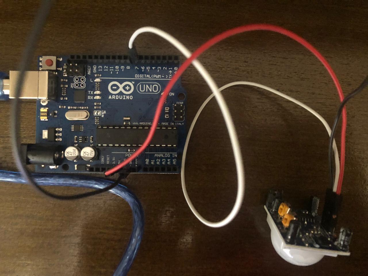
And I started to follow the steps as per the below in order to connect my IR Distance Sensor to the ARDUINO UNO
I found out that the IR Sensor takes one analog pin from the ARDUINO in addition to VCC and GND of course
You may look at the connections in the image below
And for the coding part, I have used the one available onthis website inside which you may download the zip file to be added to the Arduino library as per the below:
                             /*SHARP GP2Y0A21YK0F IR sensor with Arduino and SharpIR library example code. More info: https://www.makerguides.com */
//Include the library
#include
//Define model and input pin
#define IRPin A0
#define model 1080
/*Model :
GP2Y0A02YK0F --> 20150
GP2Y0A21YK0F --> 1080
GP2Y0A710K0F --> 100500
GP2YA41SK0F --> 430
*/
//Setup the sensor object
SharpIR IR_Sensor_1(IRPin, model);
void setup()
{
//Begin serial communication at a baud rate of 9600
Serial.begin(9600);
}
void loop()
{
delay(1000);
int distance_cm = IR_Sensor_1.distance();  // this returns the distance to the object you're measuring
Serial.print("Mean distance: ");  // returns it to the serial monitor
Serial.print(distance_cm);
Serial.println(" cm");
}
The test can be checked in the below video:
I have watched the following youtube video to help me out
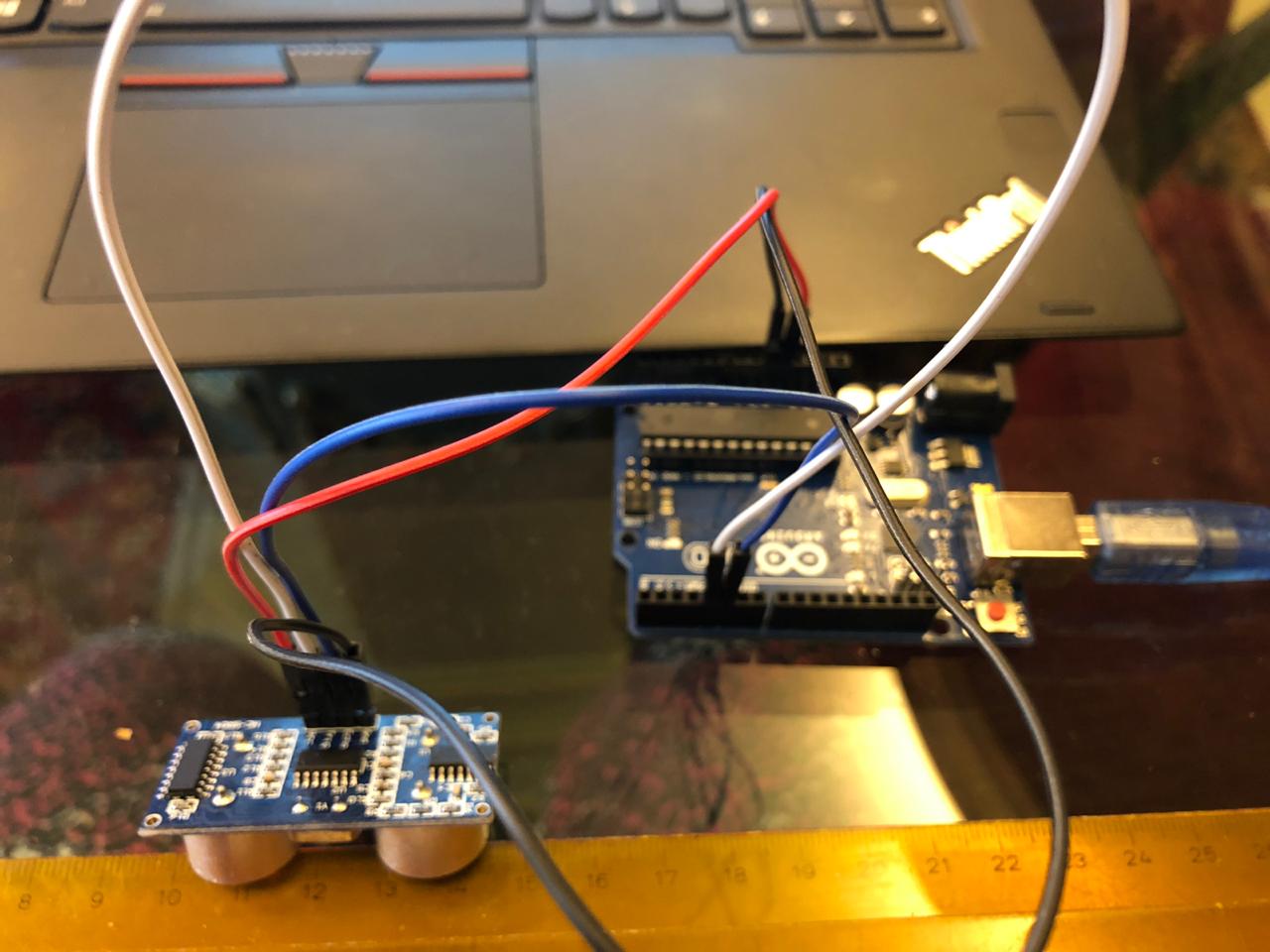
And I started to follow the steps as per the below in order to connect my Ultrasonic Sensor to the ARDUINO UNO
I found out that the Ultrasonic Sensor takes two digital pins from the ARDUINO (one for the Trig and one for the Echo) in addition to VCC and GND of course
You may look at the connections in the image below
And for the coding part, I have used the one available on the same website as per the below:
                             /*
* Ultrasonic Sensor HC-SR04 and Arduino Tutorial
*
* by Dejan Nedelkovski,
* www.HowToMechatronics.com
*
*/
// defines pins numbers
const int trigPin = 9;
const int echoPin = 10;
// defines variables
long duration;
int distance;
void setup() {
pinMode(trigPin, OUTPUT); // Sets the trigPin as an Output
pinMode(echoPin, INPUT); // Sets the echoPin as an Input
Serial.begin(9600); // Starts the serial communication
}
void loop() {
// Clears the trigPin
digitalWrite(trigPin, LOW);
delayMicroseconds(2);
// Sets the trigPin on HIGH state for 10 micro seconds
digitalWrite(trigPin, HIGH);
delayMicroseconds(10);
digitalWrite(trigPin, LOW);
// Reads the echoPin, returns the sound wave travel time in microseconds
duration = pulseIn(echoPin, HIGH);
// Calculating the distance
distance= duration*0.034/2;
// Prints the distance on the Serial Monitor
Serial.print("Distance: ");
Serial.println(distance);
}
The test can be checked in the below video:
I have watched the following youtube video to help me out
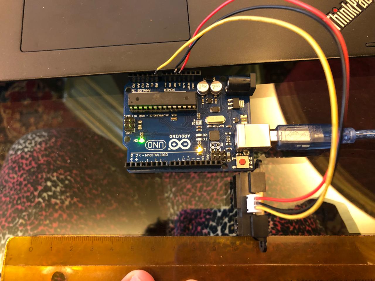
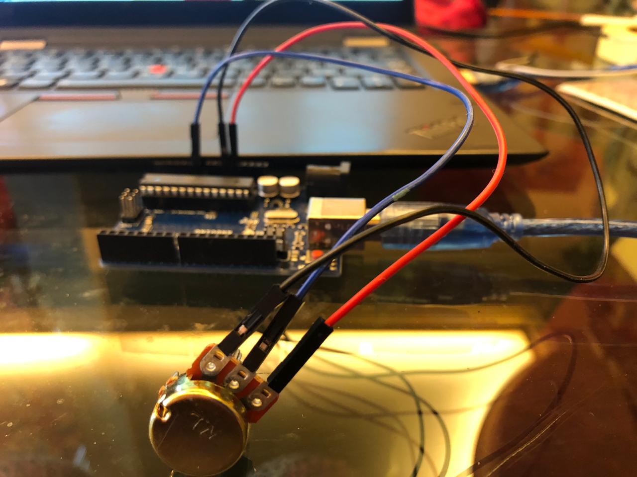
And I started to follow the steps as per the below in order to connect my potentiometer to the ARDUINO UNO
I found out that the potentiometer takes one analog pin from the ARDUINO in additiong to VCC and GND of course
You may look at the connections in the image below
And for the coding part, I have used the one available from the video on this websiteas per the below:
                             //Original source:  https://www.arduino.cc/en/Tutorial/ReadAnalogVoltage

// This code is used with a video tutorial for RoboJax.com
// Published on April 24, 2017 from Aajx, ON, Canada.
// Written/Edited by A.B.S

// This Arduino


void setup()

{

  Serial.begin(9600);          //  setup serial

}


void loop(){

  int sensorValue = analogRead(A0);
  // Convert the analog reading (which goes from 0 - 1023) to a voltage (0 - 5V):
  float voltage = sensorValue * (5.0 / 1023.0);
  // print out the value you read:
  Serial.print("Voltage =");// prins the text "Voltage ="
  Serial.print(voltage);
  Serial.println();
  delay(300);

}
The test can be checked in the below video: