networking and communication

week_13

assignment

Group assignment: Send a message between two projects.

Individual assignment: Design, build, and connect wired or wireless node(s)with network or bus addresses.

experimentation

make it happen

Group Assignment - participants:Josep Marti, Felipe Santos, Alberto Lopez, Diar Amin, Gustavo Abreu

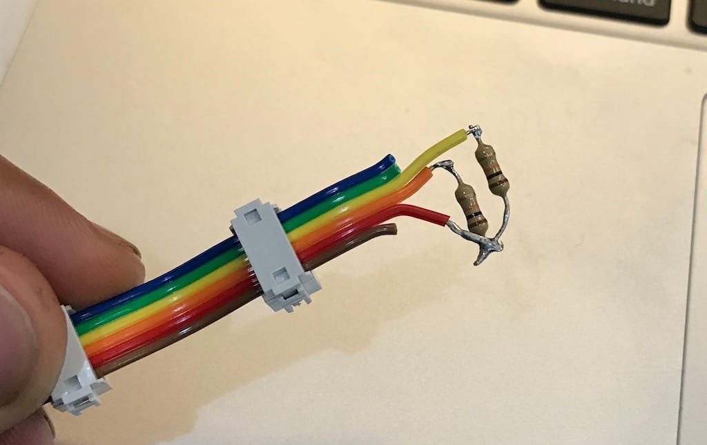
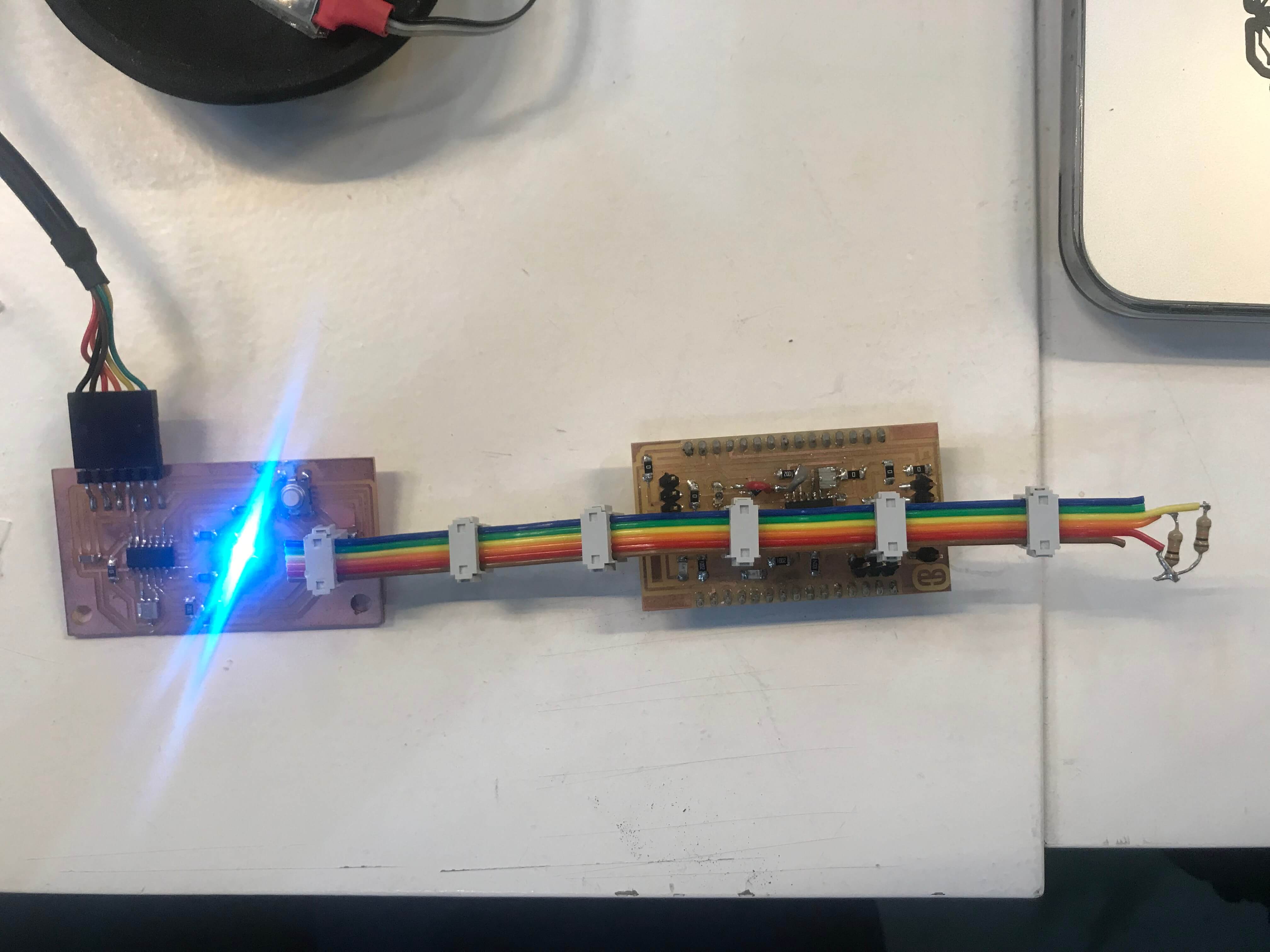
For communicating between projects, I’ve paired with Josep Marti and Diar Amin. We decided to use the ribbon cable already assembled to create an i2C hub and talk with our hello boards. For I2C to work we need two PullUp resistors, like this:

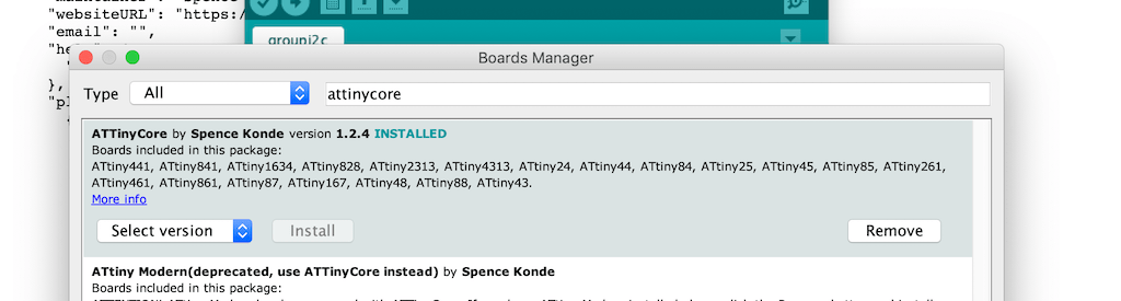
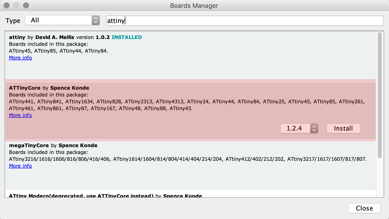
Since we’ll be using Attiny44s and it doesn’t support the Arduino wire library. The first step is to add the AttinyCore from this link to arduino, then install it on the boards manager.

By adapting Josep’s code, we managed to get all boards talking and changing the master’s color when pressing the buttons.

This is the master’s code:

#include <Wire.h> int State[] = {0, 0, 0}; int but=8; int R=7; int G=2; int B=3; int Gustavo = 1; int Diar = 2; void setup() { Wire.begin(); delay(5000); } void loop() { if (digitalRead(but)== HIGH) { analogWrite(R,255); analogWrite(G,0); analogWrite(B,255); State[0] = 1; } else { analogWrite(R,255); analogWrite(G,255); analogWrite(B,0); State[0] = 0; } readU(); writeU(); delay(10); } void readU() { Wire.requestFrom(Gustavo, 1); State[1] = Wire.read(); Wire.requestFrom(Diar, 1); State[2] = Wire.read(); } void writeU() { Wire.beginTransmission(Gustavo); Wire.write(State[2]); Wire.endTransmission(); Wire.beginTransmission(Diar); Wire.write(State[0]); Wire.endTransmission(); }

This is the slaves:

#include <Wire.h> int LED = 1; //Change it for your LED pin int But = 2; //Change it for your Button pin int Gustavo = 1; int Diar = 2; int LEDState = 0; int ButState = 0; void setup() { Wire.begin(Diar); //Change the name Wire.onReceive(receiveEvent); Wire.onRequest(requestEvent); } void loop() { if (digitalRead(But)==HIGH) { ButState = 1; } else{ ButState = 0; } if (LEDState == 1) { digitalWrite(LED, HIGH); } else { digitalWrite(LED, LOW); } } void receiveEvent() { LEDState=Wire.read(); } void requestEvent() { Wire.write(ButState); }

video demonstration of our group assignment

Individual assignment:

After I started to explore how I can make it happend with my board. First Test - so one Board (I borrowed Josephs) as a master and was adjusting everything to make work with my board for final project with ATtiny84 as a slave.

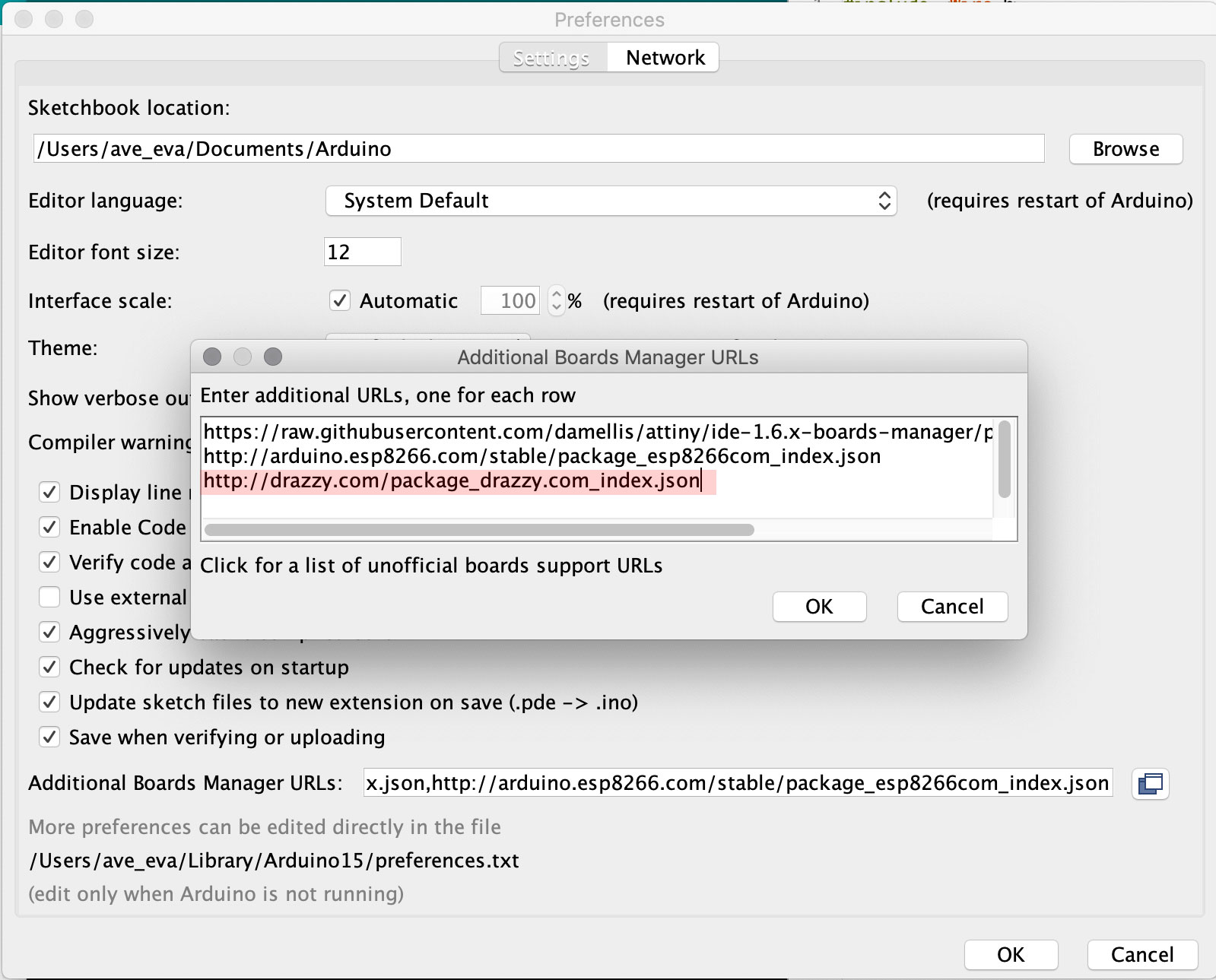
copy this link to my arduino preferences.

video demonstration

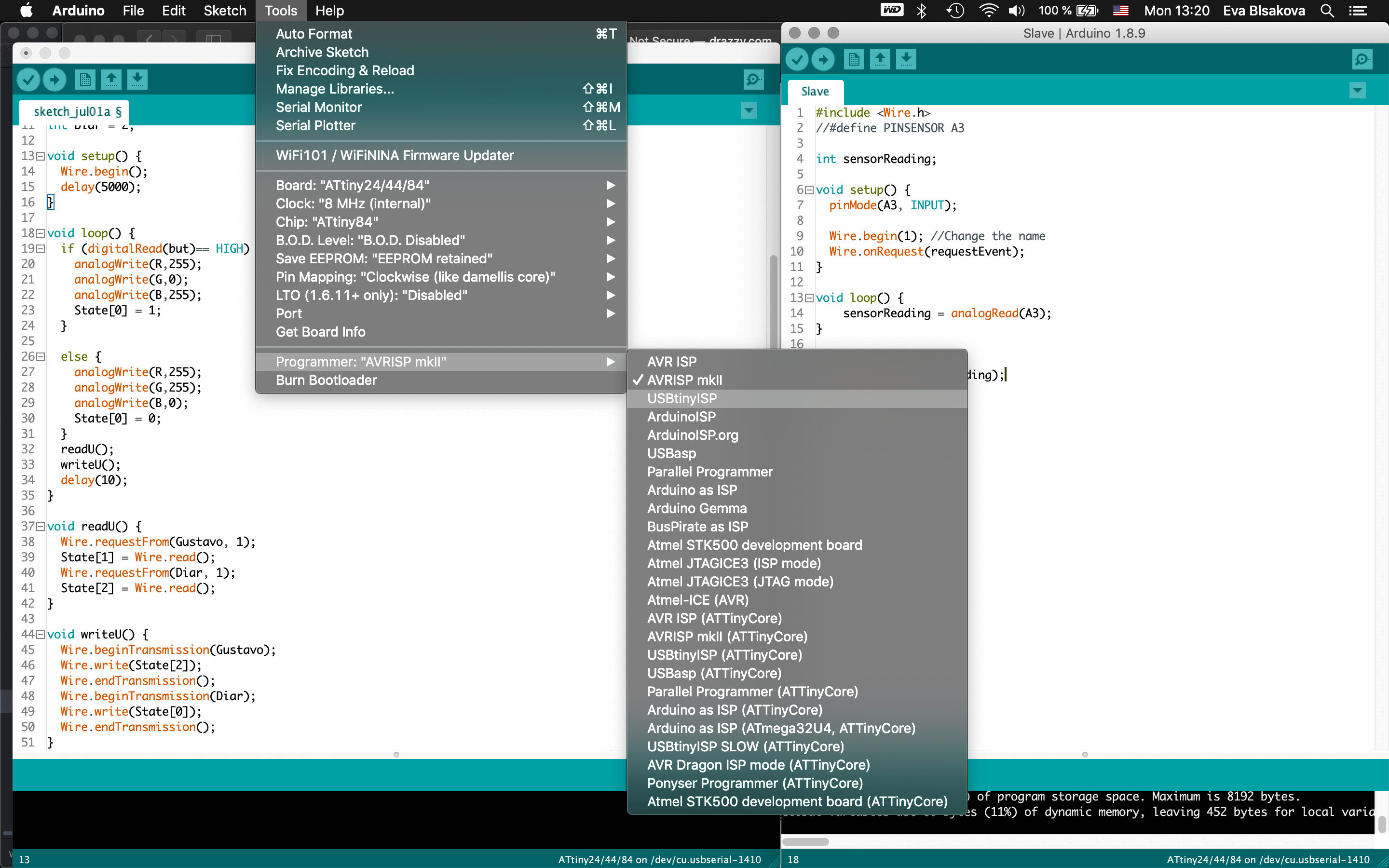
Than, next exploration with I2C communication - Instead of Josephs board, I plugged my own HelloBoard from electronics design week with ATtiny44 using it as a slave with a button for a color change communication when the button is pressed and uploaded this code to it:

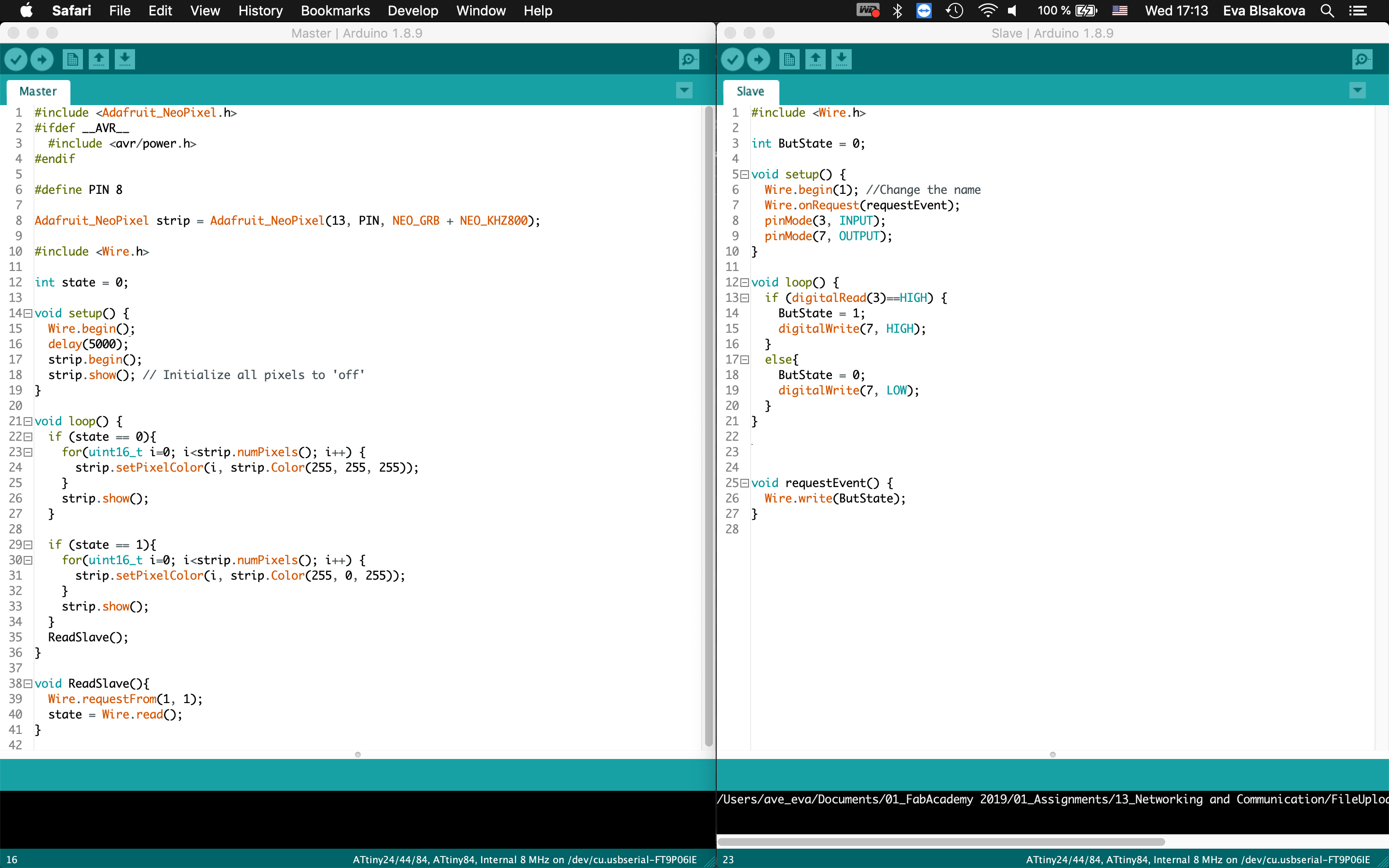
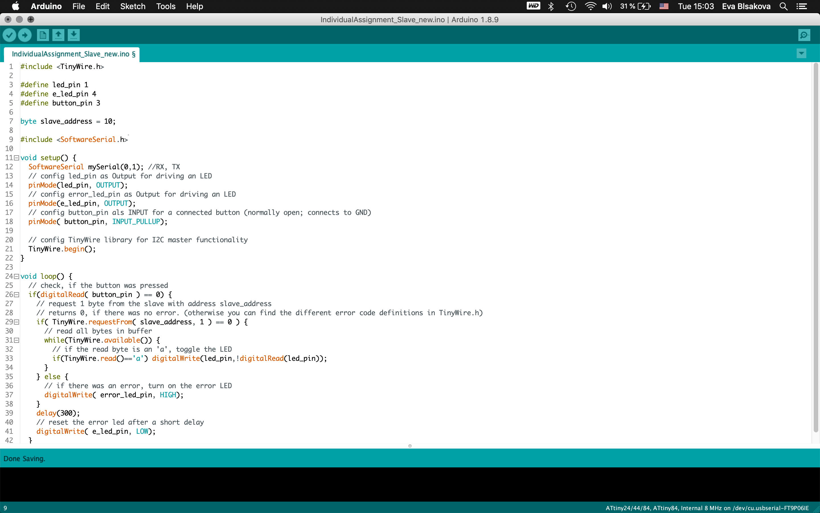
Arduino code for Slave: This code is really simple, it just reads the state of the button connected to pin 3 of the ATtiny. When the lecture is HIGH, it saves the global variable ButState as a 1 and lights up the LED connected to pin 7. Otherwise, if the button pin is LOW, it sets the ButSTate variable to 0 and turn off the LED. Then, when the master boards makes a request to the board using the address 1, the program runs the void requetEvent() where it sends the ButState variable throught the Wire.h library to the master, sending the state of the button:

#include <Wire.h> int ButState = 0; void setup() { Wire.begin(1); //Change the name Wire.onRequest(requestEvent); pinMode(3, INPUT); pinMode(7, OUTPUT); } void loop() { if (digitalRead(3)==HIGH) { ButState = 1; digitalWrite(7, HIGH); } else{ ButState = 0; digitalWrite(7, LOW); } } void requestEvent() { Wire.write(ButState); }

For Master I used my final board with Neopixels LED Strip with ATtiny84.

Arduino code for Master: The master board is programmed to light up the NeoPixels strip deppending on the valu of the state variable. This state variable is defined in the ReadSlave void that is executed during every loop of the program. This loop requests one byte to the slave with an addredd equals to 1, and reads what the slave is sending. In our case, it reads the state of the button, so, when the button is pressed it shines in one colour, when it's unpressed, it shines to a different one:

#include <Adafruit_NeoPixel.h> #ifdef __AVR__ #include <avr/power.h> #endif #define PIN 8 Adafruit_NeoPixel strip = Adafruit_NeoPixel(13, PIN, NEO_GRB + NEO_KHZ800); #include <Wire.h> int state = 0; void setup() { Wire.begin(); delay(5000); strip.begin(); strip.show(); // Initialize all pixels to 'off' } void loop() { if (state == 0){ for(uint16_t i=0; i<strip.numPixels(); i++) { strip.setPixelColor(i, strip.Color(255, 255, 255)); } strip.show(); } if (state == 1){ for(uint16_t i=0; i<strip.numPixels(); i++) { strip.setPixelColor(i, strip.Color(255, 0, 255)); } strip.show(); } ReadSlave(); } void ReadSlave(){ Wire.requestFrom(1, 1); state = Wire.read(); }

Video demonstration of light change when the button is pressed.

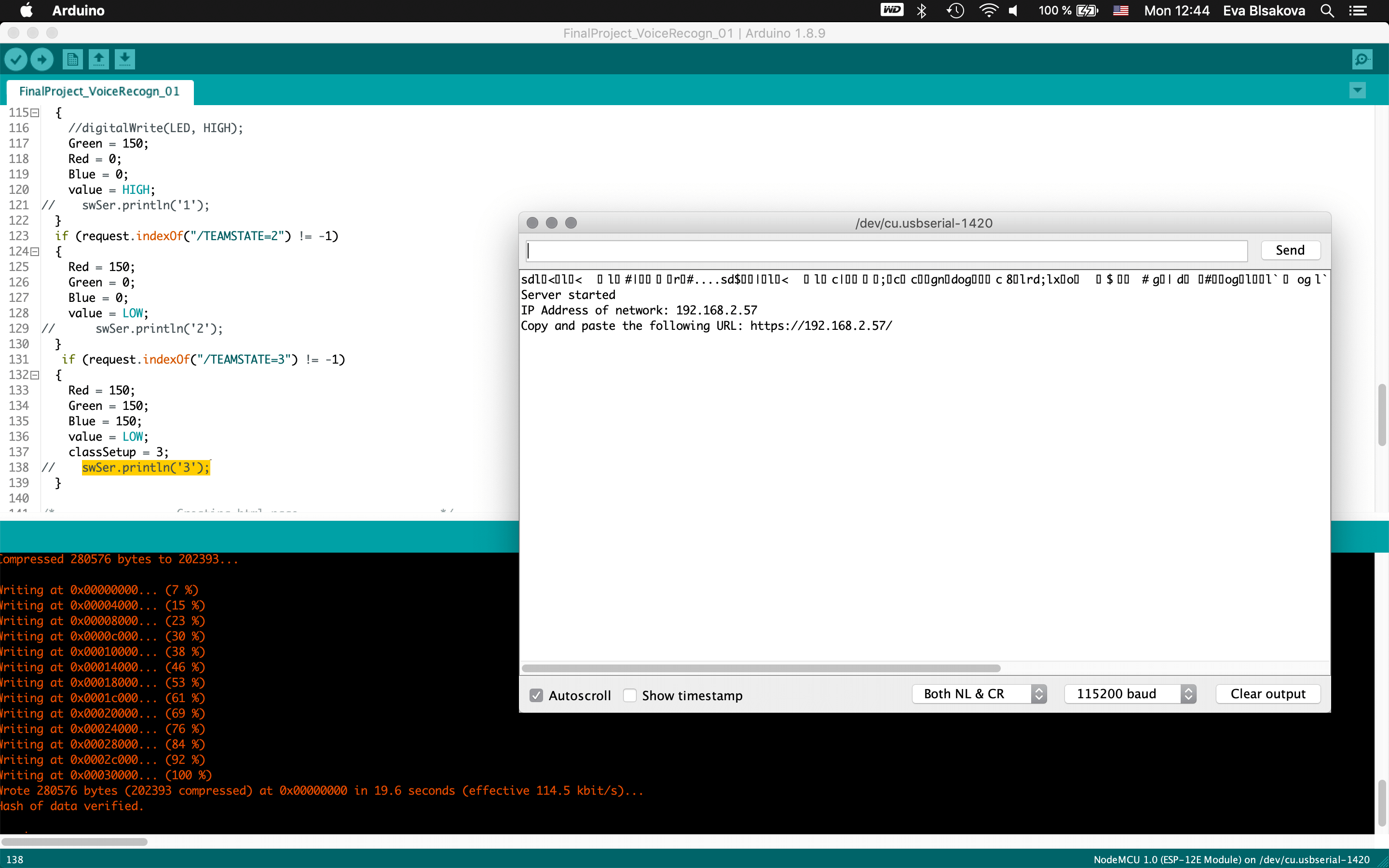
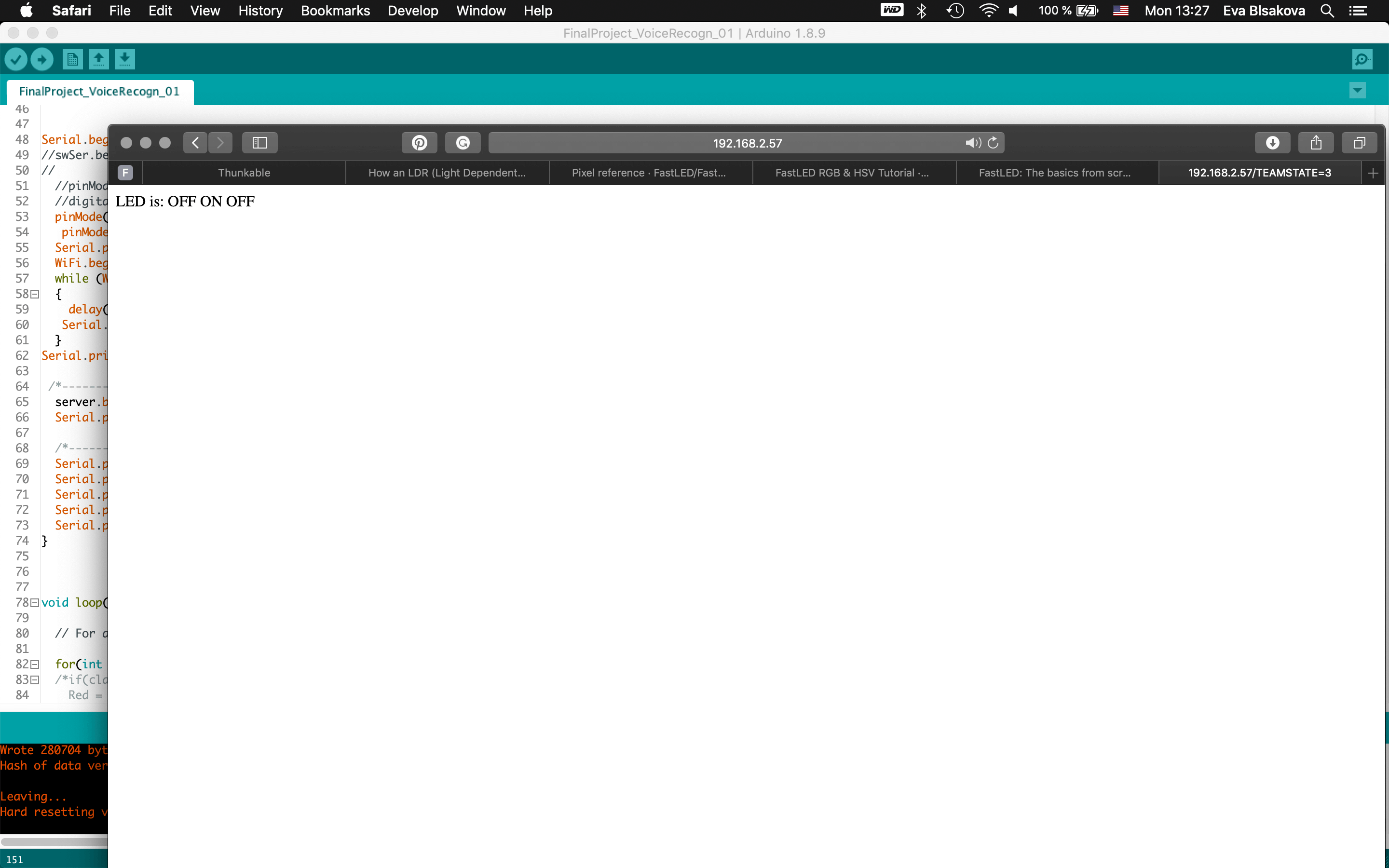
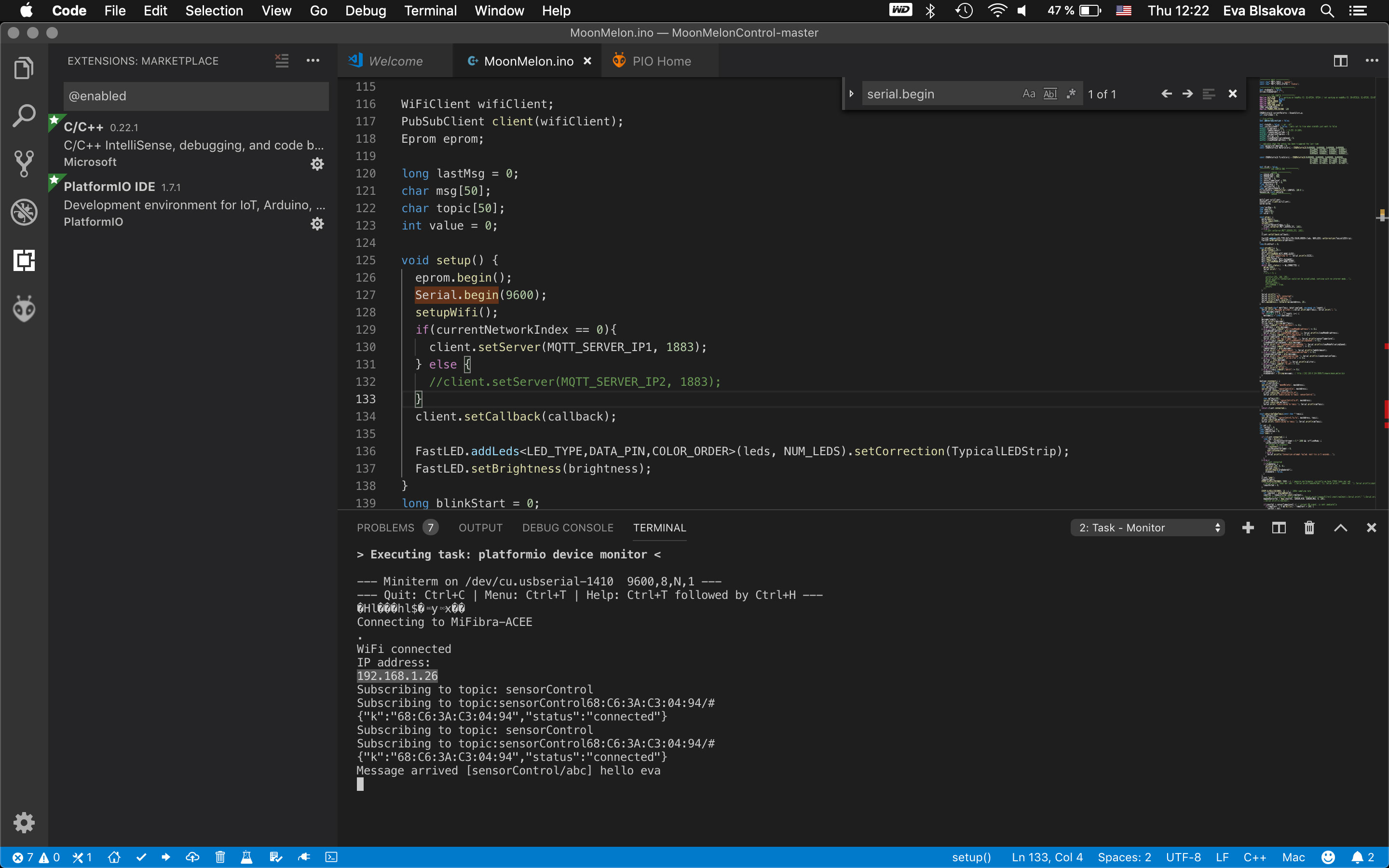
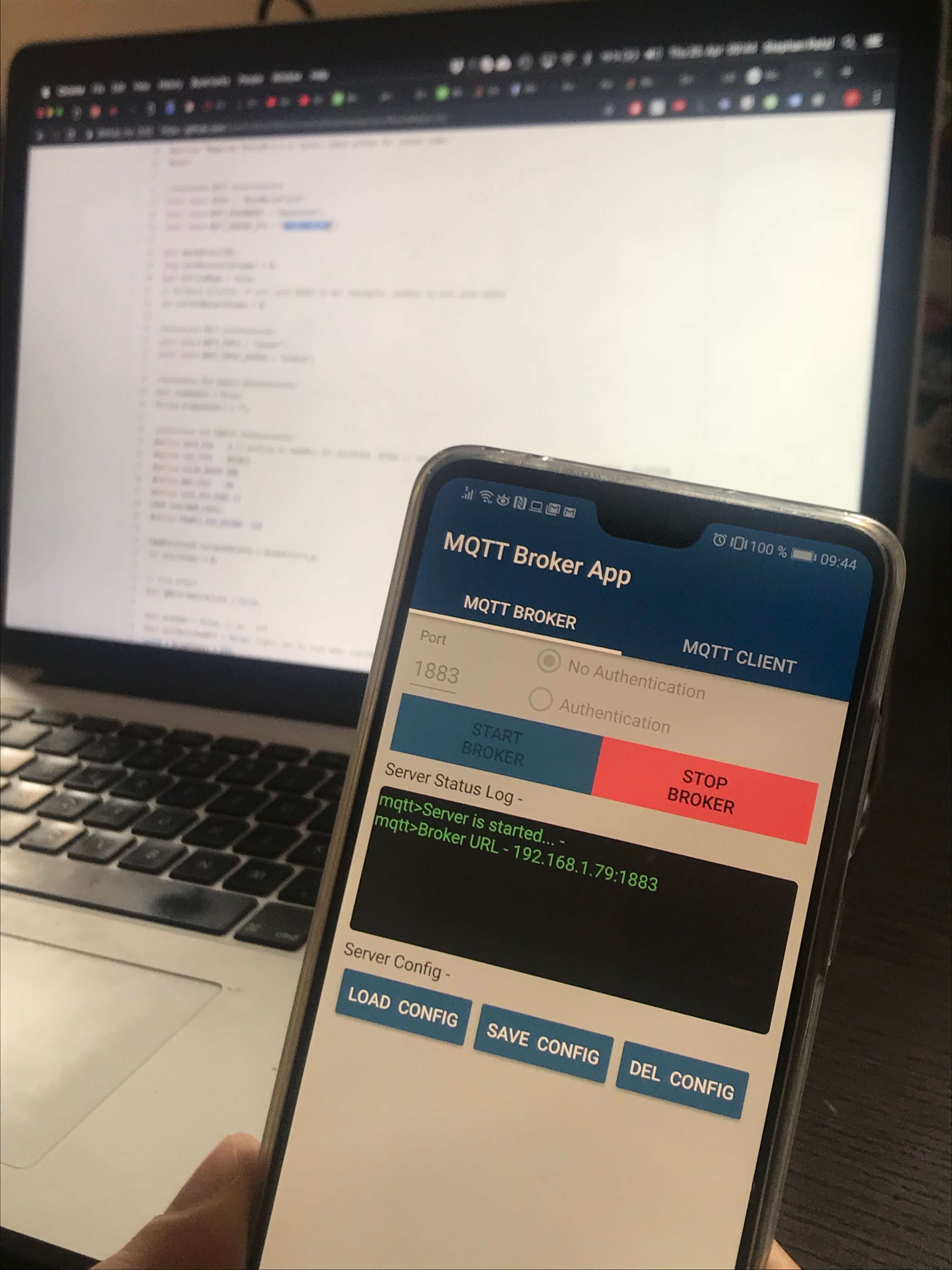
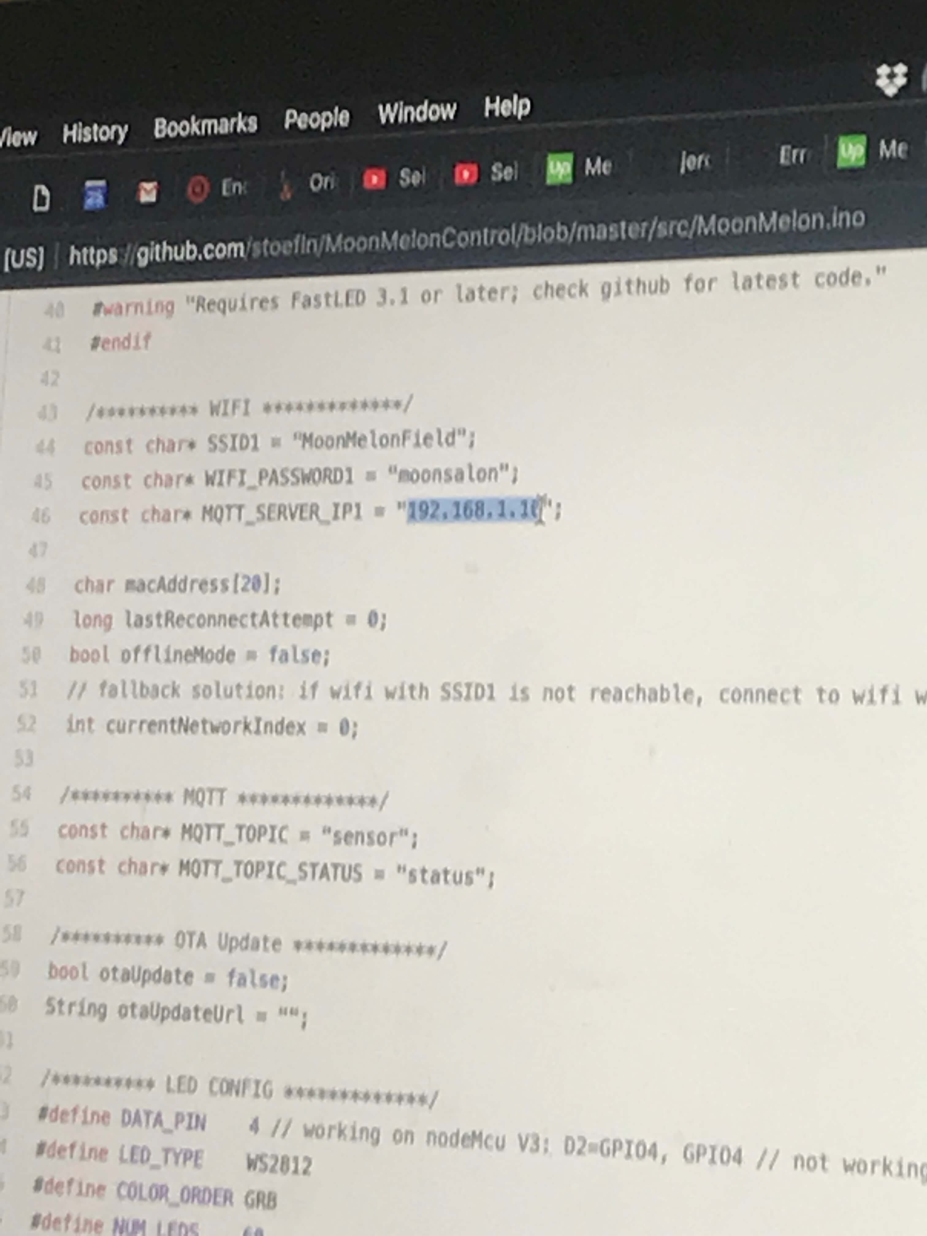
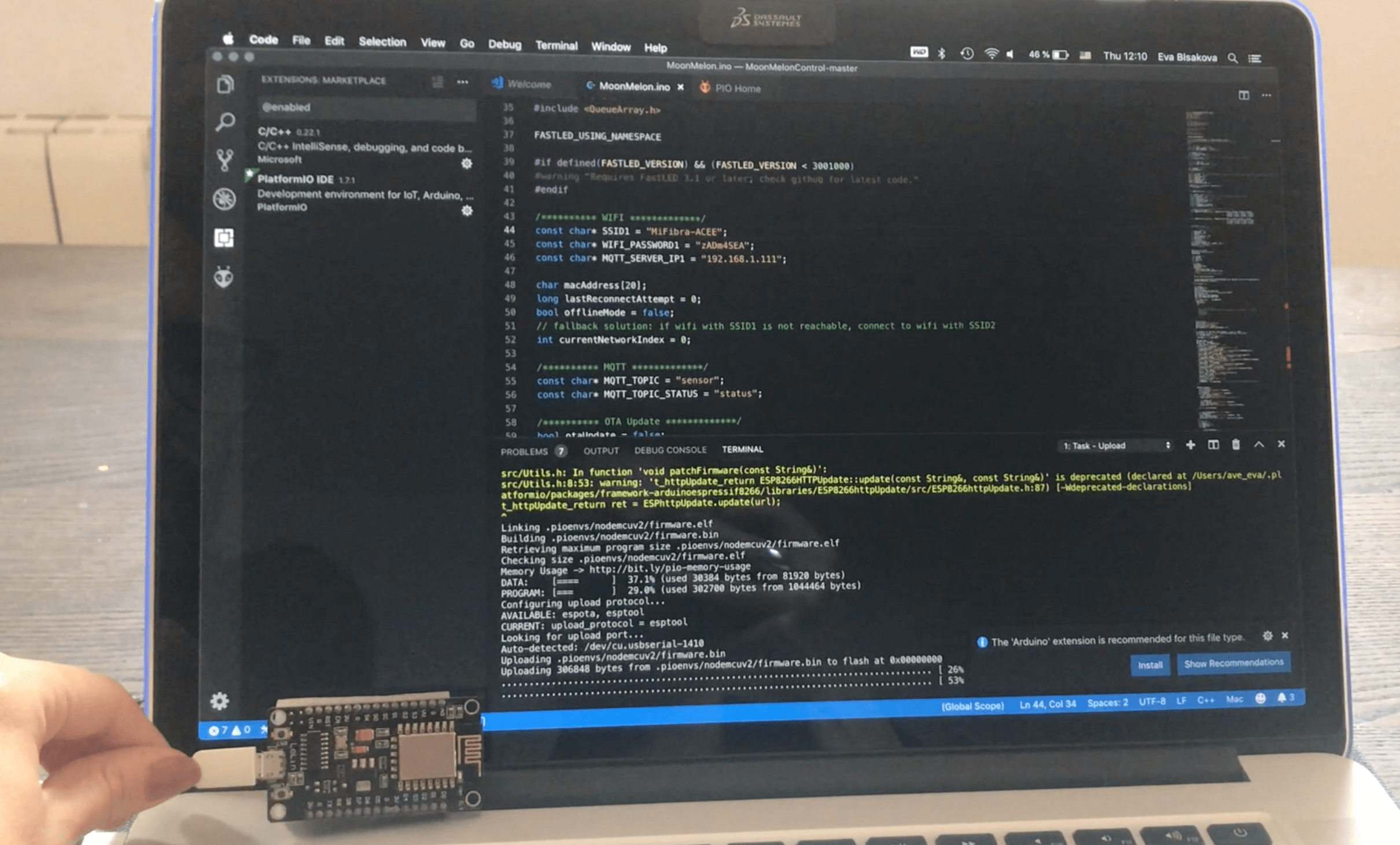
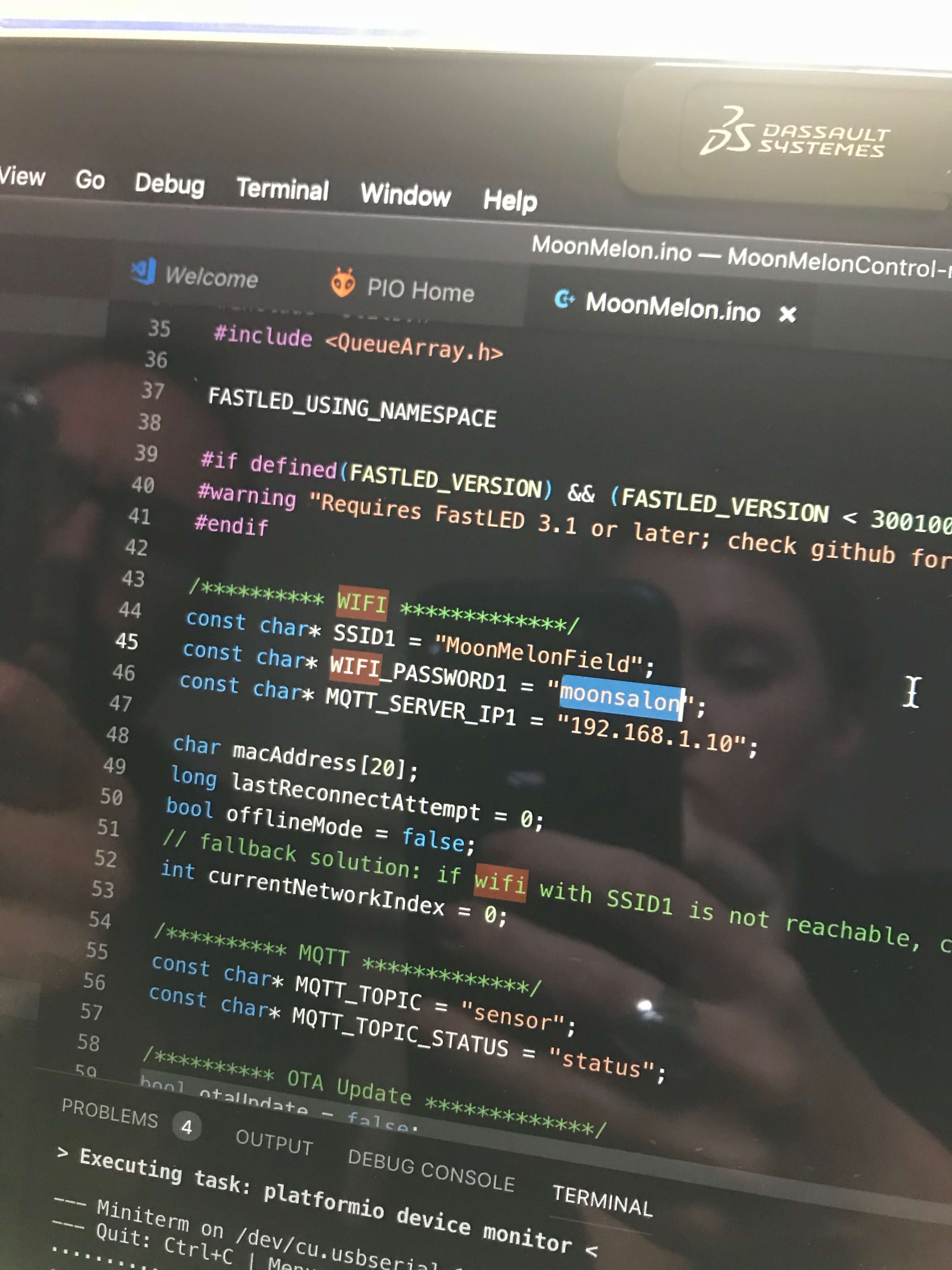
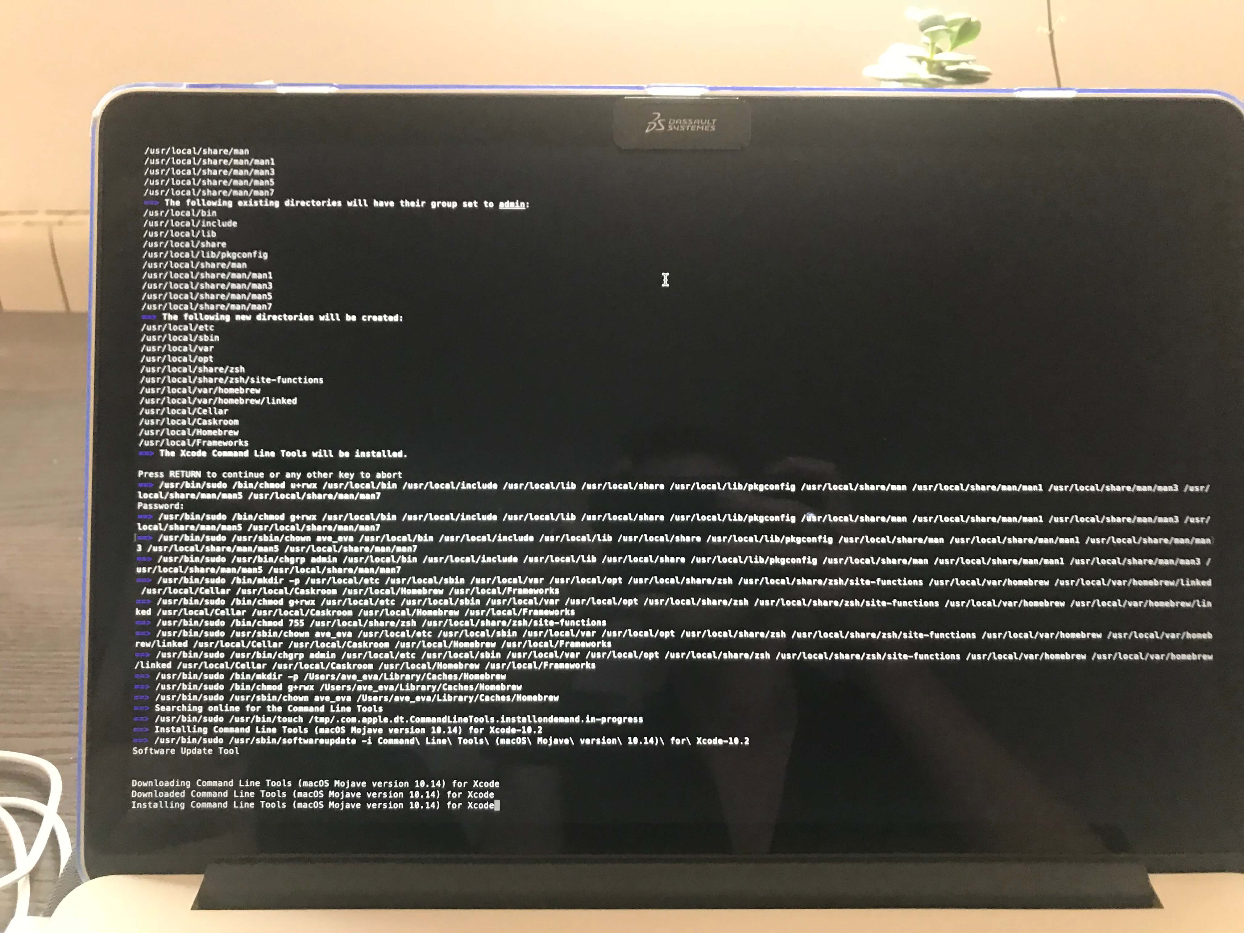
I have also experimented with board including Wifi extention to check the networking and communication possibilities:

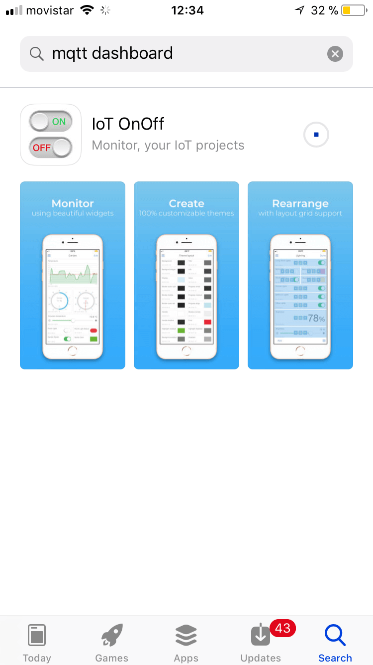
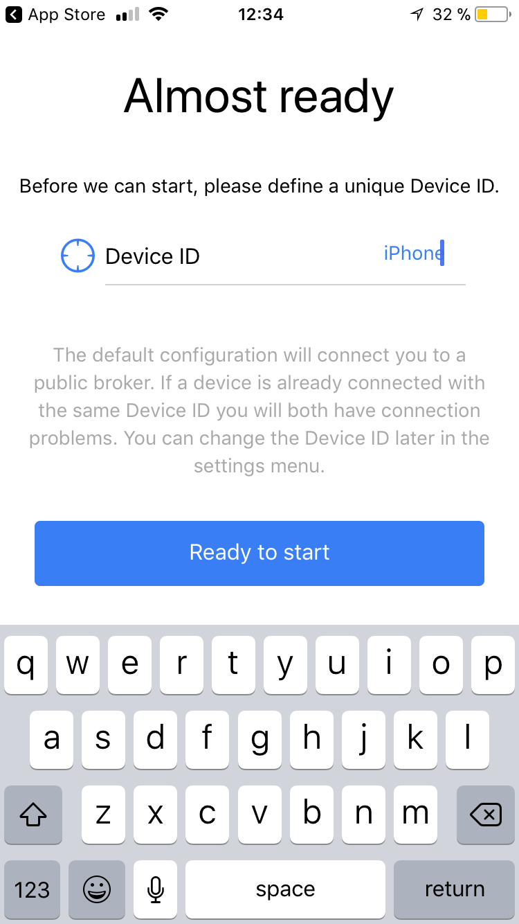
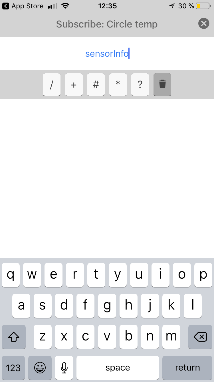
As a test I tried sending messages via MQTT using board NodeMCU V3 which has already embedded wifi component.

download files

also started to apply this weeks assignment on my final project app online creation what will be running with thunkable code.

keywords

_purposes_location_parallelism_modularity_interference_serial bus_asynchronous_I2C_SPI_CAN_USB_OSI layers: 7: application (HTTP) 6: presentation (SSL) 5: session (RPC) 4: transport (TCP, UDP) 3: network (IP) 2: data link (MAC) 1: physical (PHY)_physical media_capacity_bandwidth_wired_single-ended, differential, powerline_open collector, open drain_transmission (pass) gate, tri-state_transmission line_waveguide_TIA RS232, 422, 485_ 802.3 ethernet_chip module_SONET optical fiber_wireless_Bluetooth BLE GATT GAP UUID Services app stack_optical_transmitter receiver LiFi_acoustic_modulation_channel sharing_networking_Internet protocols_RFCs_IPv4, IPv6_DNS DHCP NAT private_UDP, TCP_HTTP_BGP AODV ROLL_sockets_Wireshark_SLIP_Internet 0_APA_RF_radios(oscillator, mixer, PA, LNA, IF, I/Q, demod, baseband, filters)_antennas(Q, antenna gain, impedance matching)_FabFi_single-chip_RN4871 (2.4 GHz Bluetooth)_chip module commands_ MicroPython JavaScript NodeMCU Lua RTOS FreeRTO_ software radio_

useful links

FabAcademy 2019_week_13