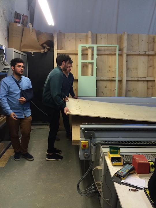
It is important to measure the full sheet from every corner. It is common to have different thickness through the material, due to fabrication or storage conditions. For instance, if the board is standing on the ground, the bottom corner may absorb humidity and be ticker.
Remember the 0 is set to the bottom left corner.
If necessary, you can remove the dust collector to make it easier to change the tool. Use the machine’s wrench and key to release the collet and holder.
For safety, don’t hold it from the flutes. You can easily cut yourself. It is recommended to hold the shank instead.
A little trick to get the collet out of the holder is to press it laterally.
You should leave around 2-3mm of the shank out of the collet and then tighten with the wrench.
If you placed the board aligned with the machine bed, X,Y could be set by sending it to home, if not, move then to the origin of your board and set the 0 there.
To set Z, we have the auto-leveler, that should be set right under the tool.
After doing all that, is time to start the machine, but first, a couple of checks:
Only then, start the job.
Finish Job
After finishing, move the axis away so you can reach the cutout pieces, turn off the machine and dust collector, only then proceed to remove the material. Remembering to clean after yourself and store all the tools and protection gear.
Chip load Calculation
A really basic calculation:
Feed Rate = Number of Flutes x RPM x Chip Load
We got 2440x1220 15mm spruce plywood boards. After a quick search, we found that the chip load is between .011"-.013". Since our machine is set up in millimeters, we did the following calculations
Tests
Even tough we had the numbers, we wanted to try the possible combinations, varying from 18k RPM with 2k feed rate, up to 24k RPM with 7000 feed rate.
But, the math does not lie. The best results were the ones we previously calculated. This are the results with a downcut end mill.
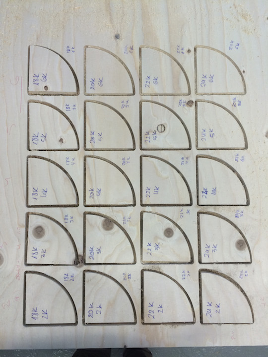
We repeated the test with a up cut as well and got batter results. But probably the main reason is because the tool was newer and more sharp.
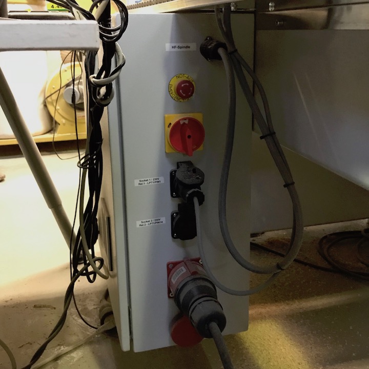
Turn on machine
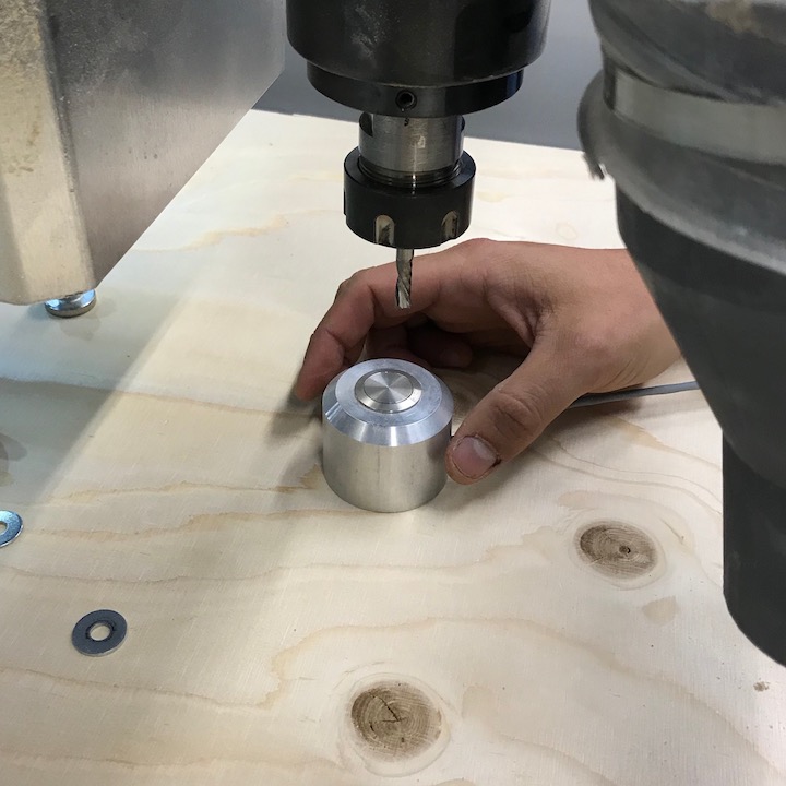
To set origin
Place the button device and move the mill till center of button. Then check pressing with the mill tip if it hits the center to set the 0 position.
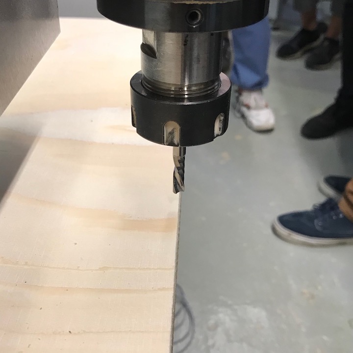
Align mill to border to set x axis.
Do same for y axis.
Set again the the dust collector.
Load screws file on pc, put on glasses, turn on vacuum, Start:
Machine
Z align
X align
Y align
Ready
Test Cut
pass 1 2000 18000 smell burned wood and making dust
pass 11 2k 22k turned air off to prevent fire
https://www.wisaplywood.com/products/about-plywood/appearance-of-spruce-plywood/
Grade III
A grade which may have open splits and knot holes according to EN635-3. Grade III offers the full technical strength of spruce plywood and it is recommended for use in applications where surface appearance is not of primary importance. Grade specification according to EN 635-5.
https://www.guhdo.com/chipload-calculator
Plywood 1/4" tool .011"-.013" (0.28mm - 0.33mm)
RPM x Flutes X chip load
18k x 1 x 0.28 5040
18k x 1 x 0.33 5940
20k x 1 x 0.28 5600
20k x 1 x 0.33 6600
22k x 1 x 0.28 6160
22k x 1 x 0.33 7260
24k x 1 x 0.28 6720
24k x 1 x 0.33 7920
Even in a hurry is recommended to use up to 70% of the flute length, otherwise there might be the hazzard of breaking the tool or significantly reducing the lifespan of the tool, the so if you cut deeper, reduce feedrate and mantain or increase rpm.
Individual Assignment
The inspiration for my idea came from a former exercise, a stool with flexible seat plate, from
Javier Albo Guijarro at FabAcademy Barcelona 2018.

I used Autodesk Fusion 360 to make the design of the pattern, and imported the files later into Rhinoceros. Here, I generated the G-code for the CNC machine.
Instead of a stool, I wanted to design a booster seat for children. So my intention was to design a seat with smooth curves and avoid sharp edges. Therefore I had to create a complete new design for this "press fit" construction.
The material was a spruce Plywood board, measuring 2440 x 1220 x 15 mm, which was the same type and size we used in the group asssignment.
Designing with Fusion 360
Before I started drawing a sketch, I first had to measure the seat of the chair, where the booster seat is going to be placed. I mearsured the height of the table and calculated the distance between table and seat, to make sure that there is enough space for the legs. Calculating all together I finally had the frame dimensions for the booster seat and started to sketch the basic form of the layers.

Then I added the "living hindge" to the layer, but in an reduced version regarding Javier's stool model. In my case the distance between the seat level and base plate is smaller, only 3 lines fit into this space.

To improve the stability, the lateral layers were made without Living Hinge, these layers otherwise might break out to the sides. I added two holes to each layer, that's where the joints of the base plate get through.

Then I designed an other component, the base plate, on which I placed the holes for all 24 inner layers plus 2 lateral.

For the long sides of the plate I made two trims, that should stabilize the construction.

Here I sketched two joints on each short side...

... and added a fitting wedge, that fixes the joint.

The pattern tool from Fusion 360 allows to duplicate the holes and distributed them symetrically along the base plate.
These are the joints, where the 12 inside layers are going to be fixed.

Then I repeated with this tool to make the holes the opposite 12 layers. All together the booster seat has 24 layers, with two different, alternating joint positions.

Setup with Rhinoceros
After the design was finished, I exported the DXF file and opened it in Rhinoceros. Then I set the dimensions of the Plywood as shown here in the image. The starting point should be on the top surface, as it was recommended by the instructors.

To avoid unnecessary waste of material, I had to do the Nesting and optimize the distribution of the patterns on the work area.

Then I made the virtual test run in Rhino, which indicates calculation errors. Here in my case, the calculation did not accept the kerf the distance between two living hinge lines. The kerf of the mill was virtually too thick, even though every parts were set in the same way. Somehow, the program is calculating it like this, ...

... so I had to widen the distance by 0,1 mm and run the test again. This time it was accepted, the design was ready to get milled in real.
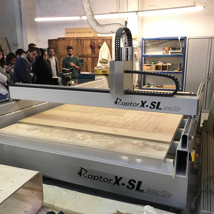
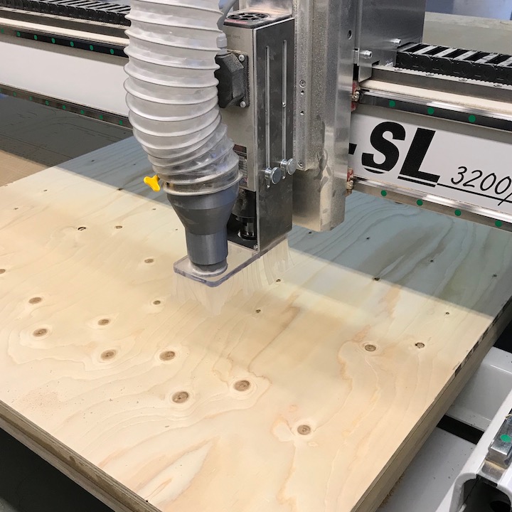
CNC Milling with Raptor X-SL 3200/S20
First I made up the settings for this machine job and used the same coordinates as before:
- End mill: 6mm single flute flat down cut
- Spindle RPM: 18.000
- Feed rate: 5.000mm/min

Just in case, I saved the setting as a custom setup.

After all settings were done, we made the test cut. Then we decided to change the spindle speed and feed rate. Considering also the milling sound, we thought that the cutting could be better:

When I started to run the job, the mill was already cutting before reaching the actual starting point. I stopped the job and found out, that the plywood board was not well fixed, so that a vaulted part was higher and has been cut therefore. I fixed this part with an other screw and made sure, that it was not in the line of the milling paths.

Then I ran the machine again and this milling was good.

To take out the pieces, I had to breack the 'jumpers' with a flat screw driver and a hammer. At the beginning it wasn't so easy to find them, but figuered out their spots.

While I was assembeling he pieces, they didn't fit well. I only calculated 0,1 mm offset for each side of the holes, because I wanted to make sure, that the press fit sick well, but this was obviously not enough. So I had to sand quite a lot to make them fit into their holes.

Finally I had to force it a little bit. From that two little pieces from the bottom broke out, but was almost irrelevant to the construction's stability.

Assignment completed:

Conclusion
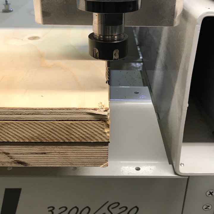
The milling technique opens a wide field for creative works. Working with this machine was a very instructive experience. The fabrication worked out without any remarkable complication. We found out, that the Plywood we used, gets slightly frayed at it's cutten borders. For that, to optimize the milling job, it's recommandable to adjust well it's dimensions, especially for the fabrication of finger joints.
Download Files:
Computer-Controlled Machining
Group Assignment
Class Week 7
This week's task had to be done with the Raptor X-SL 3200/S20 CNC Milling machine:
Measure and fix material
It is important to measure the full sheet from every corner. It is common to have different thickness through the material, due to fabrication or storage conditions. For instance, if the board is standing on the ground, the bottom corner may absorb humidity and be ticker.
Remember the 0 is set to the bottom left corner.
Install end mill
If necessary, you can remove the dust collector to make it easier to change the tool. Use the machine’s wrench and key to release the collet and holder.
For safety, don’t hold it from the flutes. You can easily cut yourself. It is recommended to hold the shank instead.
A little trick to get the collet out of the holder is to press it laterally.
You should leave around 2-3mm of the shank out of the collet and then tighten with the wrench.
Set each axis origin
On this machine, we use KinetiC CNC Control in order to open the export file.
If you placed the board aligned with the machine bed, X,Y could be set by sending it to home, if not, move then to the origin of your board and set the 0 there.
To set Z, we have the auto-leveler, that should be set right under the tool.
Start Job
After doing all that, is time to start the machine, but first, a couple of checks:
Finish Job
After finishing, move the axis away so you can reach the cutout pieces, turn off the machine and dust collector, only then proceed to remove the material. Remembering to clean after yourself and store all the tools and protection gear.
Chip load Calculation
A really basic calculation:
Feed Rate = Number of Flutes x RPM x Chip Load
We got 2440x1220 15mm spruce plywood boards. After a quick search, we found that the chip load is between .011"-.013". Since our machine is set up in millimeters, we did the following calculations
18k x 1 x 0.28 5040
20k x 1 x 0.28 5600
22k x 1 x 0.28 6160
24k x 1 x 0.28 6720
Tests
Even tough we had the numbers, we wanted to try the possible combinations, varying from 18k RPM with 2k feed rate, up to 24k RPM with 7000 feed rate.
But, the math does not lie. The best results were the ones we previously calculated. This are the results with a downcut end mill.
We repeated the test with a up cut as well and got batter results. But probably the main reason is because the tool was newer and more sharp.
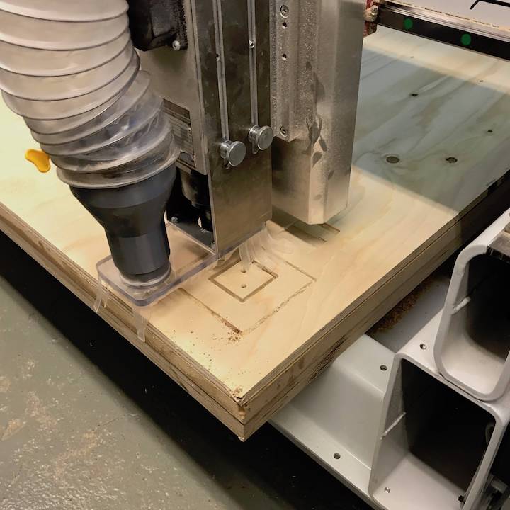
Turn on machine
To set origin
Place the button device and move the mill till center of button. Then check pressing with the mill tip if it hits the center to set the 0 position.
Align mill to border to set x axis.
Do same for y axis.
Set again the the dust collector. Load screws file on pc, put on glasses, turn on vacuum, Start:
Machine
Z align
X align
Y align
Ready
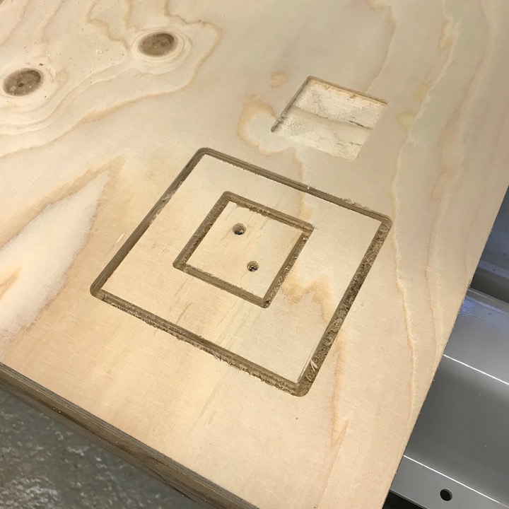
Test Cut
pass 1 2000 18000 smell burned wood and making dust
pass 11 2k 22k turned air off to prevent fire
https://www.wisaplywood.com/products/about-plywood/appearance-of-spruce-plywood/
Grade III
A grade which may have open splits and knot holes according to EN635-3. Grade III offers the full technical strength of spruce plywood and it is recommended for use in applications where surface appearance is not of primary importance. Grade specification according to EN 635-5.
https://www.guhdo.com/chipload-calculator
Plywood 1/4" tool .011"-.013" (0.28mm - 0.33mm)
RPM x Flutes X chip load
18k x 1 x 0.28 5040
18k x 1 x 0.33 5940
20k x 1 x 0.28 5600
20k x 1 x 0.33 6600
22k x 1 x 0.28 6160
22k x 1 x 0.33 7260
24k x 1 x 0.28 6720
24k x 1 x 0.33 7920
Even in a hurry is recommended to use up to 70% of the flute length, otherwise there might be the hazzard of breaking the tool or significantly reducing the lifespan of the tool, the so if you cut deeper, reduce feedrate and mantain or increase rpm.
Individual Assignment
The inspiration for my idea came from a former exercise, a stool with flexible seat plate, from Javier Albo Guijarro at FabAcademy Barcelona 2018.

I used Autodesk Fusion 360 to make the design of the pattern, and imported the files later into Rhinoceros. Here, I generated the G-code for the CNC machine.Instead of a stool, I wanted to design a booster seat for children. So my intention was to design a seat with smooth curves and avoid sharp edges. Therefore I had to create a complete new design for this "press fit" construction.
The material was a spruce Plywood board, measuring 2440 x 1220 x 15 mm, which was the same type and size we used in the group asssignment.
Designing with Fusion 360
Before I started drawing a sketch, I first had to measure the seat of the chair, where the booster seat is going to be placed. I mearsured the height of the table and calculated the distance between table and seat, to make sure that there is enough space for the legs. Calculating all together I finally had the frame dimensions for the booster seat and started to sketch the basic form of the layers.
Then I added the "living hindge" to the layer, but in an reduced version regarding Javier's stool model. In my case the distance between the seat level and base plate is smaller, only 3 lines fit into this space.
To improve the stability, the lateral layers were made without Living Hinge, these layers otherwise might break out to the sides. I added two holes to each layer, that's where the joints of the base plate get through.
Then I designed an other component, the base plate, on which I placed the holes for all 24 inner layers plus 2 lateral.
For the long sides of the plate I made two trims, that should stabilize the construction.
Here I sketched two joints on each short side...
... and added a fitting wedge, that fixes the joint.
The pattern tool from Fusion 360 allows to duplicate the holes and distributed them symetrically along the base plate. These are the joints, where the 12 inside layers are going to be fixed.
Then I repeated with this tool to make the holes the opposite 12 layers. All together the booster seat has 24 layers, with two different, alternating joint positions.
Setup with Rhinoceros
After the design was finished, I exported the DXF file and opened it in Rhinoceros. Then I set the dimensions of the Plywood as shown here in the image. The starting point should be on the top surface, as it was recommended by the instructors.
To avoid unnecessary waste of material, I had to do the Nesting and optimize the distribution of the patterns on the work area.
Then I made the virtual test run in Rhino, which indicates calculation errors. Here in my case, the calculation did not accept the kerf the distance between two living hinge lines. The kerf of the mill was virtually too thick, even though every parts were set in the same way. Somehow, the program is calculating it like this, ...
... so I had to widen the distance by 0,1 mm and run the test again. This time it was accepted, the design was ready to get milled in real.
CNC Milling with Raptor X-SL 3200/S20
First I made up the settings for this machine job and used the same coordinates as before:
Just in case, I saved the setting as a custom setup.
After all settings were done, we made the test cut. Then we decided to change the spindle speed and feed rate. Considering also the milling sound, we thought that the cutting could be better:
When I started to run the job, the mill was already cutting before reaching the actual starting point. I stopped the job and found out, that the plywood board was not well fixed, so that a vaulted part was higher and has been cut therefore. I fixed this part with an other screw and made sure, that it was not in the line of the milling paths.
Then I ran the machine again and this milling was good.
To take out the pieces, I had to breack the 'jumpers' with a flat screw driver and a hammer. At the beginning it wasn't so easy to find them, but figuered out their spots.
While I was assembeling he pieces, they didn't fit well. I only calculated 0,1 mm offset for each side of the holes, because I wanted to make sure, that the press fit sick well, but this was obviously not enough. So I had to sand quite a lot to make them fit into their holes.
Finally I had to force it a little bit. From that two little pieces from the bottom broke out, but was almost irrelevant to the construction's stability.
Assignment completed:
Conclusion
The milling technique opens a wide field for creative works. Working with this machine was a very instructive experience. The fabrication worked out without any remarkable complication. We found out, that the Plywood we used, gets slightly frayed at it's cutten borders. For that, to optimize the milling job, it's recommandable to adjust well it's dimensions, especially for the fabrication of finger joints.
Download Files: