
7.1. Group Assignment
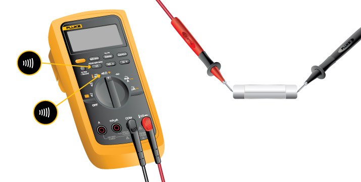
For the group assignment, we first needed to get used to all tools and components' location. But one of the most important devices in the lab was the multimeter indeed, as it became the best tool for testing the connectivity among circuits and components' continuity. This would determine whether we could keep programming and using the boards after soldering, or soldering all back again.
The only thing to do is setting the multimeter's wheel on resistance mode (Ω) and the sound option turned on, and check between both cable leads by touching if there is a beep sound. Then placing each of the wires' lead to the path on which we want to check connectivity (eg. between two VCC connections, two GND,...). When we hear the beep, this means there's connectivity, so if we need it, that is fine, but otherwise it would mean a shortcut.
7.2. Individual Assignment
For this assignment, I am focused on working with the Echo-Hello World Board model.
7.2.1. Echo-Hello Board
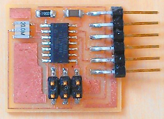
This board uses an ATTiny44 microcontroller, an FTDI connector, a 6-pin ISP Header, two 10kohms resistors, a 20MHz resonator and a 1uF capacitor. For the assignment I should add a button and an LED to program the board and check the circuit (this will need a 499ohm resistor too).
Echo-Hello world board's components and functions:
- ATTinny44 microcontroller: This high performance, low power AVR 8-bit microcontroller is perfect for simple boards. The CPU must be able to access memories, perform calculations, control peripherals, and handle interrupts. The on chip ISP Flash allows the Program memory to be re-programmed in-system through an SPI serial interface most commonly. The ATtiny44A is supported with a full suite of program and system development tools including:C Compilers, Macro Assemblers, Program Debugger/Simulators and Evaluation kits.(datasheet)(Eagle name: ATTINY44-SSU, Library: Fab).
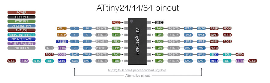
ATtiny44A pinout scheme.
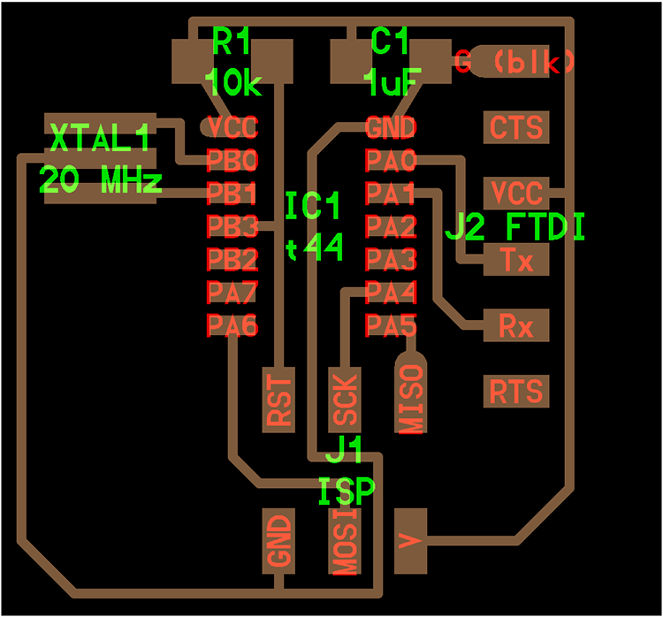
What I can get from the datasheet's pinout is that VCC and GND pins will be linked to the FTDI connector (powered to 5V), the external crystal (20MHz) will be connected to GND and Arduino pins 9 and 10, the LED will be linked to pin 7, the button to the pin 3, the TX and RX FTDI communication pins to the 0 and 1 pins; and the ISP connector to the 9 (RST), 6 (MOSI), 5 (MISO), 4 (SCK), plus the VCC and GND.
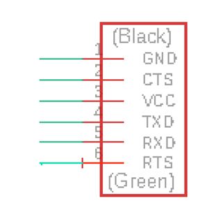
- FTDI connector: Powers the board and allows board to talk with the computer. (Eagle name: 1X06_SMD_MALE, Library:Sparkfun Connectors)
- 6-pin ISP Header: Used to program the board with the FabISP board. (Eagle name: 2X3_SMD, Library: Sparkfun Connectors)
- 10kohms resistor (x2): Used for regulating the current between components. (Eagle name: R1206, Library: Resistors, Capacitors, Inductors)
- 20MHz resonator: Used for calculating the time via frequency, more accurate than a crystal. (Eagle name: RESONATOR, Library: Fab)
- 1uF capacitor: Used for storing electric charge, to prevent from current peaks, useful between microcontroller and FTDI connector. (Eagle name: C1206, Library: Resistors, Capacitors, Inductors)
Extra components for the assignment:
- LED 1206 smd: A yellow/green LED to test if the current is flowing along the circuit and to test some easy examples. The side with the green line on the edge defines the cathode (-) which should be connected to ground (GND). (Eagle name: LED1206, Library: fab).
- Switch button: Used to cut the current of the LED. (Eagle name: 6MM_SWITCH, Library: fab).
- 499ohms resistor: Used for regulating the current through the LED circuit.
Components for programming the board:
- FTDI header-USB cable: Used to power the board with the computer through USB.
- Switch button: Used to program the board with the FabISP board. (Eagle name: 2X3_SMD, Library: Sparkfun Connectors)
7.2.2. PCB design
I will design a PCB taking the 'Hello World Board' as a reference. Work with Eagle. Download FAB components Library.
First you need to open both 'Schematic' and 'Board' windows on Eagle to work on. Then search and place the components on 'schematics'.
Add the paths with the green paths layer.
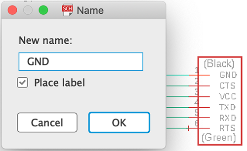
Then add labels to each component connection.
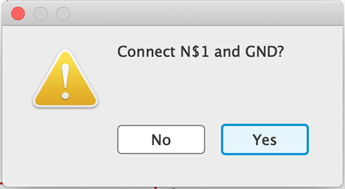
When the software detects same label in different components, then approve the connection.
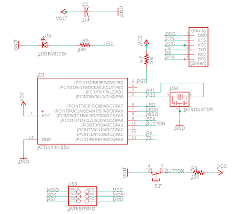
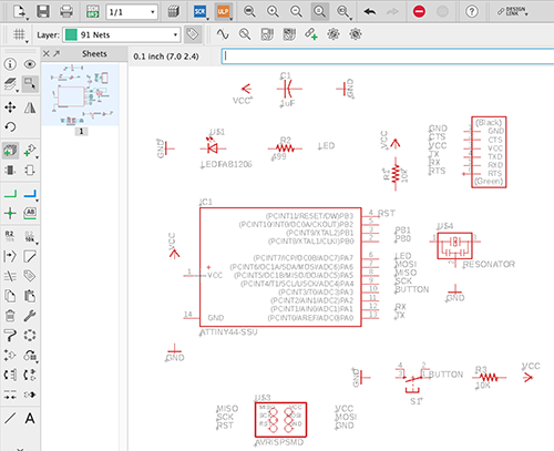
The components map should appear like this on 'Schematic' window.
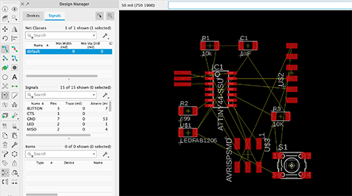
Then when you switch to 'Board' window, the elemnts should show up like this.
Add the connections between components in 'Board', replacing the automatic paths in yellow.
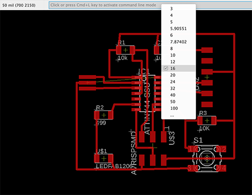
To adapt the line size, select all components and write 'Cha wid' on the command line to change the size of all lines in one.
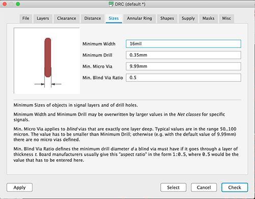
Then change the milling size on DRC properties.
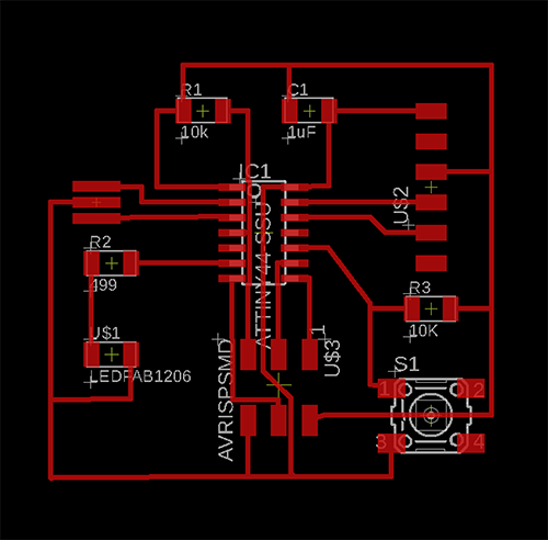
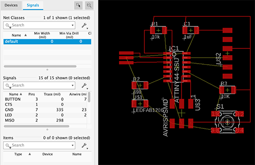
Once reordered all the elements, the Board map should be like this.
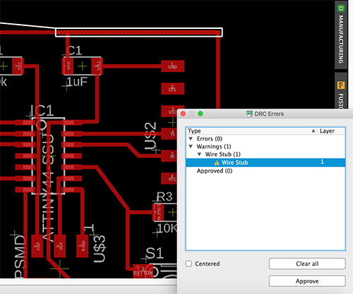
To check all the connections and line properties, the DRC Check should be run.
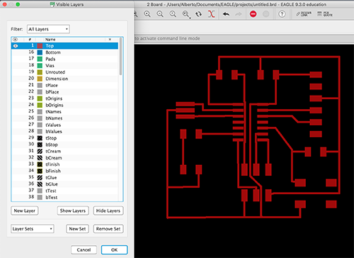
Hide all layers that should not appear on the .png image to be milled. Only show 'Top Layer'.
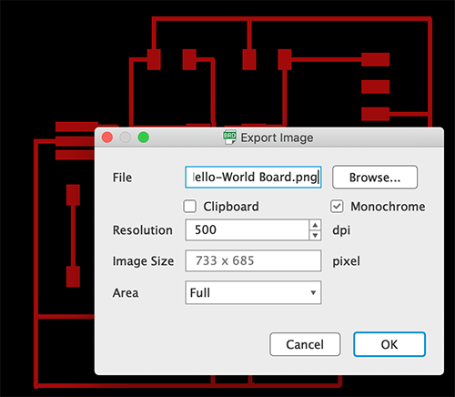
Export the document as a png image, with 500 dpi and in 'Monochrome'.
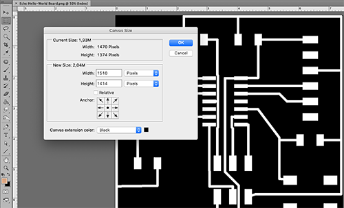
Add an extra margin of 20px around in Photoshop to prevent from problems while milling.
7.2.3. PCB milling
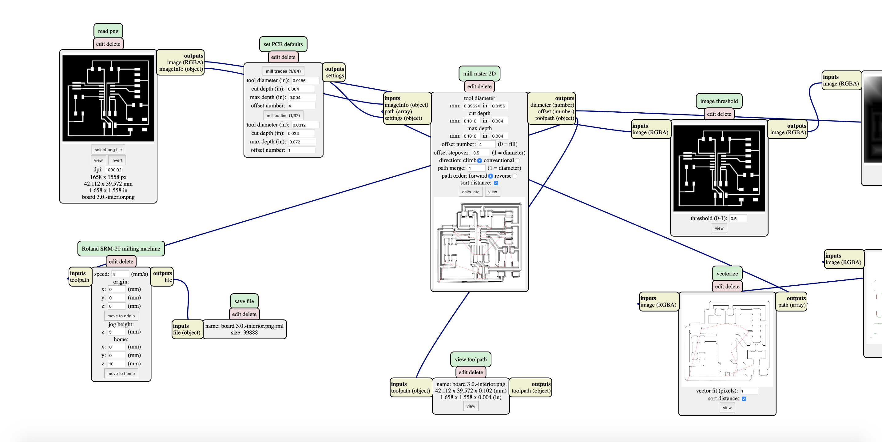
Once we got the final png files, we can set the milling parameters on the mods website to get the .rml files (for inner milling and outer cut), as done in Electronics Production assignment.
First we open the png file on mods server and define the inner milling, and outter cut; and create the .rml files for milling:
We proceed to follow the same steps for milling the board:
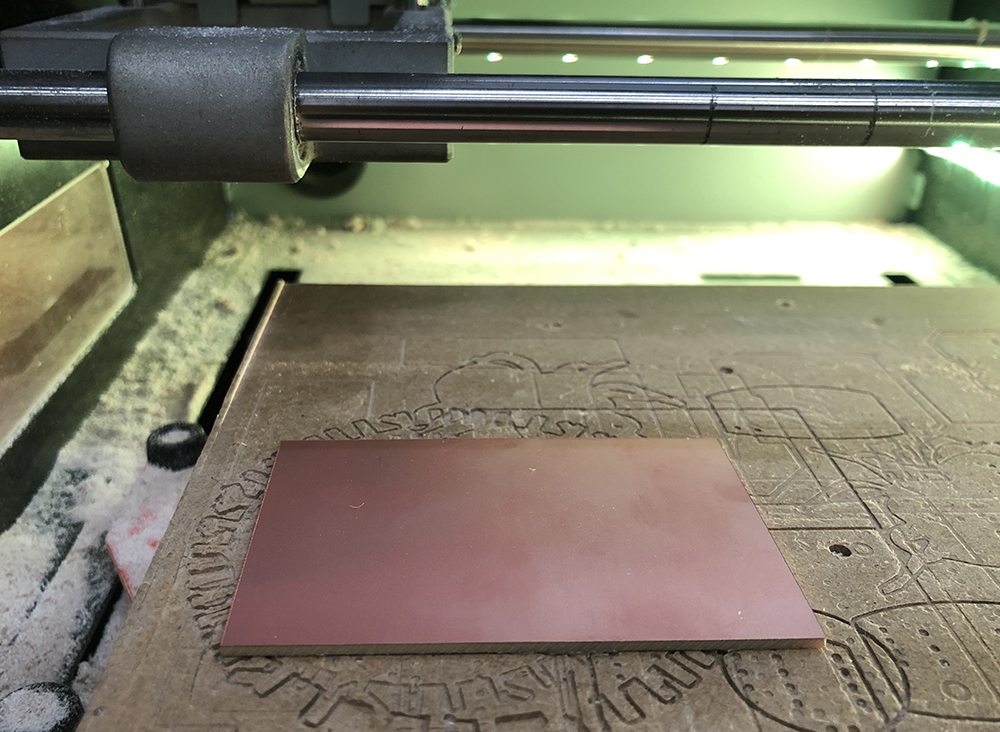
First, set the board on top of the milling bed
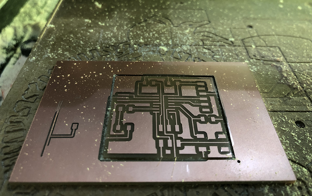
Then, I got problems with the outer cut due to the definition of the path line:
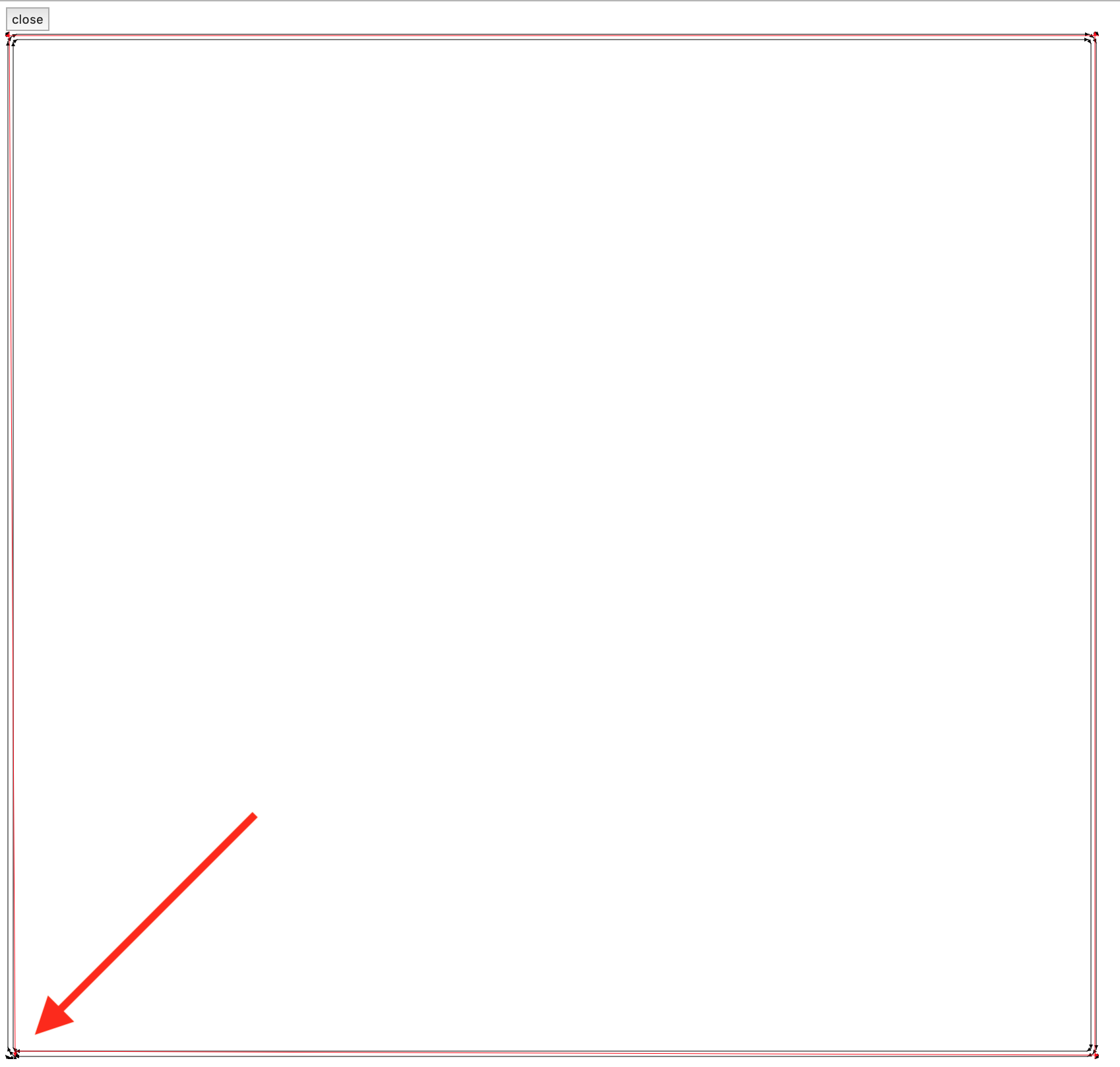
I need to invert the drawing in mods to get the proper config on the .rml file.
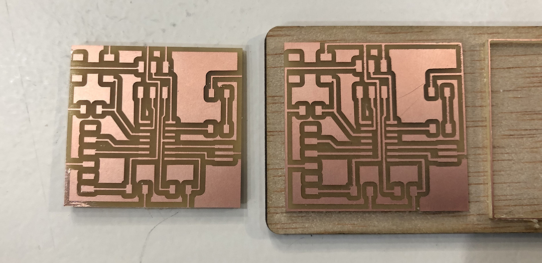
After finishing, this is the result of my final milled board (down) compared with the faulty one (up).
7.3.4. PCB soldering
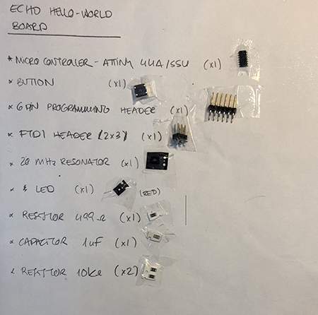
Set all components to be solded on a paper.
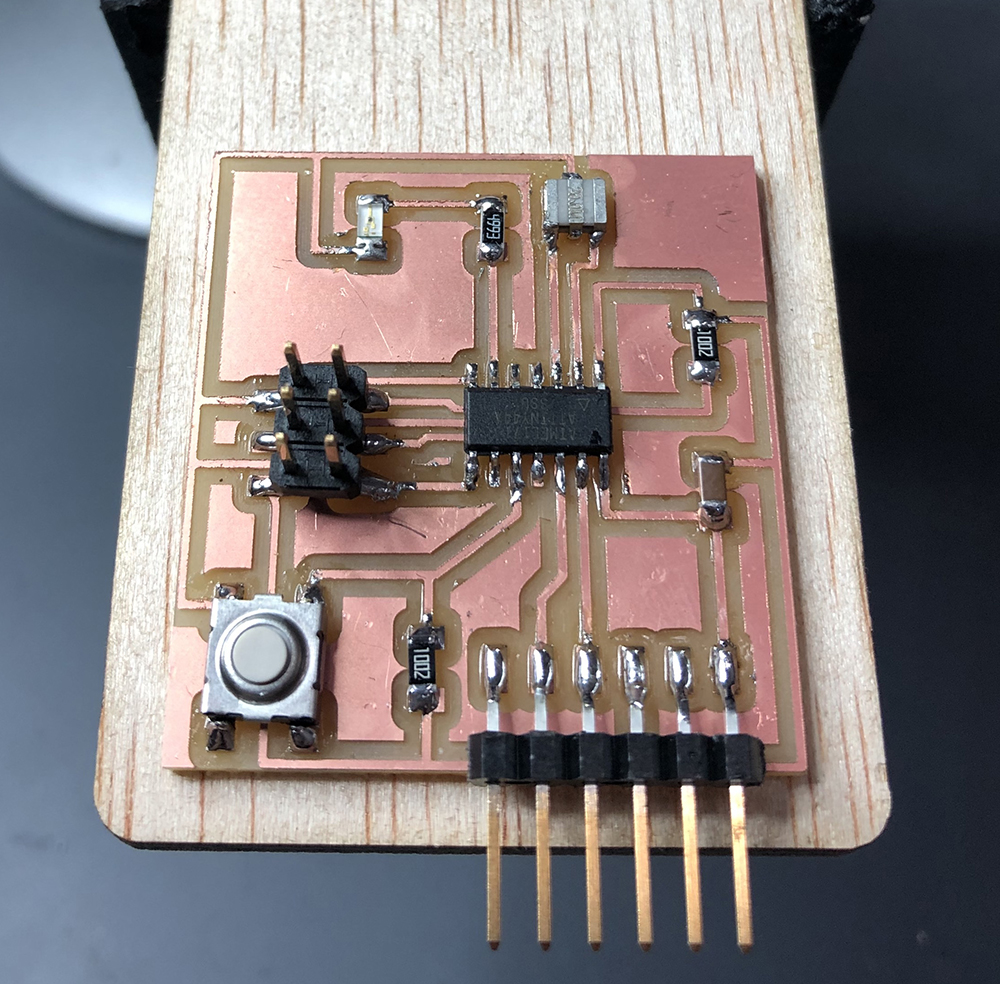
After soldering all the elements on the board, this is how it should look like. It's important to start soldering from the microcontroller, to the components in the middle and end with the ones on the edges.
Also bare in mind the orientation of LEDs and polarized capacitors, and also leave enough space for FTDI's black plastic connections so that can touch the board instead of hanging from the edge.
7.2.5. PCB testing
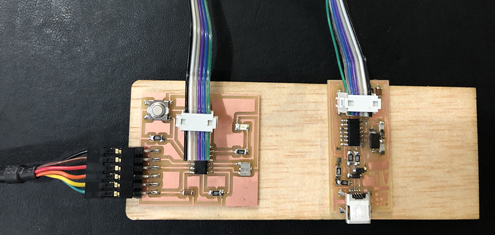
The first thing to do is testing all the connections with a multimeter to check there are no shortcuts and everything is connected correctly. Check first if the GND cable on the FTDI is connected to the correct pin, and also the socket-jumper cable header to the ISP connectors.