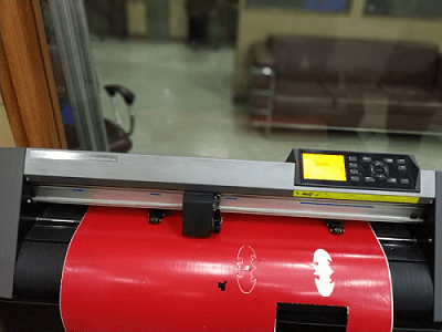
Computer controlled cutting


So the task for this week was to learn and implement computer cutting tools, softwares and techniques.
The goal is to get hands dirty on experience with the machines like laser cutter and vinyl plotter and learn about the capabilities of the machine as well as the intricacies of it.
My goal for this week was to hands on vinyl plotter as well as laser cutter. For laser cutting it was required to make a parametric 2D model identifying the process involved in producing it.
Another group assignment was to identify the kerf of the machine so as to construct the design accorfingly to make a better press fit.
For vinyl plotter it was required to get hands on and produce some sort of stickers.

Vinyl Plotter


Graphtec-CE-6000
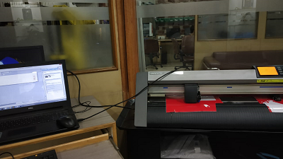
Starting off with the vinyl plotter. Th software used is Graphtec Studio Provided by our instrutor. First you load the material you want to cut, in my case it was vinyl sheet. There are two rollers b/w which the sheet is fed. Make sure the upper roller meets the lower roller where the surface is rough so that they can hold the vinyl better. 
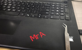
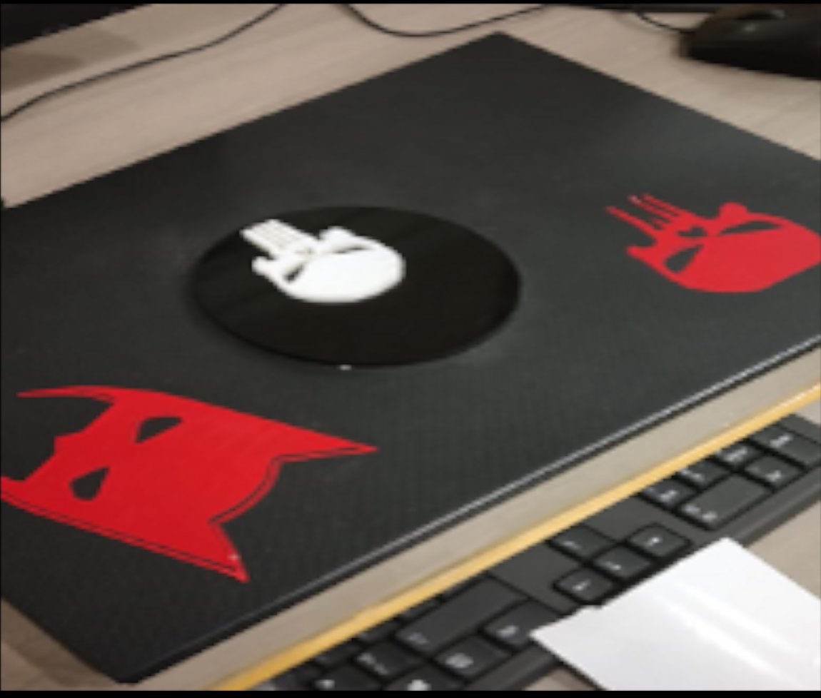
In the lab there were red colored vinyl sheets available so the task was to design something and cut the stencils and characterize the machine. 
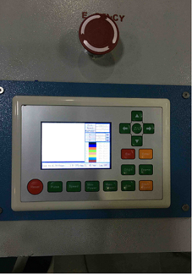
Now before operating any tool there are some safety measures that you need to take care of.


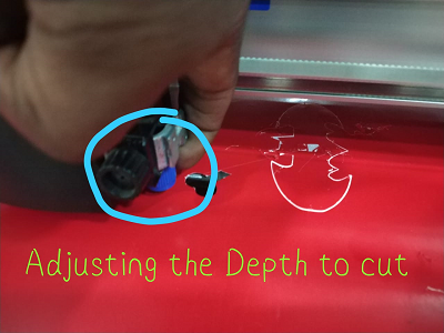
This is the adjustment of tooltip by which you can adjust the depth of the cut that you want to have.


The Setup

Steps to be followed for cutting
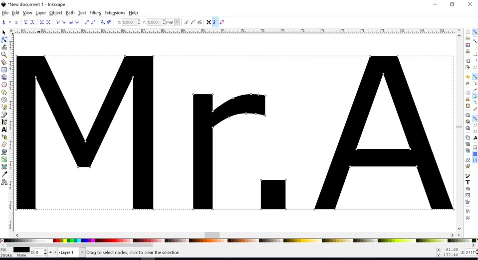
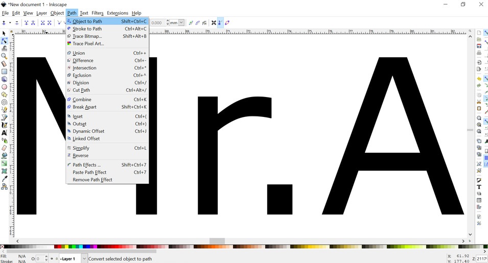
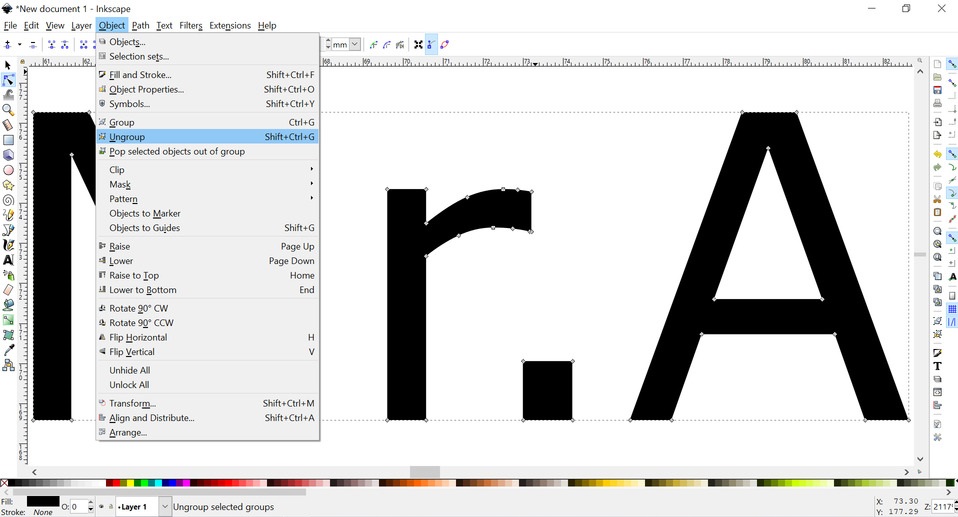
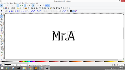
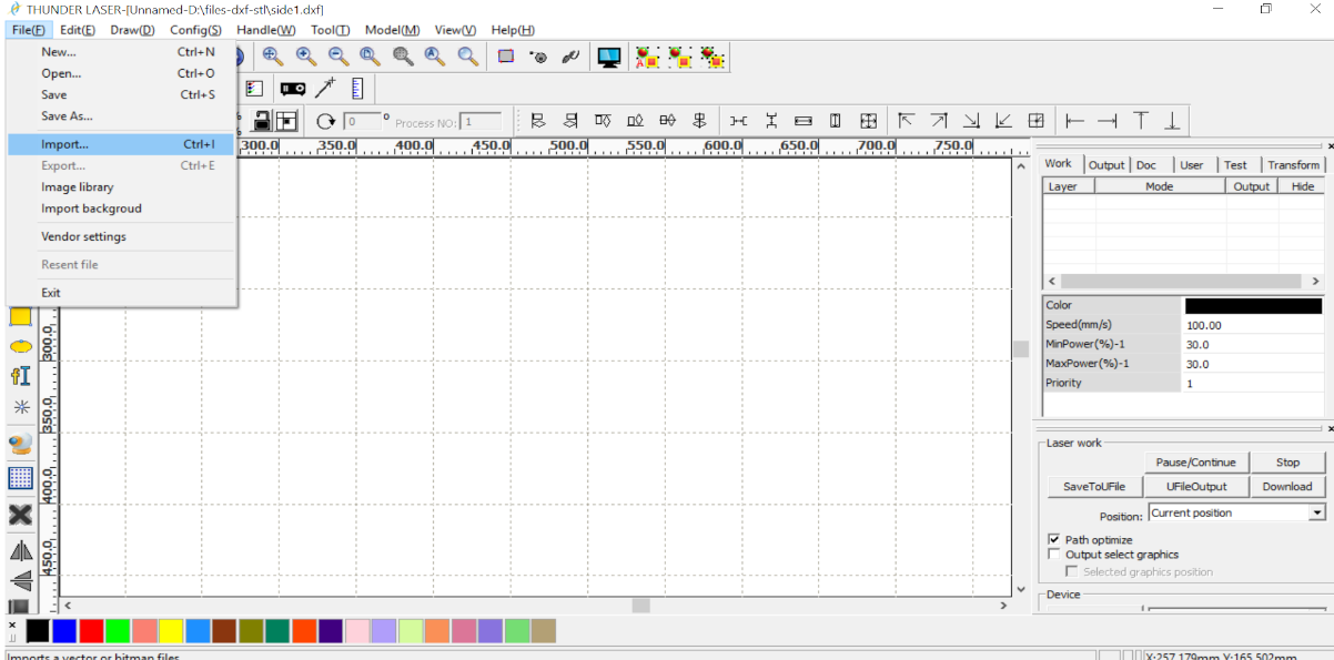
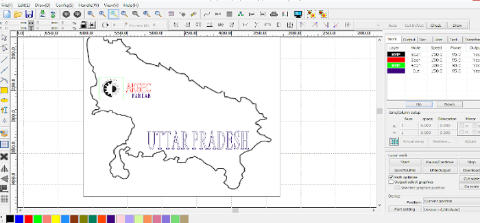
  1. Import the desired image in the software or you can make design using inkscape or any software available to you(any format would do,high resolution preferred).
  2. Adjust the size of the image by dragging the cursor.
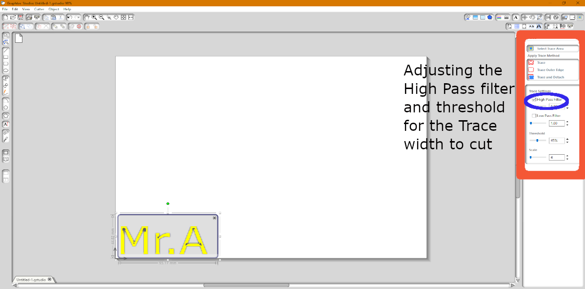
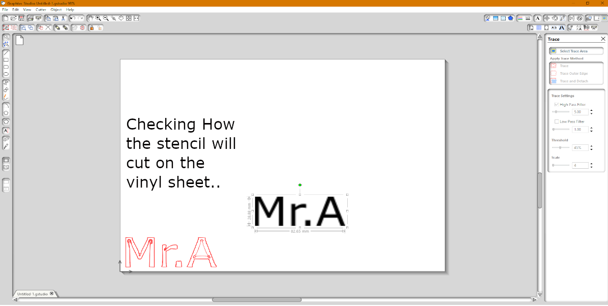
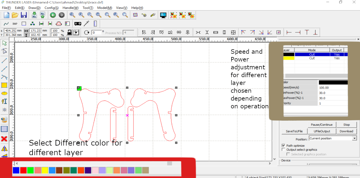
  3. Click the Trace Option from the upper right, here there are various options A.Trace Outer Edge B.Trace C.Trace and detach
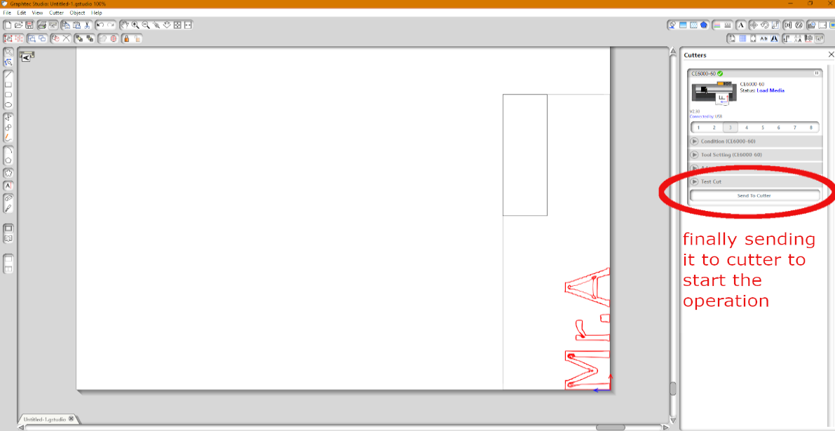
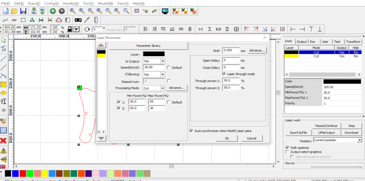
    You can adjust the trace settings by using the high pass/low pass filters as well as the threshold. I would suggest to play with them untill you get the desired form of stencils to cut.(I did the same)
  4. Set the origin by pressing the origin buuton on the machine by dragging it to the desired area.
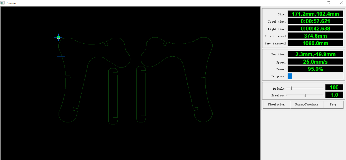
  5. Connect the plotter and click SEND TO CUTTER(if the status on the right tool bar should show you its ready if it's not connected it will show you not connected).
  6. The machine should the cut the required files , after that take the masking tape and peel of the sticker with the help of the masking tape. A knife would irksome at times.

Making My name in Inkscape and vectorised it to Cut it On the Vinyl Plotter-


Connecting to the Vinyl plotter using GRAPHTEC Studio Software to Select the traces that I want to cut out

And then Send to cutter

Weeding

The transfer tape was unavailable at lab so the most creative task was weeding out the vinyl from the sheet,
Weeding vinyl is the process of removing the unwanted vinyl from your cut design. You can think of it like weeding a garden: you carefully dig up all the little pieces that aren't supposed to be there, without destroying any of your beautiful flowers.
I used a very pointy tweezer to remove the parts then Pasted them carefully on my Laptop.

Then I downloaded some Images from google to test the cut, After every search I write Decals on google coz it gives best result realted to vinyl cut image. I searchedf for Batman Decals and Punisher Decals and downloaded it, Imported it to the graphtec studio and taced out the elements I wanted and Send to the cutter.

Batman
Image for punisher sticker -source google

Also I tried to make someflexible PCB's using Vinyl in week 5 go to that week through this link.


Laser Cutter(The most Overrated Machine in almost all The FAB LABs)

For the laser cutting assignment I thought it to be comparatively easy as I have been introduced to it since a year working on it for my college projects and for the ROBOCON project. But I was amazed to see that what I knew earlier was just a lil part of the whole game. I never used to take account the intricacies and the capabilities of the machines. This was mainly cleared during the Group assignment that we all were given collectively.
The assignment was to characterize the machine and run several tests before initiating the actual work.
The laser cutter we are having in our lab is a Chinese one which is mostly used in India supplied by SIL

The Group Assignment

The first and foremost was to identify the safety measures and follow the norms coz lasers can be dangerous.
The next step was to characterize our machine- basically the Two main operations can be done via laser

  • Cutting
  • Engraving/Scanning

For this we need to know the most important parameteres that are
  • Speed, and
  • Power
At Fab Lab AKGEC we have CO2 Laser that is favourable for materials like ply wood/mdf/acrylic sheets. Our task was to carry out the test of speed and power on the materials and find out optimum speed for cutting and engraving for the material which is being used.
The goal for this test was to prevent the material wastage as well as finding the right tuning for the machine.
For this we made a speed card for the cutting test on 2mm cardboard and a shade card for scanning test on the acrylic sheet. The design files were prepared by Ashish who took the big lead for this week in making the design files.

Operating the laser cutter

The software we used for laser cutting is RDWorks.
On the machine there is a panel that shows various rows to move the pointer for setting the origin. After achieving the desired origin press --> enter on the panel. It has a bit of it's own memory which u can save files and can directly cut via browsing them or else you can operate it via software. A chiller is kept on the other side which is the temperature controller of the laser it cools it down. We were advised not to work if the temperature indication was above 26.


The Speed/Power Card

Shade Card


The outcome was that the optimum power and speed for cutting of a 2mm card board is 30/30 respectively.


Comparison of Materials on the Speed And Power


Material: Cardboard 2mm
Power(Cut) 30-40 %
Speed 30 mm/sec
Material: MDF
Power(Cut) 75-90 %
Speed 20-25 mm/sec
Material: Acrylic
Power(Cut) 60-80%
Speed 40-50mm/sec
Material: Ply wood
Power(Cut) 90-95%
Speed 10-12 mm/sec

Accounting for the kerf-


Kerf is basically the material that gets lost during the process of operation.
Basically some of material which get lost during the process is of very minute order depending upon the machine but to have a better understanding for making a press fit the know how of kerf was important fo a good design rule.

-Images were clicked by a fellow student.

I was initially so bewildered by this word but it was needed for a better pressfit assignmment and then Ashish made me clear about it that whenever a laser works on a material especially when it cuts, it ablates out some material by burning it, so basically kerf is that extra material of which we have to consider in making our designs. We made a square of 1inch by 1 inch and when we measure the width not actually 1inch= 25.4mm it was 19.47mm

So now we condsider the left over part is kerf = 5.93 which was eually divided to both the sides so = 5.93/2 = 2.96 for 10 blocks so 2.96/10 = .296 mm ~.30 mm
The Learning through kerf was to understand for making a good design that the measurement is exactly what we want we need to add the amount that is ablated or removed or rather taking 'kerf' into account.


Download All test files from here


PressFit Kit

It was the individual assignment, after having a hard thought like everyone else was trying some living hinges and complicated press fits I wanted to solve a personal problem I needed a stand at my organizer to keep my things, so i decided to make a it.I used Fusion 360 for parametric designing and exported is as dxf file for laser cutting.
You can download the fusion file from here Stand.f3d

Assigning parameters-
    The parameters I gave to my design-

  • MatThickness

  • TabDepth

  • StandWidth

The I extruded the stand

Then I selected the rectangle tool and made ade arectangle on the edes and gave it the dimension as my parameters.


Changing the width parameter showing results-


Importing DXF in RD Works

First I exported the file in dxf format from fusion 360 by clicking in the part I want the edit as sketch and save as DXF.

The I opened RD works And Imported the Dxf Files


Now the bottom Colored PAnel is to select various layers to adjust the speed and power of the Laser.
It's used when we try to raster or different shades suppose in a wood etching a photo different layers will raster them according to their respective adjusted speed and power.

Here I used MDF so refer to the Test Table above this page we found out during testing and used the same results.
Download The dxf files from here
You can see the Simulation by clicking the Simulation Tab on the top of the task bar

However It just tells how the laser will follow the path nie xact info about speed and power can be deric=ved from It It can be done By testing through the materials.

The laser in action-

The Outcome was really satisfying-

Making parts for the assignment (Multiple Assembly)-


The Outcome-

Slide for Images

Some Extra Fun

My Lab Manager told me to make a map of our city do that it could be installed in th Lab, So I downloaded the image in o=png format of our city and Vectorised it using inkscape and the imported in the RDWorks to give the operation on Laser.

Using Slicer for Fusion 360


Slicer is free plugin for Fusion 360. you just have to import the STL 3d file created in fusion 360 and chose the object size
Then after Just select the pattern in which you want to xut and select in a way that there are no red lines
Red line indicates thats not pressfit you can create various patterned geometry using this Plugin.


Fun with laser Cutter


Issues faced

As being the oldest member of the lab and knowing that the the machine has gone into pahse where it was not very well maintained due which we informed our Manager and he has asked the support service to fix the issues. For working continously for a bit of time the chiller starts showing the increase in temperature annd laser pulse stops coming initially we thought it was just because of the chiller so we changed the water of the chiller(needs to be replaced by evey 15th day) But then too after sometime the pulse agin stopped coming after that the next day somehow the pulse worked fine but while doing some task Along with Ashish the tooltip was stuck at Y axis and his file was messed up the necessary actions have already been taken it will be serviced by the end of the week.

Chiller Temperature before working
Final Chiller temperature after changing it's water


Learning Outcome

Top